IXLAPRBHIInductive Reader
Deister Electronic GmbH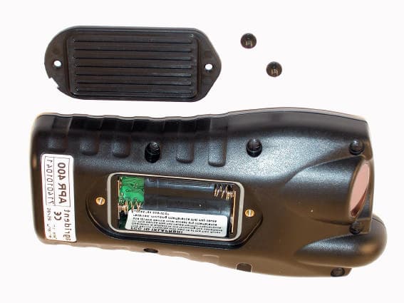
Click to zoom
Application Details
- Equipment Class
- DXX - Part 15 Low Power Communication Device Transmitter
- Date of Grant
- Jun 12, 2005
- Application Purpose
- Original Equipment
- Date of Application
- Jun 12, 2005
- Equipment Note
- Inductive Reader
- Frequency Range
- 0.13420000 - 0.13420000
- Company
- Deister Electronic GmbH
- Country
- Germany
Documents & Files
Document Text
Text extracted from the exhibit documents filed with the FCC. Open a document above to read the original.
Users Manual
HANDHELD BHT, BHT lite, BHI, BHI Pro Manual - Draft - V07/06/05 2deister electronic GmbH 30890 Barsinghausen Germany V07/06/05 BiTech Handheld Manual -DRAFT - © Copyright 2005 by deister electronic GmbH All rights reserved. No part of this publication may be reproduced, stored in a retrieval system, or transmitted, in any form or by any means, electronic, mechanical, photocopying, recording or otherwise, without prior written permission of Agrident GmbH. Agrident GmbH reserves the right to make changes to any and all parts of this documentation without obligation to notify any person or entity of such changes. June 2005 SE/BB deister electronic GmbH Hermann-Bahlsen-Str. 11 30890 Barsinghausen Germany Telefon: +49 (0) 51 05 - 51 61 11 Telefax: +49 (0) 51 05 - 51 62 17 E-Mail: [email protected] Web:www.deister.com V07/06/05deister electronic GmbH 30890 Barsinghausen Germany 3 BiTech Handheld Manual-DRAFT- Contents 1Introduction ..................................................................... 5 1.1The 8 keys for the operation....................................................................................... 6 1.2The status messages in the second line of the DISPLAY ................................................. 6 1.3The acoustic signals .................................................................................................. 6 2Operating the BiTech reader .......................................... 7 2.1Power on.................................................................................................................. 7 2.2Start READ................................................................................................................ 7 2.3Quick start ............................................................................................................... 7 2.4No ID found ............................................................................................................. 8 3DISPLAY and SAVE of an ID............................................. 9 3.1Standard mode without ACTION CODE ..................................................................... 9 3.2Modus with ACTION CODE ASK ............................................................................... 9 3.3Modus with ACTION CODE AUTO ............................................................................ 9 3.4Modus with an alphanumeric FORMAT of the ACTION CODE ..................................... 9 3.5Modus with ACTION CODE PLUS function ................................................................. 9 3.6Modus DISPLAY ...................................................................................................... 10 4The SETUP of the BiTech reader .................................... 10 4.1Operation within the menu ...................................................................................... 10 4.2The OPERATION menu ........................................................................................... 10 4.2.1LAST ID.................................................................................................................. 11 4.2.2HOTKEY A and HOTKEY B ...................................................................................... 11 4.3The SETUP menu .................................................................................................... 12 4.3.1RF/ID menu............................................................................................................ 12 4.3.2BAUDRATE............................................................................................................. 12 4.3.3DISPLAY ................................................................................................................. 12 4.3.4DISPLAY FORMAT................................................................................................... 13 4.3.5TIME and DATE ...................................................................................................... 14 4.3.6VOLUME of Acoustic Signals.................................................................................... 14 4.3.7POWER MANAGER ................................................................................................ 14 4.3.8SOFTWARE VERSION ............................................................................................. 14 4.3.9DEFAULT ............................................................................................................... 14 4.4The DATA MENU.................................................................................................... 14 4.4.1MEMORY SPACE .................................................................................................... 15 4.4.2SHOW DATA ......................................................................................................... 15 4.4.3SHOW TAG LIST .................................................................................................... 15 4.4.4USR TAG LIST......................................................................................................... 15 4.4.5DATA SEND ........................................................................................................... 15 4.4.6LINK LIST SEND ...................................................................................................... 15 5The DEFAULT setting...................................................... 16 6Technical Data ............................................................... 17 4deister electronic GmbH 30890 Barsinghausen Germany V07/06/05 BiTech Handheld Manual -DRAFT - V07/06/05deister electronic GmbH 30890 Barsinghausen Germany 5 BiTech Handheld Manual-DRAFT- 1 Introduction The portable full-ISO BiTech readers are so small - they fit even into a shirt pocket - they have a very handy design and are easy to operate even under worse conditions. The readers are compatible to the ISO standard 11785 and read FDX-B and HDX. Tags with the widely used chip type H4102…
Text truncated - open the document above for the full version.
Users Manual
Agrident GmbH, Hermann Bahlsen Str. 11-13, D-30890 Barsinghausen Phone +49 5105 520614 - Fax +49 5105 520616 APR Handheld Reader Operation Manual DRAFT V07/06/05 APR300/400 07.06.05 Vertraulich / Confidential Page 2 of 19 © Copyright 2005 by Agrident GmbH All rights reserved. No part of this publication may be reproduced, stored in a retrieval system, or transmitted, in any form or by any means, electronic, mechanical, photocopying, recording or otherwise, without prior written permission of Agrident GmbH. Agrident GmbH reserves the right to make changes to any and all parts of this documentation without obligation to notify any person or entity of such changes. June 2005 Agrident GmbH Hermann-Bahlsen-Str. 11-13 30890 Barsinghausen Germany Phone +49 (0) 51 05 520614 Fax +49 (0) 51 05 520616 E-Mail: [email protected] www.agrident.com APR300/400 07.06.05 Vertraulich / Confidential Page 3 of 19 Contents 1. Introduction ......................................................................................................... 5 2. BASIC operation of APR readers............................................................................ 6 2.1 The 8 keys for the operation ..................................................................... 6 2.2 The status messages in the second line of the DISPLAY ......................... 6 2.3 The acoustic signals.................................................................................. 6 3. Operating the APR.............................................................................................. 7 3.1 Power on................................................................................................... 7 3.2 Start READ ............................................................................................... 7 3.3 Quick start................................................................................................. 7 3.4 No ID found ............................................................................................... 7 4. DISPLAY and SAVE of an ID.............................................................................. 8 4.1 Standard mode without ACTION CODE ................................................... 8 4.2 Modus with ACTION CODE ASK .............................................................. 8 4.3 Modus with ACTION CODE AUTO ........................................................... 8 4.4 Modus with an alphanumeric FORMAT of the ACTION CODE................. 8 4.5 Modus with ACTION CODE PLUS function .............................................. 8 4.6 Modus DISPLAY ANIMAL ID .................................................................... 9 5. The SETUP of the APR ...................................................................................... 9 5.1 Operation within the menu ........................................................................ 9 5.2 The OPERATION menu............................................................................ 9 5.2.1 LAST ID .......................................................................................... 9 5.2.2 HOTKEY A and HOTKEY B.......................................................... 10 5.3 The SETUP menu ................................................................................... 10 5.3.1 RF/ID menu................................................................................... 10 5.3.2 BAUDRATE .................................................................................. 11 5.3.3 ONLINE MODE ............................................................................. 11 5.3.4 DISPLAY ....................................................................................... 11 5.3.5 DISPLAY FORMAT....................................................................... 12 5.3.6 TIME and DATE............................................................................ 13 5.3.7 VOLUME of Acoustic Signals........................................................ 13 5.3.8 POWER MANAGER ..................................................................... 13 5.3.9 SOFTWARE VERSION................................................................. 13 5.3.10 DEFAULT...................................................................................... 13 APR300/400 07.06.05 Vertraulich / Confidential Page 4 of 19 5.4 The DATA MENU.................................................................................... 13 5.4.1 MEMORY SPACE......................................................................... 13 5.4.2 SHOW DATA ................................................................................ 14 5.4.3 SHOW TAG LIST .......................................................................... 14 5.4.4 USR TAG LIST.............................................................................. 14 5.4.5 CLEAR DATA ............................................................................... 14 5.4.6 CLEAR MEMORY ......................................................................... 14 5.4.7 MEMORY FULL............................................................................ 14 5.4.8 CLEAR LIST ................................................................................. 14 5.4.9 DATA SEND ................................................................................. 14 5.4.10 LINK LIST SEND........................................................................... 15 6. The DEFAULT setting....................................................................................... 15 7. Technical Data .................................................................................................. 16 8. Safety and care................................................................................................. 17 9. Regulatory notices............................................................................................ 18 APR300/400 07.06.05 Vertraulich / Confidential Page 5 of 19 1. Introduction The portable full-I…
Text truncated - open the document above for the full version.
Cover Letter(s)
deister electronic GmbH - Hermann-Bahlsen-Straße 11-13 D-30890 Barsinghausen ! IDENTIFIKATION PHOENIX TEST-LAB GmbH! SICHERHEITSTECHNIK Product Certification! VERKEHRSELEKTRONIK Königswinkel 10 ! 05105-516-01 32825 Blomberg " 05105-516217 19.05.2005 RE:Certification Application FCC ID:IXLAPRBHI Pursuant to Sections 0.459 of the Commission's Rule, deister electronic GmbH, hereby requests confidential treatment of information accompanying this application as outlined below: - schematic diagrams - block diagram - technical description of operation The application contains technical information which deister electronic GmbH deems to be trade secrets and proprietary. If made public, the information might be used to the disadvantage of the applicant in the market place. Thank you for your attention in this matter. (Stefan Eichler) deister electroinc GmbHHandelsregister :Bankverbindungen :Kto.-Nr.BLZ Hermann-Bahlsen-Straße 11-13Amtsger. Wennigsen HBR 1203Stadtsparkasse Barsinghausen05 304(251 512 70) 30890 BarsinghausenGeschäftsführung:Dresdner Bank Hannover76 142 02(250 800 20) ! (+49) 05105 516 01Anatoli StobbeDeutsche Bank Barsinghausen4 686 424(250 700 70) " (+49) 05105 516 217USt-IdNr. : DE 115507822Postgiro Hannover612 23-303 (250 100 30) Mitglied . BHE ®
Internal Photos
Annex B of test report R50476_A Edition 1 EUT: APR400 / BiTech BHI Manufacturer: deister electronic GmbH Examiner: Thomas KÜHNDate of issue: 26 April 2005page 1 of 3 50476_6.jpgAPR400 / BiTech BHI PCB, top view Annex B of test report R50476_A Edition 1 EUT: APR400 / BiTech BHI Manufacturer: deister electronic GmbH Examiner: Thomas KÜHNDate of issue: 26 April 2005page 2 of 3 50476_5.jpgAPR400 / BiTech BHI PCB, bottom view Annex B of test report R50476_A Edition 1 EUT: APR400 / BiTech BHI Manufacturer: deister electronic GmbH Examiner: Thomas KÜHNDate of issue: 26 April 2005page 3 of 3 50476_7.jpgAPR400 / BiTech BHI detail view PCB and display
Test Report
Königswinkel 10 32825 Blomberg Germany Phone+49 5235 9500-0 Fax+49 5235 9500-10 TEST REPORT Test Report Reference: R50476_A Edition 1 Equipment under Test: APR400 / BiTech BHI Serial Number: 7140101001 Applicant: deister electronic GmbH Manufacturer: deister electronic GmbH Test Laboratory (CAB) accredited by DATech e.V. in compliance with DIN EN ISO/IEC 17025 under the Reg. No. DAT-P-105/99-21 and listed by FCC 31040/SIT1300F2 TEST REPORT REFERENCE: R50476_A Edition 1 Examiner: Thomas KÜHNDate of issue: 26 April 2005Page 2 of 23 Contents:Page 1 IDENTIFICATION.....................................................................................................................................3 1.1 APPLICANT.....................................................................................................................................3 1.2 MANUFACTURER..........................................................................................................................3 1.3 DATES.............................................................................................................................................3 1.4 TEST LABORATORY......................................................................................................................4 1.5 RESERVATION...............................................................................................................................4 1.6 NORMATIVE REFERENCES..........................................................................................................4 1.7 TEST RESULTS..............................................................................................................................4 2 TECHNICAL DATA OF EQUIPMENT......................................................................................................5 2.1 DEVICE UNDER TEST...................................................................................................................5 2.2 PEREPHERY DEVICES..................................................................................................................5 2.3 SPECIAL EMC MEASURES...........................................................................................................5 3 OPERATIONAL STATES AND PHYSICAL BOUNDARIES.....................................................................6 4 LIST OF TEST MODULES.......................................................................................................................7 4.1 EMISSION.......................................................................................................................................7 5 METHOD OF MEASUREMENT...............................................................................................................8 5.1 RADIATED EMISSIONS 9 kHz to 30 MHz......................................................................................8 5.2 RADIATED EMISSIONS 30 MHz to 1 GHz.....................................................................................10 6 TEST RESULTS EMISSION TEST..........................................................................................................13 6.1 PRELIMINARY RADIATED EMISSION TEST (9 kHz to 30 MHz)..................................................13 6.2 PRELIMINARY RADIATED EMISSION TEST (30 MHz to 1 GHz).................................................15 6.3 FINAL RADIATED EMISSION TEST (9 kHz to 30 MHz)................................................................17 6.4 OCCUPIED BANDWIDTH...............................................................................................................18 7 TEST EQUIPMENT AND ANCILLARIES USED FOR TESTS.................................................................19 8 LIST OF ANNEXES..................................................................................................................................23 TEST REPORT REFERENCE: R50476_A Edition 1 Examiner: Thomas KÜHNDate of issue: 26 April 2005Page 3 of 23 1IDENTIFICATION 1.1APPLICANT Name:deister electronic GmbH Address:Hermann-Bahlsen-Straße 11 – 13 30890 Barsinghausen Country:Germany Name for contact purposes:Mr. Stefan Eichler Tel:+49 51 05 516-129 Fax:+49 51 05 516-266 e-mail address:[email protected] 1.2MANUFACTURER Name:deister electronic GmbH Address:Hermann-Bahlsen-Straße 11 – 13 30890 Barsinghausen Country:Germany Name for contact purposes:Mr. Stefan Eichler Tel:+49 51 05 516-129 Fax:+49 51 05 516-266 e-mail address:[email protected] 1.3DATES Date of receipt of test sample:21 February 2005 Start of test:08 March 2005 End of test:08 March 2005 TEST REPORT REFERENCE: R50476_A Edition 1 Examiner: Thomas KÜHNDate of issue: 26 April 2005Page 4 of 23 1.4TEST LABORATORY The tests were carried out at:PHOENIX TESTLAB GmbH Königswinkel 10 D-32825 BlombergPhone: +49 (0) 52 35 / 95 00-0 GermanyFax:+49 (0) 52 35 / 95 00-10 accredited by DATech e.V. in compliance with DIN EN ISO/IEC 17025 under Reg. No. DAT-P-105/99-21 and listed by FCC 31040/SIT1300F2. Test engineer:Thomas KÜHN26 April 2005 NameSignatureDate Test report checked:Bernd STEINER26 April 2005 NameSignatureDate Stamp 1.5RESERVATION T h i s t e s t r e p o r t i s o n l y v a l i d i n i t s o r i g i n a l f o r m. Any reproduction of its contents without written permission of the accredited test laboratory PHOENIX TESTLAB GmbH is prohibited. The test results herein refer only to the tested sample. PHOENIX TESTLAB GmbH is not responsible for any generalisations or conclusions drawn from these test results concerning further samples. Any modification of the tested samples is prohibited and leads to the invalidity of this test report. Each page necessarily contains the PHOENIX TESTLAB Logo and the TEST REPORT REFERENCE. 1.6NORMATIVE REFERENCES [1] ANSI C63.4-2003 American National Standard for Methods of Measuring of Radio-Noise Emissions from Low- Voltage Electrical and Electronic Equipment in the Range of 9 kHz to 40 GHz. [2] FCC 47 CFR…
Text truncated - open the document above for the full version.
Test Setup Photos
Annex A of test report R50476_A Edition 1 EUT: APR400 / BiTech BHI Manufacturer: deister electronic GmbH Examiner: Thomas KÜHNDate of issue: 26 April 2005page 1 of 3 50476_f.jpgAPR400 / BiTech BHI, test set-up shielded chamber Annex A of test report R50476_A Edition 1 EUT: APR400 / BiTech BHI Manufacturer: deister electronic GmbH Examiner: Thomas KÜHNDate of issue: 26 April 2005page 2 of 3 50476_g.jpgAPR400 / BiTech BHI, test set-up fully anechoic chamber Annex A of test report R50476_A Edition 1 EUT: APR400 / BiTech BHI Manufacturer: deister electronic GmbH Examiner: Thomas KÜHNDate of issue: 26 April 2005page 3 of 3 50476_d.jpgAPR400 / BiTech BHI, test set-up outdoor test site
Contact Information
Applicant
Nicolas Stobbe(Head of Business Development)
Test Firm
Phoenix TestLab GmbHH. Altmaier
Technical Specifications
| # | Rule Parts | Frequency Range | Power Output |
|---|---|---|---|
| 1 | 15C | 0.1342 MHz - 0.1342 MHz | - |
Other Applications from Deister Electronic GmbH
IXLPRT6KPT6
Oct 07, 2024RFID Reader
Equipment Class
DXX - Part 15 Low Power Communication Device Transmitter
IXLSWH6000PCB
Oct 07, 2024RFID Reader
Equipment Class
DXX - Part 15 Low Power Communication Device TransmitterIXLPRDI4IC
Nov 01, 2021Access Control Reader Module
Equipment Class
DCD - Part 15 Low Power Transmitter Below 1705 kHz
IXLRHX
Aug 05, 2020Door Lock LF Read Head
Equipment Class
DXT - Part 15 Low Power Transceiver, Rx Verified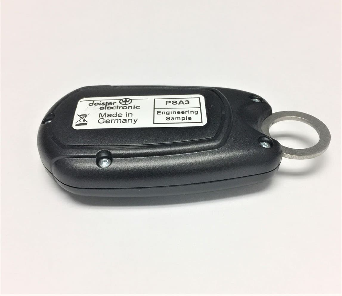
IXLPSA3
Apr 26, 2020Personal Tag Transponder
Equipment Class
DXT - Part 15 Low Power Transceiver, Rx Verified