IXLMBL1Bluetooth Credential Reader Module
Deister Electronic GmbH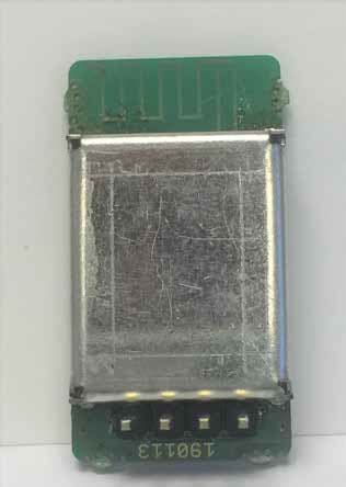
Click to zoom
Application Details
- Equipment Class
- DXT - Part 15 Low Power Transceiver, Rx Verified
- Date of Grant
- Feb 12, 2020
- Application Purpose
- Original Equipment
- Date of Application
- Feb 05, 2020
- Equipment Note
- Bluetooth Credential Reader Module
- Frequency Range
- 2402.00000000 - 2480.00000000
- Company
- Deister Electronic GmbH
- Country
- Germany
Documents & Files
Document Text
Text extracted from the exhibit documents filed with the FCC. Open a document above to read the original.
Users Manual
3. Technical Data Dimensions: mm (inch) 29 x 15.5 x 11.5 (1.14 x 0.61 x 0.45) Operating temperature: °C (°F) +5 ... +60 (+41 ... +140) Interface: RX/TX (3.3V TTL) Power supply: 5 V/DC (3.3 to 5.5 V) <20 mA Operating frequency: 2.4 GHz Electrical connection: 4-PIN plug connector 3. Technische Daten Abmaße: mm 29 x 15,5 x 11,5 Betriebstemperatur: °C +5...+60 Schnittstellen: RX/TX (3,3 V TTL) Spannungsversorgung: 5 V/DC (3.3 to 5.5 V) <20 mA Arbeitsfrequenz: 2.4 GHz Elektr. Anschluss: 4-poliger Steckverbinder 3. Données Techniques Dimensions: mm 29 x 15,5 x 11,5 Temp. de fonctionnement: °C +5...+60 Interface: RX/TX (3,3 V TTL) Alimentation: 5 V/DC (3.3 to 5.5 V) <20 mA Fréquence de fonctionnement: 2.4 GHz Connexions electriques: Connecteur enfichable à 4 broches Modular approval FCC ID: IXLMBL1 In accordance with FCC part 15.249, the MBL1 is listed as a modular transmitter device. Conformément à la section 15.249 des règlements FCC, le module MBL1 est répertorié comme un dispositif émetteur modulaire. This module is evaluated for stand-alone use only. Finished products incorporating multiple transmitters must comply with colocation and RF exposure requirements in accordance with FCC multi- transmitter product procedures. Collocated transmitters operating in portable RF Exposure conditions (e.g. <20 cm from persons including but not limited to body worn and hand held devices) may require separate approval. Ce module n'est évalué que pour une utilisation autonome. Les produits finis incorporant plusieurs émetteurs doivent être conformes à la colocation et aux exigences d'exposition RF en concordance avec les procédures FCC multi- metteurs. D'autres émetteurs fonctionnant dans des dispositifs portables exposés aux RF (par exemple, situés à moins de 20 cm des personnes avec dispositifs portatifs ou portés contre le corps) peuvent nécessiter d'une approbation séparée. 5.1 Test Modes Required for Host Product Evaluation Testing of the host product with all the transmitters installed is recommended, to verify that the host product meets all the applicable FCC rules. The radio spectrum is to be investigated with all the transmitters in the final host product functioning to determine that no emissions exceed the highest limit permitted for any one individual transmitter as required by Section 2.947(f). A formal application for certification submission containing the results of this investigation is not required. The host manufacturer is responsible to ensure that when their product operates as intended it does not have any emissions present that are out of compliance that were not present when the transmitters were tested individually.5 The following provides general guidance and suggestions to host product manufacturers when installing a certified modular transmitter, on how they may verify the intentional radiator (transmitter) compliance of the composite-system end product. a) If the modular transmitter has been fully tested by the module grantee on the required number of channels, modulation types, and modes, it should not be necessary for the host installer to re-test all the available transmitter modes or settings. It is recommended that the host product manufacturer, installing the modular transmitter, perform some investigative measurements to confirm that the resulting composite system does not exceed the spurious emissions limits or band edge limits (e.g., where a different antenna may be causing additional emissions). b) The testing should check for emissions that may occur due to the intermixing of emissions with the other transmitters, digital circuitry, or due to physical properties of the host product (enclosure). This investigation is especially important when integrating multiple modular transmitters where the certification is based on testing each of them in a stand-alone configuration. It is important to note that host product manufacturers should not assume that because the modular transmitter is certified that they do not have any responsibility for final product compliance. c) If the investigation indicates a compliance concern the host product manufacturer is obligated to mitigate the issue. Host products using a modular transmitter are subject to all the applicable individual technical rules as well as to the general conditions of operation in Sections 15.5, 15.15, and 15.29 to not cause interference. The operator of the host product will be obligated to stop operating the device until the interference has been corrected. d) The following test modes should be followed by the manufacturer to ensure that the module, when incorporated, meets all emissions requirements. (1) Obtain from the manufacturer the following special test firmware along with firmware loading tool: a. L68x_BLE_Modul b. L67x_BLE_Modul_CW_Low_Channel c. L69x_BLE_Modul_CW_Mid_Channel d. L70x_BLE_Modul_CW_High_Channel (2) Firmware a. above is production firmware of the module as delivered. Load each of the other three firmwares in turn and test your system for normal and regulatory performance. The return production firmware to the module. e) When incorporating this module the manufacturer should consider the following worst cases incorporation scenarios: (1) Ensure that the power supplied to the module is no greater than 5.5VDC. 5.5 VDC is a worst case and should not be exceeded. (2) Ensure that the power supply ripple is no greater than 0.1V RMS. 0.1V RMS is a worst case and should not be exceeded. (3) Ensure that the module is a minimum of 6 mm from any ground plane. Performance cannot be assured if a ground plane is closer than 6 mm to the module. (4) Ensure that the module is a minimum of 20 mm from any other intentional radiator. Performance cannot be assured if another intentional radiator is closer than 20 mm from the module. Il est recommandé de tester le produit hôte avec tous les émetteurs installés afin de vérifier que le produit hôte respecte toutes les règles FCC applicables. Le spectre radioélect…
Text truncated - open the document above for the full version.
Cover Letter(s)
Deister Electronics USA, Inc. 9817 Godwin Drive #201 Manassas, VA 20110 Direct Line: +1-703-659-9497 Direct FAX: +1-415-762-1963 Email: [email protected] www.deister.com 30 April 2019 To Whom It May Concern: We hereby delegate CKC Certification Services, LLC (CKC CS) power of attorney to act on our behalf in matters pertaining to certification of products. The actions of CKC CS shall be considered the same as our own. Sincerely, William L Nuffer President Deister Electronics USA, Inc. 9817 Godwin Drive #201 Manassas, VA 20110 1.703.368.2739
Cover Letter(s)
Deister Electronics USA, Inc. 9817 Godwin Drive #201 Manassas, VA 20110 Direct Line: +1-703-659-9497 Direct FAX: +1-415-762-1963 Email: [email protected] www.deister.com 4 June 2019 Federal Communications Commission 7435 Oakland Mills Road Columbia, MD 21046 Subject: Request for Permanent Confidentiality To whom it may concern: In accordance with 47CFR Section 0.457 and Section 0.459 pertaining to confidential material, we hereby request to hold permanently confidential all information contained within the below identified exhibits/document categories submitted pursuant to radio equipment certification requirements for FCC ID: IXLMBL1 1. Block Diagram 2. Operational Description 3. Schematics 4. Parts List The above material contains trade secrets and proprietary information as specified by 47CFR 0.457(d) and technical data, which would customarily be guarded from competitors. The public disclosure of this information might be harmful to our company and provide unjustified benefits to our competitors. Sincerely, William L Nuffer President Deister Electronics USA, Inc. 9817 Godwin Drive #201 Manassas, VA 20110 1.703.368.2739
Cover Letter(s)
Deister Electronics USA, Inc. 8576 Wellington Road Manassas, VA 20109 Direct Line: +1-703-659-9497 Email: [email protected] www.deister-usa.com 4 September 2019 Federal Communications Commission Office of Engineering and Technology 7435 Oakland Mills Road Columbia, MD 21046 To Whom It May Concern: This letter is to request Single Modular Approval in accordance with under FCC Rule Part 15.212(a)(1) for certification request under FCC ID: IXLMBL1. This product is short range Bluetooth Low Energy (BLE) transceiver and can be used in devices requiring communication with other BLE devices exchanging status and permission communications with said device into which it is incorporated. Declaration of conditions. Y/N 15.212(a)(1) Condition Y (i) The radio elements of the module have their own shielding. The physical crystal and tuning capacitors may be located external to the shielded radio elements Y (ii) The module has buffered modulation/data inputs (if such inputs are provided) to ensure that the module will comply with part 15 requirements under conditions of excessive data rates or over- modulation. Y (iii) The module has its own power supply regulation. Y (iv) The module complies with the antenna and transmission system requirements of §§15.203, 15.204(b) and 15.204(c). The antenna(s) are either permanently attached or employ a “unique” antenna coupler (at all connections between the module and the antenna, including the cable). Y (v) The module was tested in a stand-alone configuration, i.e., the module was not inside another device during testing for compliance with part 15 requirements. Unless the transmitter module will be battery powered, it complies with the AC line conducted requirements found in §15.207. AC or DC power lines and data input/output lines connected to the module do not contain ferrites, unless they will be marketed with the module (see §15.27(a)). The length of these lines was the length typical of actual use or, if that length is unknown, at least 10 centimeters was used to insure that there is no coupling between the case of the module and supporting equipment. Any accessories, peripherals, or support equipment connected to the module during testing were unmodified and commercially available (see §15.31(i)). Y (vi) The module is equipped with either a permanently affixed label or is capable of electronically displaying its FCC identification number. Y (vii) The module complies with any specific rules or operating requirements that ordinarily apply to a complete transmitter and the applicant has provided adequate instructions along with the module to explain any such requirements. Y (viii) The module complies with any applicable RF exposure requirements in its final configuration. The instructions provided with the module adequately explain any usage conditions or restrictions. I acknowledge on behalf of the applicant that compliance of this module in all final configurations is the responsibility of the applicant under the condition that the integrator follows all provided installation instructions. Sincerely, DEISTER ELECTRONICS USA, INC Bill Nuffer President
External Photos
F2P21510 Page 1 of 2 June 17, 2019 PHOTOGRAPHS: EXTERNAL Deister Electronics USA, Inc. - Model MBL1 Order Number: XXX Client: XXX Model: XXX F2P21510 Page 2 of 2 June 17, 2019
Internal Photos
F2P21510 Page 1 of 8 June 17, 2019 PHOTOGRAPHS: INTERNAL Deister Electronics USA, Inc. - Model MBL1 Order Number: F2P21510 Client: Deister Electronics USA, Inc. Model: MBL1 F2P21510 Page 2 of 8 June 17, 2019 Order Number: F2P21510 Client: Deister Electronics USA, Inc. Model: MBL1 F2P21510 Page 3 of 8 June 17, 2019 Order Number: F2P21510 Client: Deister Electronics USA, Inc. Model: MBL1 F2P21510 Page 4 of 8 June 17, 2019 Order Number: F2P21510 Client: Deister Electronics USA, Inc. Model: MBL1 F2P21510 Page 5 of 8 June 17, 2019 Order Number: F2P21510 Client: Deister Electronics USA, Inc. Model: MBL1 F2P21510 Page 6 of 8 June 17, 2019 Order Number: F2P21510 Client: Deister Electronics USA, Inc. Model: MBL1 F2P21510 Page 7 of 8 June 17, 2019 Order Number: F2P21510 Client: Deister Electronics USA, Inc. Model: MBL1 F2P21510 Page 8 of 8 June 17, 2019
Test Report
060818 Report Number: F2P21510-01E Page 1 of 37 Issue Date: Oct. 11, 2019 F2 Labs 16740 Peters Road Middlefield, Ohio 44062 United States of America www.f2labs.com CERTIFICATION TEST REPORT Manufacturer: Deister Electronic GMBH 11 Hermann Bahlsen Str Barsinghausen 30890 GERMANY Applicant: Deister Electronics USA, Inc. 9817 Godwin Drive, #201 Manassas, Virginia 20110 USA Product Name: Access Control Reader Bluetooth Adapter Product Description: BLE Module for optional connection to the Infinity Line of Access Control Readers to add Bluetooth Credentialing capability. Operating Voltage/Frequency: 2.7-5.5VDC Model: MBL1 FCC ID: IXLMBL1 Testing Commenced: June 7, 2019 Testing Ended: Oct. 11, 2019 Summary of Test Results: In Compliance The EUT complies with the EMC requirements when manufactured identically as the unit tested in this report, including any required modifications and/or manufacturer’s statement. Any changes to the design or build of this unit subsequent to this testing may deem it non-compliant. Standards: FCC Part 15 Subpart C, Section 15.249 FCC Part 15 Subpart C, Section 15.215(c) – Additional provisions to the general radiated emission limitations FCC Part 15 Subpart A, Section 15.31(e) – Measurement Standards FCC15.207 - Conducted Limits Order Number: F2P21510 Applicant: Deister Electronics USA, Inc. Model: MBL1 060818 Report Number: F2P21510-01E Page 2 of 37 Issue Date: Oct. 11, 2019 Evaluation Conducted by: Julius Chiller, EMC/Wireless Engineer Report Reviewed by: Ken Littell, Director of EMC & Wireless Operations F2 Labs F2 Labs F2 Labs 26501 Ridge Road 16740 Peters Road 8583 Zionsville Road Damascus, MD 20872 Middlefield, OH 44062 Indianapolis, IN 46268 Ph 301.253.4500 Ph 440.632.5541 Ph 317.610.0611 This test report may be reproduced in full; partial reproduction only may be made with the written consent of F2 Labs. The results in this report apply only to the equipment tested. Order Number: F2P21510 Applicant: Deister Electronics USA, Inc. Model: MBL1 060818 Report Number: F2P21510-01E Page 3 of 37 Issue Date: Oct. 11, 2019 TABLE OF CONTENTS Section Title Page 1 ADMINISTRATIVE INFORMATION 4 2 SUMMARY OF TEST RESULTS/MODIFICATIONS 7 3 TABLE OF MEASURED RESULTS 8 4 ENGINEERING STATEMENT 9 5 EUT INFORMATION AND DATA 10 6 LIST OF MEASUREMENT INSTRUMENTATION 11 7 OCCUPIED BANDWIDTH 12 8 FIELD STRENGTH OF EMISSIONS/RADIATED SPURIOUS 16 9 VARIATION OF THE INPUT POWER 26 10 CONDUCTED EMISSIONS 28 11 PHOTOGRAPHS 33 Order Number: F2P21510 Applicant: Deister Electronics USA, Inc. Model: MBL1 060818 Report Number: F2P21510-01E Page 4 of 37 Issue Date: Oct. 11, 2019 1 ADMINISTRATIVE INFORMATION 1.1 Measurement Location: F2 Labs in Middlefield, Ohio. Site description and attenuation data are on file with the FCC's Sampling and Measurement Branch at the FCC Laboratory in Columbia, MD. 1.2 Measurement Procedure: All measurements were performed according to the 2013 version of ANSI C63.10 and recommended FCC procedure of measurement of DXT operating under Section 15.249. A list of the measurement equipment can be found in Section 6. Order Number: F2P21510 Applicant: Deister Electronics USA, Inc. Model: MBL1 060818 Report Number: F2P21510-01E Page 5 of 37 Issue Date: Oct. 11, 2019 1.3 Uncertainty Budget: The uncertainty in EMC measurements arises from several factors which affect the results, some associated with environmental conditions in the measurement room, the test equipment being used, and the measurement techniques adopted. The measurement uncertainty budgets detailed below are calculated from the test and calibration data and are expressed with a 95% confidence factor using a coverage factor of k=2. The Uncertainty for a laboratory are referred to as Ulab. For Radiated and Conducted Emissions, the Expanded Uncertainty is compared to the Ucispr values to determine if a specific margin is required to deem compliance. Ulab Ucispr If Ulab is less than or equal to Ucispr, then: • compliance is deemed to occur if no measured disturbance exceeds the disturbance limit; • non-compliance is deemed to occur if any measured disturbance exceeds the disturbance limit. If Ulab is greater than Ucispr in table 1, then: • compliance is deemed to occur if no measured disturbance, increased by (Ulab – Ucispr), exceeds the disturbance limit; • non-compliance is deemed to occur if any measured disturbance, increased by (Ulab – Ucispr), exceeds the disturbance limit. Note: Only measurements listed in the tables above that relate to tests included in this Test Report are applicable. Measurement Range Combined Uncertainty Expanded Uncertainty Radiated Emissions <1 GHz @ 3m 2.54 5.07dB Radiated Emissions <1 GHz @ 10m 2.55 5.09dB Radiated Emissions 1 GHz to 2.7 GHz 1.81 3.62dB Radiated Emissions 2.7 GHz to 18 GHz 1.55 3.10dB AC Power Line Conducted Emissions, 150kHz to 30 MHz 1.38 2.76dB AC Power Line Conducted Emissions, 9kHz to 150kHz 1.66 3.32dB Measurement Range Expanded Uncertainty Radiated Emissions <1 GHz @ 3m 5.2dB Radiated Emissions <1 GHz @ 10m 5.2dB Radiated Emissions 1 GHz to 2.7 GHz Under Consideration Radiated Emissions 2.7 GHz to 18 GHz Under Consideration AC Power Line Conducted Emissions, 150kHz to 30 MHz 3.6dB AC Power Line Conducted Emissions, 9kHz to 150kHz 4.0dB Order Number: F2P21510 Applicant: Deister Electronics USA, Inc. Model: MBL1 060818 Report Number: F2P21510-01E Page 6 of 37 Issue Date: Oct. 11, 2019 1.4 Document History: Document Number Description Issue Date Approved By F2P21510-01E First Issue Oct. 11, 2019 K. Littell Order Number: F2P21510 Applicant: Deister Electronics USA, Inc. Model: MBL1 060818 Report Number: F2P21510-01E Page 7 of 37 Issue Date: Oct. 11, 2019 2 SUMMARY OF TEST RESULTS Test Name Standard(s) Results -20dB Occupied Bandwidth CFR 47 Part 15.215(c) Complies Field Strength of Emissions CFR 47 Part 15.249(a)(d) Complies Radiated Spurious Emissions CFR 47 Part 15.249(d) / Part 15.209 Complies Conducted Emissions CFR 47 Part 15.207(a) N/A Variation…
Text truncated - open the document above for the full version.
Test Setup Photos
F2P21510 Page 1 of 5 Oct. 11, 2019 PHOTOGRAPHS: TEST SETUP Deister Electronics USA, Inc. - Model MBL1 Field Strength of Emissions, Occupied Bandwidth Loop Antenna Order Number: F2P21510 Client: Deister Electronics USA, Inc. Model: MBL1 F2P21510 Page 2 of 5 Oct. 11, 2019 Radiated Spurious Emissions: 30 MHz to 1000 MHz Radiated Spurious Emissions: 1 GHz to 18 GHz Order Number: F2P21510 Client: Deister Electronics USA, Inc. Model: MBL1 F2P21510 Page 3 of 5 Oct. 11, 2019 Radiated Spurious Emissions: 18 GHz to 26 GHz Order Number: F2P21510 Client: Deister Electronics USA, Inc. Model: MBL1 F2P21510 Page 4 of 5 Oct. 11, 2019 Conducted Emissions Order Number: F2P21510 Client: Deister Electronics USA, Inc. Model: MBL1 F2P21510 Page 5 of 5 Oct. 11, 2019 Voltage Variations
Contact Information
Applicant
Nicolas Stobbe(Head of Business Development)
Non-Technical Contact
Deister Electronics USA, Inc.William Nuffer
[email protected]+1.703.368.2739
Test Firm
F2 LabsWendy Fuster
Technical Specifications
| # | Rule Parts | Frequency Range | Power Output |
|---|---|---|---|
| 1 | 15C | 2.40 GHz - 2.48 GHz | - |
Other Applications from Deister Electronic GmbH
IXLPRT6KPT6
Oct 07, 2024RFID Reader
Equipment Class
DXX - Part 15 Low Power Communication Device Transmitter
IXLSWH6000PCB
Oct 07, 2024RFID Reader
Equipment Class
DXX - Part 15 Low Power Communication Device TransmitterIXLPRDI4IC
Nov 01, 2021Access Control Reader Module
Equipment Class
DCD - Part 15 Low Power Transmitter Below 1705 kHz
IXLRHX
Aug 05, 2020Door Lock LF Read Head
Equipment Class
DXT - Part 15 Low Power Transceiver, Rx Verified
IXLPSA3
Apr 26, 2020Personal Tag Transponder
Equipment Class
DXT - Part 15 Low Power Transceiver, Rx Verified