IXLMODEL260Proximity Reader
Deister Electronic GmbH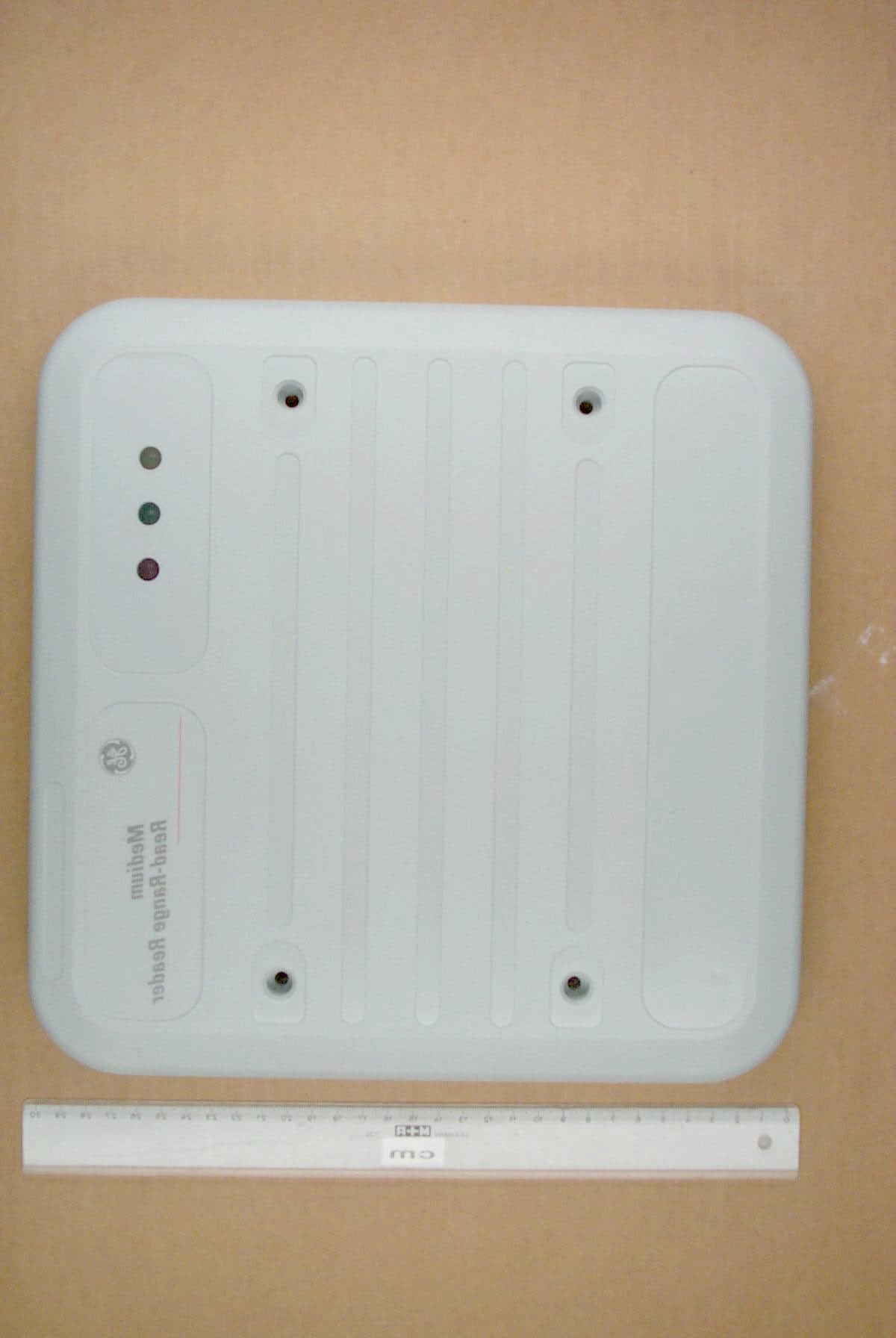
Click to zoom
Application Details
- Equipment Class
- DXX - Part 15 Low Power Communication Device Transmitter
- Date of Grant
- May 26, 2003
- Application Purpose
- Original Equipment
- Date of Application
- May 26, 2003
- Equipment Note
- Proximity Reader
- Frequency Range
- 13.56000000 - 13.56000000
- Company
- Deister Electronic GmbH
- Country
- Germany
Documents & Files
Document Text
Text extracted from the exhibit documents filed with the FCC. Open a document above to read the original.
Users Manual
GE Contactless Medium Read-Range Reader Model 260 Installation Guide 791 Park of Commerce Boulevard Suite 100 Boca Raton, Florida 33487 (561) 998-6100 Part Number: 460565001A February 2003 This document contains proprietary information of General Electric Company, USA and is furnished to it s customer solely to assist that customer in the installation, testing, operation, and/or maintenance of the equipment described. This document shall not be reproduced in whole or in part nor shall its contents be disclosed to any third party without the written approval of GE Industrial Systems.GE PROVIDES THE FOLLOWING DOCUMENT AND THE INFORMATION INCLUDED TH EREIN AS IS AND WITHOUT WARRANTY OF ANY KIND, EXPRESS OR IMPLIED, INCLUDING BUT NOT LIMITED TO ANY IMPLIED STATUTORY WARRANTY OF MERCHANTABILITY OR FITNESS FOR PARTICULAR PURPOSE.This publication may contain examples of screen captures and reports used in daily operations. Examples include fictitious names of individuals and companies. Any similarity to names and addresses of actual business enterprises and persons is entirely coincidental.Copyright 2003 GE Interlogix, CASIAll rights reserved.Printed in the U.S.AMIFARE ® is a registered trademark of Philips Electronics, N.V. WARNINGThis is a Class A product. In a domestic environment, this product may cause radio interference, in which case, the user may be required to take adequate measures. Model 260 Smart Card Reader i ContentsIntroduction ....................................................................................................... 1Product Overview ............................................................................................. 3 Features ................................................................................................. 3Access Control System Compatibility .............................................. 3 Mounting Considerations ................................................................................ 5 Environmental Interference ............................................................... 5Installation on Metal Surface ............................................................. 7 Installation........................................................................................................ 11 Installation: Model 260 on Metal ..................................................... 12Micro Selection ................................................................................... 13Reader-to-Micro Wiring Distance ................................................... 13Wiring.................................................................................................. 14Point-to-Point Wiring Diagrams...................................................... 16 Troubleshooting .............................................................................................. 23Technical Specifications ................................................................................. 26Regulatory Notices.......................................................................................... 28 ii GE Contactless Medium Read-Range Reader Model 260 FiguresFigure 1: GE Contactless Medium Read-Range Reader (Model 260) .................................................................... 1 Figure 2: GE Model 260 Reader Backplate (includes tamper switch) ................................................ 2 Figure 3: GE Model 260 Reader Environmental Considerations .. 5 Figure 4: Pole-Mounted Readers .................................................. 7 Figure 5: Parking Entrance/Exit Application A............................... 8 Figure 6: Parking Entrance/Exit Application B............................... 9 Figure 7: Parking Entrance Exit and Metal Sign Applications ..... 10 Figure 8: Model 260 Reader Backplate and Cover ..................... 11 Figure 9: GE Model 260 Reader Wiring Diagram to Micro/5 8RP 16 Figure 10: GE Model 260 Reader Wiring Diagram to J-Box ......... 17Figure 11: GE Model 260 Reader to 2RP ..................................... 18Figure 12: GE Model 260 to 8RP .................................................. 20Figure 13: GE Model 260 Reader to Micro/Reader Junction Box and Microcontroller 22 Figure 14: Stripping of Shield Grounds ......................................... 28 GE Contactless Medium Read-Range Reader Model 260 1 IntroductionThe GE Contactless Medium Read-Range Card (Model 260) is the latest evolution in contactless reader 13.56 MHz technology, and features universal compatibility with all ISO 15693 and ISO 14443A badge credentials. The GE Model 260 reader combines simple, cost-effective installation with the end-user convenience of extended read range. The reader housing is a durable gray polycarbonate making the reader equally well-suited for interior and exterior security locations. The reader is easy to install on all types of conventional and metal wall surfaces, stanchions, and pedestal-mount configurations . FIGURE 1: GE Contactless Medium Read-Range Reader (Model 260) 2 GE Contactless Medium Read-Range Reader Model 260 FIGURE 2: GE Model 260 Reader Backplate (includes tamper switch) GE Contactless Medium Read-Range Reader Model 260 3 Product OverviewFeatures• Exceptional read range of up to 14 inches (355.6 mm) for ISO 15693-compliant credentials. (Read range will vary with credential type and quality, as well as installation environment). • Universal compatibility with all ISO 15693 and ISO 14443A credentials (badges, disc tags, and key fobs). • Supervised four-state (open, closed, wire cut, and wire short) monitoring for door contacts and REX (request to exit) switches, and wiring. • Electrical protection (reverse polarity diode protection on power lines). • Data lines; high-speed transient voltage suppressor diodes • Compatible with Micro/5 2RP and 8RP Reader Processor boards, Micro/PX-2000, and Micro/PXN-2000 controllers • IP 65-rated sealed for deployment in both interior and exterior environments. • Integrated …
Text truncated - open the document above for the full version.
Cover Letter(s)
deister electronic GmbH - Hermann-Bahlsen-Straße 11-13 D-30890 Barsinghausen ! IDENTIFIKATION PHOENIX TEST-LAB GmbH! SICHERHEITSTECHNIK Product Certification! VERKEHRSELEKTRONIK Königswinkel 10 ! 05105-516-01 32825 Blomberg " 05105-516217 16. Mai 2003 RE:Certification Application FCC ID:IXLModel260 Please be advised that the following information is to be held confidential and behalf of deister electronic GmbH, Hermann-Bahlsen-Strasse 11-13, 30890 Barsinghausen, Germany: - circuit diagrams - schematic (component) diagrams - block diagram - technical description of operation The application contains technical information which deister electronic GmbH deems to be trade secrets and proprietary. If made public, the information might be used to the disadvantage of the applicant in the market place. Thank you for your attention in this matter. (Stefan Eichler) deister electroinc GmbHHandelsregister :Bankverbindungen :Kto.-Nr.BLZ Hermann-Bahlsen-Straße 11-13Amtsger. Wennigsen HBR 1203Stadtsparkasse Barsinghausen05 304(251 512 70) 30890 BarsinghausenGeschäftsführung:Dresdner Bank Hannover76 142 02(250 800 20) ! (+49) 05105 516 01Anatoli StobbeDeutsche Bank Barsinghausen4 686 424(250 700 70) " (+49) 05105 516 217USt-IdNr. : DE 115507822Postgiro Hannover612 23-303 (250 100 30) Mitglied . BHE ®
External Photos
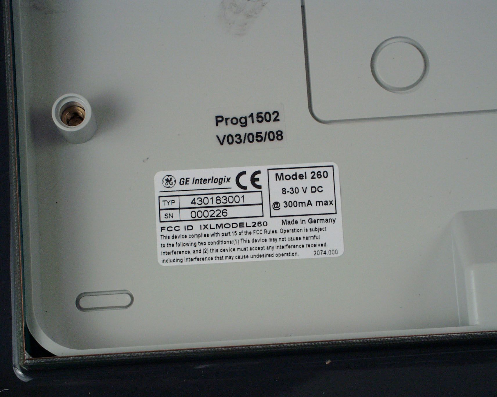
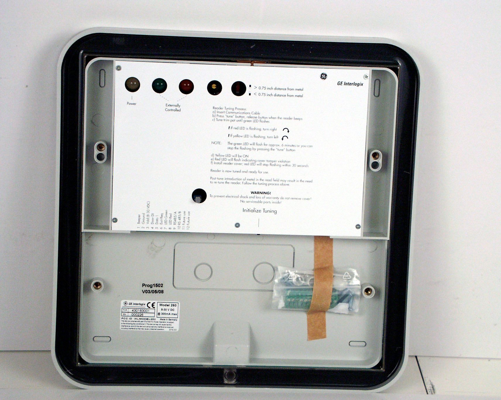
Annex B of test report R30052 Edition 2 EUT: Model 260 (PRA15) Manufacturer: deister electronic GmbH Examiner: Raimund BLASK Date of issue: 19 May 2003 page 1 of 2 30052eut1.jpg EUT, front view Annex B of test report R30052 Edition 2 EUT: Model 260 (PRA15) Manufacturer: deister electronic GmbH Examiner: Raimund BLASK Date of issue: 19 May 2003 page 2 of 2 30052eut2.jpg EUT, rear view
Internal Photos
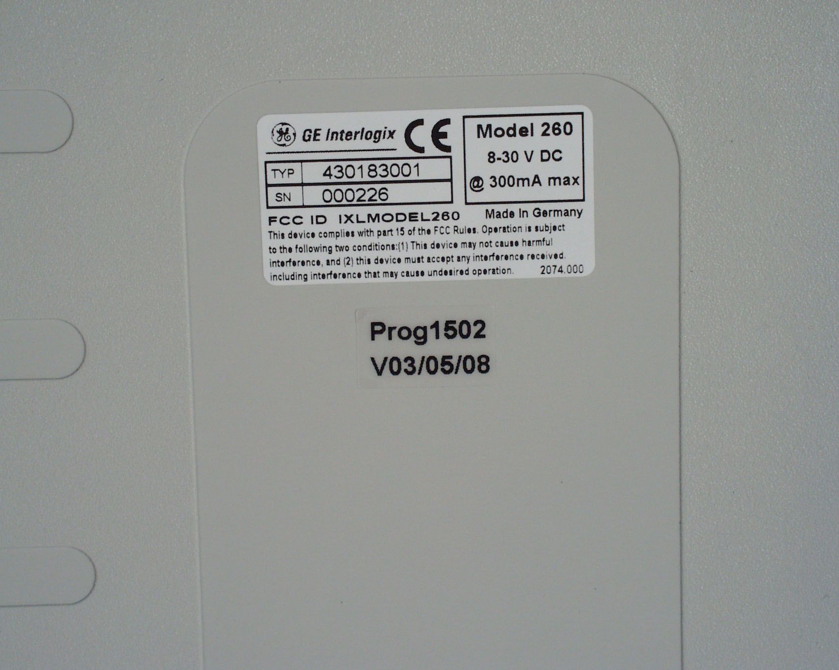
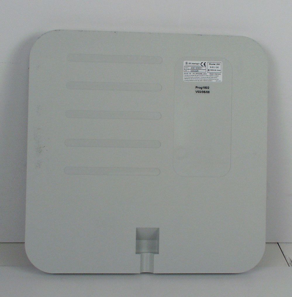
Annex C of test report R30052 Edition 2 EUT: Model 260 (PRA15) Manufacturer: deister electronic GmbH Examiner: Raimund BLASK Date of issue: 19 May 2003 page 1 of 2 30052eut3.jpg EUT, inside view Annex C of test report R30052 Edition 2 EUT: Model 260 (PRA15) Manufacturer: deister electronic GmbH Examiner: Raimund BLASK Date of issue: 19 May 2003 page 2 of 2 30052eut4.jpg EUT, PCB front view
Test Report
Königswinkel 10 32825 Blomberg Germany Phone +49 5235 9500-0 Fax +49 5235 9500-10 Test Report Reference: R30052 Edition 2 Equipment under Test: Model 260 (PRA15) Serial Number: 430183001 / 000001 Applicant: deister electronic GmbH Manufacturer: deister electronic GmbH FCC ID: IXLMODEL260 Test Laboratory (CAB) accredited by DATech e.V. in compliance with DIN EN ISO/IEC 17025 under the Reg. No. TTI-P-G071/94-11 and listed by FCC 31040/SIT1300F2 TEST REPORT REFERENCE: R30052 Edition 2 Examiner: Raimund BLASK Date of issue: 19 May 2003 Page 2 of 27 Contents: Page 1 IDENTIFICATION .................................................................................................................................... 3 1.1 APPLICANT .................................................................................................................................... 3 1.2 MANUFACTURER.......................................................................................................................... 3 1.3 DATES ............................................................................................................................................ 3 1.4 TEST LABORATORY ..................................................................................................................... 4 1.5 RESERVATION .............................................................................................................................. 4 1.6 NORMATIVE REFERENCES......................................................................................................... 4 1.7 TEST RESULTS ............................................................................................................................. 4 2 TECHNICAL DATA OF EQUIPMENT .....................................................................................................5 2.1 DEVICE UNDER TEST .................................................................................................................. 5 2.2 PEREPHERY DEVICES ................................................................................................................. 5 3 OPERATIONAL STATES AND PHYSICAL BOUNDARIES .................................................................... 6 4 LIST OF TEST MODULES ...................................................................................................................... 7 4.1 EMISSION ...................................................................................................................................... 7 METHOD OF MEASUREMENT ................................................................................................................. 8 4.2 RADIATED EMISSIONS 9 kHz to 30 MHz ..................................................................................... 8 4.3 RADIATED EMISSIONS 30 MHz to 1 GHz .................................................................................... 10 4.4 FREQUENCY STABILITY WITH RESPECT TO AMBIENT TEMPERATURE AND SUPPLY VOLTAGE....................................................................................................................................... 12 5 TEST RESULTS EMISSION TEST ......................................................................................................... 14 5.1 PRELIMINARY RADIATED EMISSION TEST (9 kHz to 30 MHz) ................................................. 14 5.2 PRELIMINARY RADIATED EMISSION TEST (30 MHz to 1 GHz) ................................................ 16 5.3 FINAL RADIATED EMISSION TEST (9 kHz to 30 MHz) ............................................................... 18 5.4 FINAL RADIATED EMISSION TEST (30 MHz to 1 GHz)............................................................... 19 5.5 OCCUPIED BANDWIDTH..............................................................................................................21 5.6 FREQUENCY TOLLERANCE ........................................................................................................ 22 6 TEST EQUIPMENT AND ANCILLARIES USED FOR TESTS ................................................................ 23 7 LIST OF ANNEXES ................................................................................................................................. 27 TEST REPORT REFERENCE: R30052 Edition 2 Examiner: Raimund BLASK Date of issue: 19 May 2003 Page 3 of 27 1 IDENTIFICATION 1.1 APPLICANT Name: deister electronic GmbH Address: Hermann-Bahlsen-Straße 11 – 13 30890 Barsinghausen Country: Germany Name for contact purposes: Mr. Stefan Eichler Phone: +49 51 05 516-129 Fax: +49 51 05 516-266 Mail address: [email protected] Applicant represented during the test by the following person: - 1.2 MANUFACTURER Name: deister electronic GmbH Address: Hermann-Bahlsen-Straße 11 – 13 30890 Barsinghausen Country: Germany Name for contact purposes: Mr. Stefan Eichler Phone: +49 51 05 516-129 Fax: +49 51 05 516-266 Mail address: [email protected] Manufacturer represented during the test by the following person: - 1.3 DATES Date of receipt of test sample: 2 May 2003 Start of test: 2 May 2003 End of test: 15 May 2003 TEST REPORT REFERENCE: R30052 Edition 2 Examiner: Raimund BLASK Date of issue: 19 May 2003 Page 4 of 27 1.4 TEST LABORATORY The tests were carried out at: PHOENIX TEST-LAB GmbH Königswinkel 10 D-32825 Blomberg Phone: +49 (0) 52 35 / 95 00-0 Germany Fax: +49 (0) 52 35 / 95 00-10 Test engineer: Raimund Blask 19 May 2003 name signature date Test report checked: Bernd Steiner 19 May 2003 name signature date stamp 1.5 RESERVATION This test report is only valid in its original form. Any reproduction of its contents without written permission of the accredited test laboratory PHOENIX TEST-LAB GmbH is prohibited. The test results herein refer only to the tested sample. PHOENIX TEST-LAB GmbH is not responsible for any generalisations or conclusions drawn from these test results concerning further samples. Any modification of the tested samples is proh…
Text truncated - open the document above for the full version.
Test Setup Photos
Annex A of test report R30052 Edition 2 EUT: Model 260 (PRA15) Manufacturer: deister electronic GmbH Examiner: Raimund BLASK Date of issue: 19 May 2003 page 1 of 5 30052emi5.jpg Test set-up preliminary emission measurement (9 kHz to 30 MHz) Annex A of test report R30052 Edition 2 EUT: Model 260 (PRA15) Manufacturer: deister electronic GmbH Examiner: Raimund BLASK Date of issue: 19 May 2003 page 2 of 5 30052emi1.jpg Test set-up preliminary emission measurement (30 MHz to 1 GHz) Annex A of test report R30052 Edition 2 EUT: Model 260 (PRA15) Manufacturer: deister electronic GmbH Examiner: Raimund BLASK Date of issue: 19 May 2003 page 3 of 5 30052emi_ff4.jpg Test set-up final emission measurement (9 kHz to 30 MHz) Annex A of test report R30052 Edition 2 EUT: Model 260 (PRA15) Manufacturer: deister electronic GmbH Examiner: Raimund BLASK Date of issue: 19 May 2003 page 4 of 5 30052ff2.jpg Test set-up final emission measurement (30 MHz to 1 GHz) Annex A of test report R30052 Edition 2 EUT: Model 260 (PRA15) Manufacturer: deister electronic GmbH Examiner: Raimund BLASK Date of issue: 19 May 2003 page 5 of 5 30052clima4.jpg Test set-up climatic chamber
Contact Information
Applicant
Nicolas Stobbe(Head of Business Development)
Technical Contact
deister electronic GmbHStefan Eichler
[email protected]+49 5105 516 01
Hermann-Bahlsen-Str. 11-13 · Barsinghausen · Germany
Non-Technical Contact
deister electronic GmbHStefan Eichler
[email protected]+49 5105 516 01
Test Firm
Phoenix TestLab GmbHH. Altmaier
Technical Specifications
| # | Rule Parts | Frequency Range | Power Output | Tolerance |
|---|---|---|---|---|
| 1 | 15C | 13.56 MHz - 13.56 MHz | - | 0.0100000000 % |
Other Applications from Deister Electronic GmbH
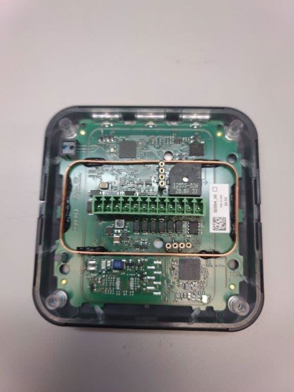
IXLPRT6KPT6
Oct 07, 2024RFID Reader
Equipment Class
DXX - Part 15 Low Power Communication Device Transmitter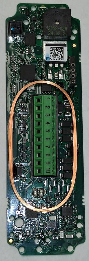
IXLSWH6000PCB
Oct 07, 2024RFID Reader
Equipment Class
DXX - Part 15 Low Power Communication Device TransmitterIXLPRDI4IC
Nov 01, 2021Access Control Reader Module
Equipment Class
DCD - Part 15 Low Power Transmitter Below 1705 kHz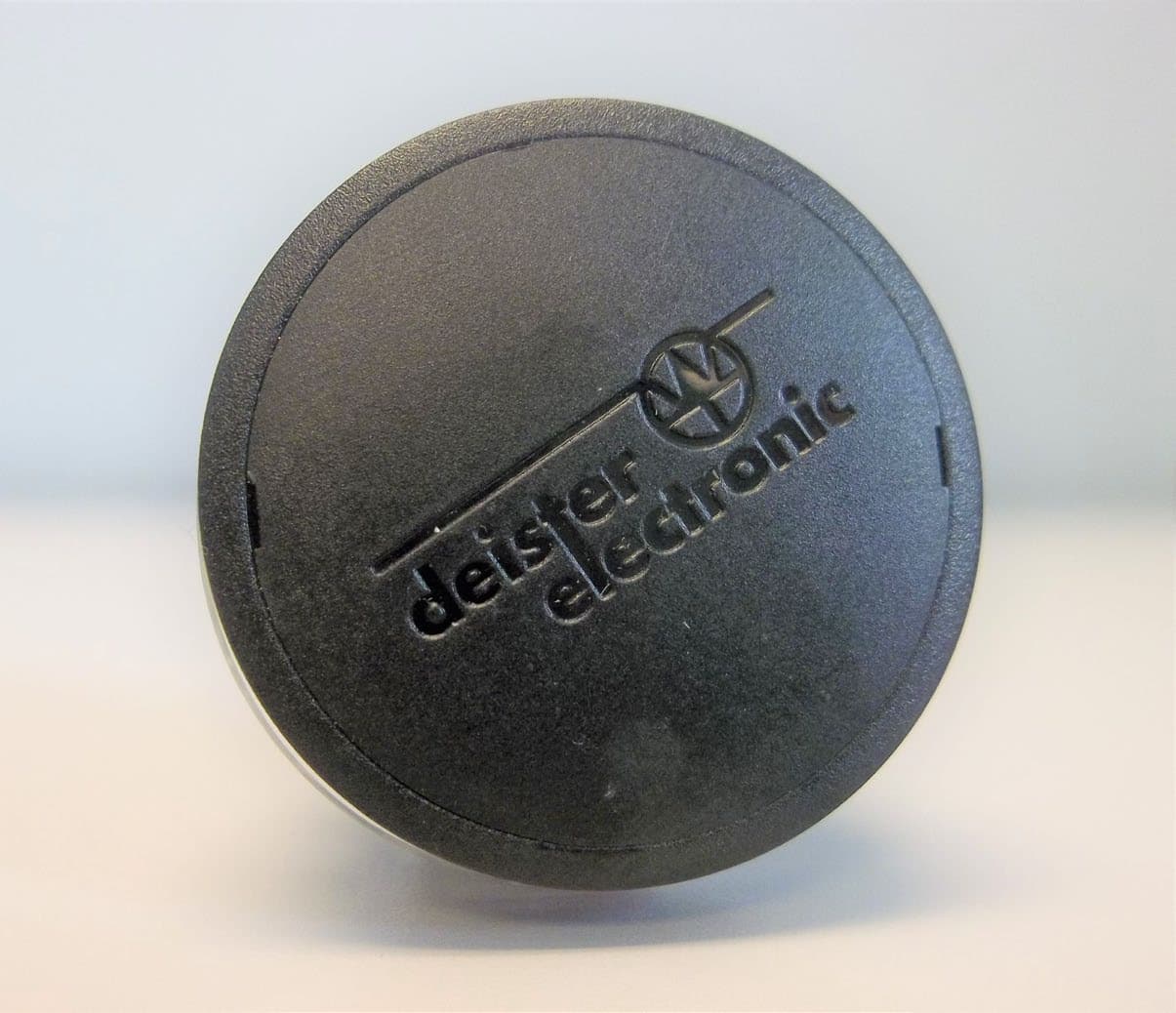
IXLRHX
Aug 05, 2020Door Lock LF Read Head
Equipment Class
DXT - Part 15 Low Power Transceiver, Rx Verified
IXLPSA3
Apr 26, 2020Personal Tag Transponder
Equipment Class
DXT - Part 15 Low Power Transceiver, Rx Verified