IXLPRM5MInductive Card Reader
Deister Electronic GmbH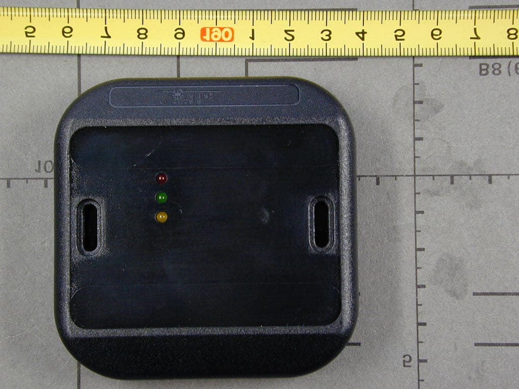
Click to zoom
Application Details
- Equipment Class
- DXX - Part 15 Low Power Communication Device Transmitter
- Date of Grant
- Jan 16, 2001
- Application Purpose
- Original Equipment
- Date of Application
- Jan 16, 2001
- Equipment Note
- Inductive Card Reader
- Frequency Range
- 13.55300000 - 13.56700000
- Company
- Deister Electronic GmbH
- Country
- Germany
Documents & Files
Document Text
Text extracted from the exhibit documents filed with the FCC. Open a document above to read the original.
Users Manual
03.01.01 © ‘2000 deister electronic GmbH Page 1/15 Wiring and Installation Instructions PRM 5 PRM 5 Wiring and Installation Instructions V 1.0 12/00 03.01.01 © ‘2000 deister electronic GmbH Page 2/15 Wiring and Installation Instructions PRM 5 FCC Compliance Statement This device complies with Part 15 of the FCC Rules. Operation is subject to the following two conditions: (1) this device may not cause harmful interference, and (2) this device must accept any interference received, including interference that may cause undesired operation. Information to user: Caution: Any changes or modifications not expressly approved by the party responsible for compliance could void the user's authority to operate the equipment © Copyright 2000 by deister electronic GmbH All rights reserved. No part of this publication may be reproduced, stored in a retrieval system, or transmitted, in any form or by any means, electronic, mechanical, photocopying, recording, or otherwise, without prior written permission of deister electronic GmbH. deister electronic GmbH reserves the right to make changes to any and all parts of this documentation without obligation to notify any person or entity of such changes. December 2000 deister electronic GmbH Hermann-Bahlsen-Str. 11 - 13 D-30890 Barsinghausen Phone: (+49) (0) (51 05) 5 16-01 Fax: (+49) (0) (51 05) 5 16-2 17 E-Mail: [email protected] 03.01.01 © ‘2000 deister electronic GmbH Page 3/15 Wiring and Installation Instructions PRM 5 Contents 1 Technical Data 2 Wiring Diagram 2.1 PRM 5 Wiegand 2-wire 2.2 PRM 5 Magstripe Emulation 2.3 PRM 5 RS 232 2.4 PRM 5 RS 485 2.5 Supervised F2F 3 Mechanical Dimensions 3.1 PRM 5 Reader 3.2 Surface Spacer AP5 3.3 Flush Mounting Bezel FM5 4 Communications Protocol 4.1 Wiegand Standard 4.2 Data/Clock 4.3 Magstripe Emulation 4.3.1 Magstripe Interface according to ISO 7811/2-1995 - Track 2 4.4 Protocol for PRM 5 with RS 232/RS 485 Interface (no Partyline protocol) 5 Installation 5.1 PRM 5 Reader 6 Interface 6.1 Indicators 6.2 Magstripe Emulation 6.3 Wiegand/Data/Clock 7 Appendix 7.1 Supervised F2F 03.01.01 © ‘2000 deister electronic GmbH Page 4/15 Wiring and Installation Instructions PRM 5 1 Technical Data Mounting: 1. Flush mounting in non-metallic surfaces 2. Surface mounting using an AP5 spacer 3. Mounting on single-gang electrical box using fixing plate FM 5 Material: ASA plastic housing; polyurethane encapsulated electronics Housing dimensions: 80 x 80 x 16 mm Temperature range: -25...+70 °C Power supply: 8...30 V DC <100 mA Electrical protection: Reverse polarity diode protection on power lines; high-speed transient voltage suppressor diodes on data lines Protection type: IP 65 (IEC 529) Frequency: 13.56 MHz Approvals: CE, EN 300 330 (European post) Reading distance: Up to 3 cm (depending on installation and transponder type) Data output mode: 1. One transmission per activity 2. Cyclical transmission Interface: 1. Wiegand 2-wire (open collector) 2. Data/Clock (open collector) 3. Magstripe emulation (open collector) 4. RS 232 5. RS 485 6. F2F Supervised Electrical connection: 12 position plug-in strip connector with screw terminals Beeper: External control Red LED: External control Green LED: External control Yellow LED: Indicates power to the reader 03.01.01 © ‘2000 deister electronic GmbH Page 5/15 Wiring and Installation Instructions PRM 5 2 Wiring Diagram Rear view of the reader 2.1 PRM 5 Wiegand 2-wire 2.2 PRM 5 Magstripe Emulation 03.01.01 © ‘2000 deister electronic GmbH Page 6/15 Wiring and Installation Instructions PRM 5 2.3 PRM 5 RS 232 RXD can be connected to Pin 5, but without any function. 2.4 PRM 5 RS 485 03.01.01 © ‘2000 deister electronic GmbH Page 7/15 Wiring and Installation Instructions PRM 5 2.5 Supervised F2F 03.01.01 © ‘2000 deister electronic GmbH Page 8/15 Wiring and Installation Instructions PRM 5 3 Mechanical Dimensions 3.1 PRM 5 Reader R 3030 11,50 7,50 12,50 2,50 69,50 80 52 80 R 5 R 2 0 2 6 ° 15,80 R 4 , 7 5 All dimensions in mm 3.2 Surface Spacer AP5 All dimensions in mm 03.01.01 © ‘2000 deister electronic GmbH Page 9/15 Wiring and Installation Instructions PRM 5 3.3 Flush Mounting Bezel FM5 All dimensions in mm 03.01.01 © ‘2000 deister electronic GmbH Page 10/15 Wiring and Installation Instructions PRM 5 4 Communications Protocol 4.1 Wiegand Standard 4.2 Data/Clock 4.3 Magstripe Emulation 03.01.01 © ‘2000 deister electronic GmbH Page 11/15 Wiring and Installation Instructions PRM 5 4.3.1 Magstripe Interface according to ISO 7811/2-1995 - Track 2 Data Encoding Table Value Bitpattern Meaning 0 0 0 0 0-1 “0” 1 1 0 0 0-0 “1” 2 0 1 0 0-0 “2” 3 1 1 0 0-1 “3” 4 0 0 1 0-0 “4” 5 1 0 1 0-1 “5” 6 0 1 1 0-1 “6” 7 1 1 1 0-0 “7” 8 0 0 0 1-0 “8” 9 1 0 0 1-1 “9” 10 (Ahex) 0 1 0 1-1 unused character 11 (Bhex) 1 1 0 1-0 start sentinel (start character) 12 (Chex) 0 0 1 1-1 unused character 13 (Dhex) 1 0 1 1-0 field separator 14 (Ehex) 0 1 1 1-0 unused character 15 (Fhex) 1 1 1 1-1 end sentinel (stop character) The least significant bit of every digit is sent first; the fifth bit is an odd parity bit for each group of 4 data bits. The complete message always looks as follows: left edge - start - data characters - end - LRC - right edge The LRC is calculated by the following procedure: Each of the 4 bits in the LRC character is an even parity bit of the equivalent bits in the telegram including start and stop sentinel; i. e. the first LRC bit is an even parity bit for all the least significant bits in the tele- gram and the 4th bit of the LRC is the even parity of all the most significant bits. The fifth bit is the odd parity of the 4 LRC bits (it is not calculated over all the parity bits). On magstripe cards the space left and right of the information (edge) is filled with an unknown number of zero bits (this is not a valid character as the parity is invalid). As most terminals need some of the zero bits (known as ‘‘clocking bits’’ too) and do not care about additional zero bits, deister decided to send 16 zero …
Text truncated - open the document above for the full version.
Cover Letter(s)
deister electronic GmbH - Hermann-Bahlsen-Straße 11-13 D-30890 Barsinghausen Letter Of Agency 12. Dezember 2000 American Telecommunications Certification Body, Inc. 6731 Whittier Avenue Suite C110 McLean, VA 22101 To Whom It May Concern: Please be advised that deister electronic GmbH authorizes SENTONGmbH to act on our behalf, until otherwise notified, for applications submitted to American Telecommunications Certification Body, Inc. (ATCB). We certify that we are not subject to denial of federal benefits, that includes FCC benefits, pursuant to Section 5301 of the Anti-Drug Abuse ACT of 1988, U.S.C. 862. Further, no party, as defined in 47 CFR 1.2002(b), to the application is subject to denial of federal benefits, that includes FCC benefits. Thank you for your attention to this matter. Stefan Eichler Quality Manager deister electronic GmbH Hermann-Bahlsen-Str.11-13 D-30890 Barsinghausen Germany
External Photos
FCC ID: IXLPRM5M Test Report No. 50430-00640 EUT External Photographs
ID Label/Location Info
FCC ID: IXLPRM5M Test Report No. 50430-00640 FCC Label Location
Internal Photos
FCC ID: IXLPRM5M Test Report No. 50430-00640 EUT Internal Photographs
Operational Description
FCC ID IXLPRM5M Product Description PRM 5M Inductive Reader Product Description / Theory of Operation PRM 5M is an inductive reader based on Philips Semiconductors MIFARE Technology. Technical Data Mounting: 1. Flush mounting in non-metallic surfaces 2. Surface mounting using an AP5 spacer 3. Mounting on single-gang electrical box using fixing plate FM 5 Material: ASA plastic housing; polyurethane encapsulated electronics Housing dimensions: 80 x 80 x 16 mm Temperature range: -25...+70 °C Power supply: 8...30 V DC <100 mA Electrical protection: Reverse polarity diode protection on power lines; high-speed transient voltage suppressor diodes on data lines Protection type: IP 65 (IEC 529) Frequency: 13.56 MHz Approvals: CE, EN 300 330 (European post) Reading distance: Up to 3 cm (depending on installation and transponder type) Data output mode: 1. One transmission per activity 2. Cyclical transmission Interface: 1. Wiegand 2-wire (open collector) 2. Data/Clock (open collector) 3. Magstripe emulation (open collector) 4. RS 232 5. RS 485 6. F2F Supervised Electrical connection: 12 position plug-in strip connector with screw terminals
Schematics
VERTRAULICH / CONFIDENTIAL
Test Report
Page 1 of 27 Pages Straubing, December 20, 2000 T E S T - R E P O R T No. 50430-00640 for PRM 5M Inductive Tag System Applicant: deister electronic GmbH Purpose of testing: To show compliance with FCC Code of Federal Regulations, Part 15 Subpart C, Sections 15.205, 15.209 and 15.225 Note: The test data of this report relate only to the individual item which has been tested. This report shall not be reproduced except in full extent without the written approval of the testing laboratory. FCC-ID: IXLPRM5M Test Report No. 50430-00640 Page 2 of 27 Pages Table of Contents 1. Administrative Data.....................................................................................3 2. Summary of Test Results ...........................................................................4 3. Operation Mode of EUT..............................................................................5 4. Configuration of EUT and Peripheral Devices ............................................6 5. Measuring Methods ....................................................................................7 5.1. Radiated Emission 9 kHz - 30 MHz (§15.209, §15.205 a,b) ..................8 5.2. Radiated Emission 30 MHz - 1 GHz (§15.209) ....................................10 5.3. Frequency tolerance for operation within the band 13.553 - 13.567 MHz (§15.225)..........................................................................12 6. Equipment List ..........................................................................................14 7. List of Measurements ...............................................................................16 8. Test Results..............................................................................................17 FCC-ID: IXLPRM5M Test Report No. 50430-00640 Page 3 of 27 Pages 1. Administrative Data Equipment Under Test (EUT): PRM 5 M Serial number: 0001069 Type of equipment: RF-identification system Parts/accessories: FCC-ID: IXLPRM5M Applicant: deister electronic GmbH (full address) Herrmann-Bahlsen-Strasse 11-13 D-30890 Barsinghausen Germany Contract identification: Contact person: Mr. Stefan Eichler Manufacturer: Applicant Receipt of EUT: November 15, 2000 Date of test: December 6, 2000 Note: Responsible for testing: J. Roidt Responsible for test report: J. Roidt FCC-ID: IXLPRM5M Test Report No. 50430-00640 Page 4 of 27 Pages 2. Summary of Test Results The tested sample complies with the requirements set forth in the Code of Regulations Part 15 Subpart C, Sections §15.205, §15.207, §15.209 and §15.225 (intentional radiators) of the Federal Communication Commission (FCC). Johann Roidt Technical Manager FCC-ID: IXLPRM5M Test Report No. 50430-00640 Page 5 of 27 Pages 3. Operation Mode of EUT Continuously reading a transponder FCC-ID: IXLPRM5M Test Report No. 50430-00640 Page 6 of 27 Pages 4. Configuration of EUT and Peripheral Devices Configuration of cables of EUT and peripheral devices • Unshielded wires Configuration of peripheral devices connected to EUT Not applicable FCC-ID: IXLPRM5M Test Report No. 50430-00640 Page 7 of 27 Pages 5. Measuring Methods FCC-ID: IXLPRM5M Test Report No. 50430-00640 Page 8 of 27 Pages 5.1. Radiated Emission 9 kHz - 30 MHz (§15.209, §15.205 a,b) Radiated emissions were measured over the frequency range from 9 kHz to 30 MHz. The bandwidth of the EMI-receiver was set to 200 Hz below 150 kHz and to 10 kHz above 150 kHz. According to section §15.209 (d) final measurements were performed with the detector set to CISPR quasi-peak except for the frequency bands 9 - 90 kHz and 110 - 490 kHz where average detector is employed. The test setup was made in accordance with ANSI C63.4-1992. Preliminary scans were taken in a shielded room with a test-distance of 3 meters and detector-function of EMI-receiver set to peak to determine the radiated EMI- profile of the EUT. EUT was rotated all around and cables and equipment were placed and moved within the range of positions likely to find their maximum emissions. Final test was performed using an open-area test-site with a test- distance of 30 meters. In cases the regulation requires testing at 300 meters distance the results will be extrapolated by using either an inverse linear distance extrapolation factor of 40 dB/decade or the extrapolation factor will be determined by making a second measurement at 10 meters distance. The provisions of §15.31 (d) and §15.31 (f) apply. See figure 1 for the measurement setup. FCC-ID: IXLPRM5M Test Report No. 50430-00640 Page 9 of 27 Pages test-distance 30 m (3 m with prescan) 24 V DC 1 2 3 4 5 Figure 1: Measurement setup for radiated emission test below 30 MHz 1 Power supply 2 EUT 3 Wooden table 4 Measurement antenna 5 Test receiver FCC-ID: IXLPRM5M Test Report No. 50430-00640 Page 10 of 27 Pages 5.2. Radiated Emission 30 MHz - 1 GHz (§15.209) Radiated emissions were measured over the frequency range from 30 MHz to 1 GHz. The bandwidth of the EMI-receiver was set to 120 kHz and the detector- function was set to CISPR quasi-peak. The test setup was made in accordance with ANSI C63.4-1992. Measurements were made in both the horizontal and vertical planes of polarization. Preliminary scans were taken in a semi-anechoic room using a spectrum analyzer with the detector function set to peak. All tests were performed at a test-distance of 3 meters. For final testing an open-area test-site was used. During the tests the EUT was rotated all around and the receiving-antenna was raised and lowered from 1 meter to 4 meters to find the maximum levels of emissions. The cables and equipment were placed and moved within the range of position likely to find their maximum emissions. See figure 2 for the measurement setup. Test equipment used (see equipment list for details): 01, 06, 12, 38, 39, 40, 41, 58, 61, 64, 66 FCC-ID: IXLPRM5M Test Report No. 50430-00640 Page 11 of 27 Pages test-distance 3 m 24 V DC 1 2 3 4 5 6 Figure 2: Measurement setup for radiated emission test above 30 MHz 1 Power sup…
Text truncated - open the document above for the full version.
Test Setup Photos
FCC ID: IXLPRM5M Test Report No. 50430-00640 Test Setup Photographs FCC ID: IXLPRM5M Test Report No. 50430-00640
Contact Information
Applicant
Nicolas Stobbe(Head of Business Development)
Technical Contact
Senton GmbHJohann Roidt
[email protected]+49 9421 55 22 13
Aeussere Fruehilingstrasse 45 · Straubing · Germany
Test Firm
TUV SUD Product Service GmbH PS-EMC-STRRainer Heller
Technical Specifications
| # | Rule Parts | Frequency Range | Power Output |
|---|---|---|---|
| 1 | 15C | 13.553 MHz - 13.567 MHz | - |
Other Applications from Deister Electronic GmbH
IXLPRT6KPT6
Oct 07, 2024RFID Reader
Equipment Class
DXX - Part 15 Low Power Communication Device Transmitter
IXLSWH6000PCB
Oct 07, 2024RFID Reader
Equipment Class
DXX - Part 15 Low Power Communication Device TransmitterIXLPRDI4IC
Nov 01, 2021Access Control Reader Module
Equipment Class
DCD - Part 15 Low Power Transmitter Below 1705 kHz
IXLRHX
Aug 05, 2020Door Lock LF Read Head
Equipment Class
DXT - Part 15 Low Power Transceiver, Rx Verified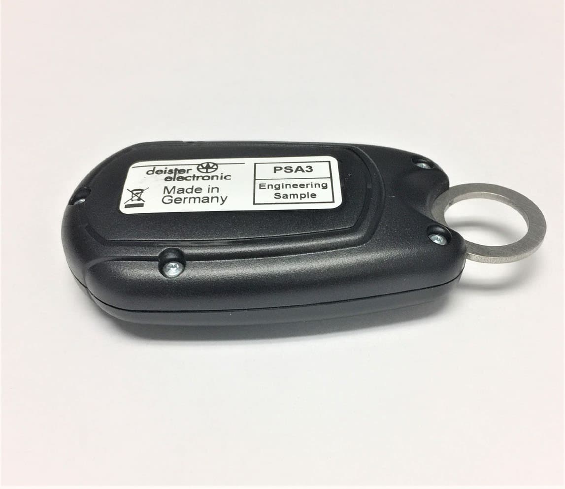
IXLPSA3
Apr 26, 2020Personal Tag Transponder
Equipment Class
DXT - Part 15 Low Power Transceiver, Rx Verified