IXLPRM5SWH2100Inductive Reader
Deister Electronic GmbH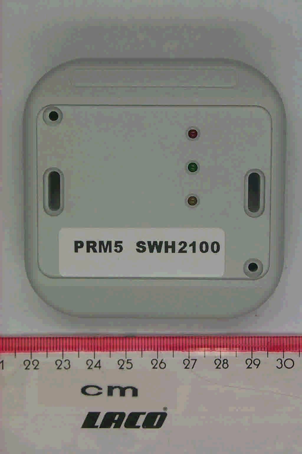
Click to zoom
Application Details
- Equipment Class
- DXX - Part 15 Low Power Communication Device Transmitter
- Date of Grant
- Feb 09, 2005
- Application Purpose
- Original Equipment
- Date of Application
- Feb 09, 2005
- Equipment Note
- Inductive Reader
- Frequency Range
- 13.56000000 - 13.56000000
- Company
- Deister Electronic GmbH
- Country
- Germany
Documents & Files
Document Text
Text extracted from the exhibit documents filed with the FCC. Open a document above to read the original.
Users Manual
1 T y c o C O N F I D E N T I A L Model SWH-2100 Contactless Smart Card 13.56 MHz Credential Reader Installation Guide Version A1 Part Number UM-092 February 2005 2 T y c o C O N F I D E N T I A L CONTENTS Introduction . . . . . . . . . . . . . . . . . . . . . . . . . . . . . . . . . . . . . . . . . . . . . . . . 3 Features . . . . . . . . . . . . . . . . . . . . . . . . . . . . . . . . . . . . . . . . . . . . . . . . . . . 4 Mounting . . . . . . . . . . . . . . . . . . . . . . . . . . . . . . . . . . . . . . . . . . . . . . . . . . 5 Installation Considerations. . . . . . . . . . . . . . . . . . . . . . . . . . . . . . . . . . . . . 6 Wiring . . . . . . . . . . . . . . . . . . . . . . . . . . . . . . . . . . . . . . . . . . . . . . . . . . . . 8 Installation Notes . . . . . . . . . . . . . . . . . . . . . . . . . . . . . . . . . . . . . . . . . . . . 9 Troubleshooting . . . . . . . . . . . . . . . . . . . . . . . . . . . . . . . . . . . . . . . . . . . . 10 Model SWH-2100 Technical Specifications . . . . . . . . . . . . . . . . . . . . . . .11 FCC Digital Device Limitations . . . . . . . . . . . . . . . . . . . . . . . . . . . . . . . 13 UL Standards Compliance . . . . . . . . . . . . . . . . . . . . . . . . . . . . . . . . . . . . 14 CE Marking . . . . . . . . . . . . . . . . . . . . . . . . . . . . . . . . . . . . . . . . . . . . . . . 15 3 T y c o C O N F I D E N T I A L INTRODUCTION The SWH-2100 Contactless Smart Card reader will read Smart Cards at a frequency of 13.56 MHz. The reading capability includes, for Smart Cards, both serial numbers and programmed sectors along with both encrypted and unencrypted ID data. Compatible standards include ISO 15693, ISO 14443A and MIFARE® sector. Refer to Table 1 for a complete list of compatible standards and data. TABLE 1.Compatible Credential Formats - Model SWH-2100 ISO 14443A (MIFARE®) Serial Number ISO 14443B Serial Number ISO 15693 Serial Number MIFARE® Sector SmartFrame® MIFARE® Sector Pass Through DESFire® Serial Number iCLASS® Serial Number Others - Future Expansion 4 T y c o C O N F I D E N T I A L FEATURES Universal compatibility with all ISO 15693 and ISO 14443A credentials (badges, disk tags and key fobs). Reads most 13.56 MHz credentials in the same reader. Electrical protection (reverse polarity diode protection on power lines) Data lines: high-speed transient voltage suppressor diodes IP65-rated sealed electronics for deployment in both interior and exterior environments Integrated reader tamper protection 5 T y c o C O N F I D E N T I A L MOUNTING Mount the single-gang backplate (with tamper magnet installed) onto the wall. FIGURE 1. Model SWH-2100 Reader Backplate (includes tamper switch magnet) NOTE Mounting holes fit standard U.S. single-width electrical box and standard European (EMEA) electrical box hole patterns. 6 T y c o C O N F I D E N T I A L Mount the reader module directly to the backplate and then snap the front cover in place as indicated in Figure 2. FIGURE 2. Mounting Assembly (including 1 optional isolation spacer) INSTALLATION CONSIDERATIONS An isolation spacer (available from Software House, part number SWH-ISOSPC) may be used to improve the read range distance when mounting the reader to a metal surface. To optimize reader range, use the number of backplates as indicated in Table 2. Use of Isolation Spacers is optional and not required for non-metal mounting surfaces. 7 T y c o C O N F I D E N T I A L Installation of two SWH-2100 readers side-by-side and back-to-back Read range is not affected if the center-to-center distance between two readers is greater than or equal to four (4) inches (101.6 mm). If the distance between the two readers is less than four inches, field interference between the two readers may result in a double-badge read. Two readers can simultaneously read the same badge or tag if the distance between the two readers is less than 4 inches, center-to-center. NOTE If two readers are being placed back-to-back on a wall less than 4 inches thick, maximum performance can be achieved by using a metal separation plate and then using isolation spacers as necessary. TABLE 2.Isolation spacer recommendation for mounting the SWH-2100 reader on metal. DistanceReading Distance No metal plate100% 4.5 cm100% 2.7 cm (3 tamper plates)85% 1.8 cm (2 tamper plates)70% 0.9 cm (1 tamper plate)50% 0 cm10% 8 T y c o C O N F I D E N T I A L WIRING The Model SWH-2100 has twelve terminals as noted in Table 3. The terminal strip is removable for easy installation and wiring. When attaching wires to the connector, strip off only the minimum insulation required (approx. 1/8'') and push the wire into the connector until the insulation is flush or inside the connector body. This is particularly critical for outdoor readers. While the reader itself is designed and protected to IP65 standards, the cable wires can potentially corrode and short together if not carefully mounted and tightly fastened in the connector body. TABLE 3. Connector Pins for Model SWH-2100 PIN #Description 1External Beeper Control 2Ground 3Power (8 to 16 VDC) 4D1 Wiegand 5D0 Wiegand 6Reserved for Future Use 7External Green LED Control 8External Red LED Control 9A - RS485 - used for Flash upgrade 10B - RS485 - used for Flash upgrade 11Tamper (Normally Closed) 12Tamper (Normally Closed) 9 T y c o C O N F I D E N T I A L Table 4 indicates maximum wiring distances per Wiegand standard with the three most common gauges of cable. INSTALLATION NOTES Unless otherwise specified in this manual, please follow these guidelines: 1. Shielded cable is recommended in electrically noisy environments. 2. You can use a local power supply for the reader. If so, don’t connect the power supply from the controller to the reader. The ground line of the local power supply must be connected to the power supply of the controller. 3. The unit needs to be operated with a power source with limited power consumption according to EN 60950-1 (2003) paragraph 2.5. 4. Use of a p…
Text truncated - open the document above for the full version.
Cover Letter(s)
deister electronic GmbH - Hermann-Bahlsen-Straße 11-13 D-30890 Barsinghausen ! IDENTIFIKATION PHOENIX TEST-LAB GmbH! SICHERHEITSTECHNIK Product Certification! VERKEHRSELEKTRONIK Königswinkel 10 ! 05105-516-01 32825 Blomberg " 05105-516217 10. Februar 2005 RE:Certification Application FCC ID:IXLPRM5SWH2100 Pursuant to Sections 0.459 of the Commission's Rule, deister electronic GmbH, hereby requests confidential treatment of information accompanying this application as outlined below: - schematic diagrams - block diagram - technical description of operation The application contains technical information which deister electronic GmbH deems to be trade secrets and proprietary. If made public, the information might be used to the disadvantage of the applicant in the market place. Thank you for your attention in this matter. (Stefan Eichler) deister electroinc GmbHHandelsregister :Bankverbindungen :Kto.-Nr.BLZ Hermann-Bahlsen-Straße 11-13Amtsger. Wennigsen HBR 1203Stadtsparkasse Barsinghausen05 304(251 512 70) 30890 BarsinghausenGeschäftsführung:Dresdner Bank Hannover76 142 02(250 800 20) ! (+49) 05105 516 01Anatoli StobbeDeutsche Bank Barsinghausen4 686 424(250 700 70) " (+49) 05105 516 217USt-IdNr. : DE 115507822Postgiro Hannover612 23-303 (250 100 30) Mitglied . BHE ®
External Photos
SWH 2100
External Photos
Annex C of test report R41092A Revision 1, Edition 2 EUT: PRM5 / SWH-2100 Manufacturer: deister electronic GmbH Examiner: Thomas KÜHNDate of issue: 07 February 2005page 1 of 1 41092A_e.jpgPRM5 / SWH-2100, front view
Internal Photos
Annex B of test report R41092A Revision 1, Edition 2 EUT: PRM5 / SWH-2100 Manufacturer: deister electronic GmbH Examiner: Thomas KÜHNDate of issue: 07 February 2005page 1 of 5 41092A_d.jpgPRM5 / SWH-2100, rear view Annex B of test report R41092A Revision 1, Edition 2 EUT: PRM5 / SWH-2100 Manufacturer: deister electronic GmbH Examiner: Thomas KÜHNDate of issue: 07 February 2005page 2 of 5 41092A_c.jpgPRM5 / SWH-2100, main PCB, top view Annex B of test report R41092A Revision 1, Edition 2 EUT: PRM5 / SWH-2100 Manufacturer: deister electronic GmbH Examiner: Thomas KÜHNDate of issue: 07 February 2005page 3 of 5 41092A_b.jpgPRM5 / SWH-2100, main PCB, bottom view Annex B of test report R41092A Revision 1, Edition 2 EUT: PRM5 / SWH-2100 Manufacturer: deister electronic GmbH Examiner: Thomas KÜHNDate of issue: 07 February 2005page 4 of 5 41092A_f.jpgPRM5 / SWH-2100, antenna PCB, top view Annex B of test report R41092A Revision 1, Edition 2 EUT: PRM5 / SWH-2100 Manufacturer: deister electronic GmbH Examiner: Thomas KÜHNDate of issue: 07 February 2005page 5 of 5 41092A_a.jpgPRM5 / SWH-2100, antanna PCB, bottom view
Test Report
Königswinkel 10 32825 Blomberg Germany Phone+49 5235 9500-0 Fax+49 5235 9500-10 TEST REPORT Test Report Reference: R41092A Revision 1, Edition 2 Equipment under Test: PRM5 / SWH-2100 Serial Number: - Applicant: deister electronic GmbH Manufacturer: deister electronic GmbH Test Laboratory (CAB) accredited by DATech e.V. in compliance with DIN EN ISO/IEC 17025 under the Reg. No. DAT-P-105/99-21 and listed by FCC 31040/SIT1300F2 TEST REPORT REFERENCE: R41092A Revision 1, Edition 2 Examiner: Thomas KÜHNDate of issue: 07 February 2005Page 2 of 30 Contents:Page 1 IDENTIFICATION.....................................................................................................................................3 1.1 APPLICANT.....................................................................................................................................3 1.2 MANUFACTURER..........................................................................................................................3 1.3 DATES.............................................................................................................................................3 1.4 TEST LABORATORY......................................................................................................................4 1.5 RESERVATION...............................................................................................................................4 1.6 NORMATIVE REFERENCES..........................................................................................................4 1.7 TEST RESULTS..............................................................................................................................4 2 TECHNICAL DATA OF EQUIPMENT......................................................................................................5 2.1 DEVICE UNDER TEST...................................................................................................................5 2.2 PEREPHERY DEVICES..................................................................................................................5 2.3 SPECIAL EMC MEASURES...........................................................................................................5 3 OPERATIONAL STATES AND PHYSICAL BOUNDARIES.....................................................................6 4 LIST OF TEST MODULES.......................................................................................................................7 4.1 EMISSION.......................................................................................................................................7 5 METHOD OF MEASUREMENT...............................................................................................................8 5.1 CONDUCTED EMISSIONS ON POWER SUPPLY LINES (150 kHz to 30 MHz)...........................8 5.2 RADIATED EMISSIONS 9 kHz to 30 MHz......................................................................................9 5.3 RADIATED EMISSIONS 30 MHz to 1 GHz.....................................................................................11 5.4 FREQUENCY STABILITY WITH RESPECT TO AMBIENT TEMPERATURE AND SUPPLY VOLTAGE....................................................................................13 6 TEST RESULTS EMISSION TEST..........................................................................................................15 6.1 CONDUCTED EMISSION MEASURMENT ON AC MAINS (150 kHz to 30 MHz)..........................15 6.2 PRELIMINARY RADIATED EMISSION TEST (9 kHz to 30 MHz)..................................................17 6.3 PRELIMINARY RADIATED EMISSION TEST (30 MHz to 1 GHz).................................................19 6.4 FINAL RADIATED EMISSION TEST (9 kHz to 30 MHz)................................................................21 6.5 FINAL RADIATED EMISSION TEST (30 MHz to 1 GHz)...............................................................22 6.6 OCCUPIED BANDWIDTH...............................................................................................................24 6.7 FREQUENCY TOLLERANCE.........................................................................................................25 7 TEST EQUIPMENT AND ANCILLARIES USED FOR TESTS.................................................................26 8 LIST OF ANNEXES..................................................................................................................................30 TEST REPORT REFERENCE: R41092A Revision 1, Edition 2 Examiner: Thomas KÜHNDate of issue: 07 February 2005Page 3 of 30 1IDENTIFICATION 1.1APPLICANT Name:deister electronic GmbH Address:Hermann-Bahlsen-Straße 11 – 13 30890 Barsinghausen Country:Germany Name for contact purposes:Mr. Stefan Eichler Tel:+49 51 05 516-129 Fax:+49 51 05 516-266 e-mail address:[email protected] 1.2MANUFACTURER Name:deister electronic GmbH Address:Hermann-Bahlsen-Straße 11 – 13 30890 Barsinghausen Country:Germany Name for contact purposes:Mr. Stefan Eichler Tel:+49 51 05 516-129 Fax:+49 51 05 516-266 e-mail address:[email protected] 1.3DATES Date of receipt of test sample:01 December 2004 Start of test:02 December 2004 End of test:07 January 2005 TEST REPORT REFERENCE: R41092A Revision 1, Edition 2 Examiner: Thomas KÜHNDate of issue: 07 February 2005Page 4 of 30 1.4TEST LABORATORY The tests were carried out at:PHOENIX TESTLAB GmbH Königswinkel 10 D-32825 BlombergPhone: +49 (0) 52 35 / 95 00-0 GermanyFax:+49 (0) 52 35 / 95 00-10 accredited by DATech e.V. in compliance with DIN EN ISO/IEC 17025 under Reg. No. DAT-P-105/99-21 and listed by FCC 31040/SIT1300F2. Test engineer:Thomas KÜHN07 February 2005 NameSignatureDate Test report checked:Bernd STEINER07 February 2005 NameSignatureDate Stamp 1.5RESERVATION T h i s t e s t r e p o r t i s o n l y v a l i d i n i t s o r i g i n a l f o r m. Any reproduction of its contents without written permission of the accredited test …
Text truncated - open the document above for the full version.
Test Setup Photos
Annex A of test report R41092A Revision 1, Edition 2 EUT: PRM5 / SWH-2100 Manufacturer: deister electronic GmbH Examiner: Thomas KÜHNDate of issue: 07 February 2005page 1 of 7 41092A_3.jpgPRM5 / SWH-2100, test set-up shielded chamber Annex A of test report R41092A Revision 1, Edition 2 EUT: PRM5 / SWH-2100 Manufacturer: deister electronic GmbH Examiner: Thomas KÜHNDate of issue: 07 February 2005page 2 of 7 41092A_2.jpgPRM5 / SWH-2100, test set-up shielded chamber Annex A of test report R41092A Revision 1, Edition 2 EUT: PRM5 / SWH-2100 Manufacturer: deister electronic GmbH Examiner: Thomas KÜHNDate of issue: 07 February 2005page 3 of 7 41092A_12.jpgPRM5 / SWH-2100, test set-up fully anechoic chamber Annex A of test report R41092A Revision 1, Edition 2 EUT: PRM5 / SWH-2100 Manufacturer: deister electronic GmbH Examiner: Thomas KÜHNDate of issue: 07 February 2005page 4 of 7 41092A_10.jpgPRM5 / SWH-2100, test set-up fully anechoic chamber Annex A of test report R41092A Revision 1, Edition 2 EUT: PRM5 / SWH-2100 Manufacturer: deister electronic GmbH Examiner: Thomas KÜHNDate of issue: 07 February 2005page 5 of 7 41092A_6.jpgPRM5 / SWH-2100, test set-up outdoor test site Annex A of test report R41092A Revision 1, Edition 2 EUT: PRM5 / SWH-2100 Manufacturer: deister electronic GmbH Examiner: Thomas KÜHNDate of issue: 07 February 2005page 6 of 7 41092A_8.jpgPRM5 / SWH-2100, test set-up open area test site Annex A of test report R41092A Revision 1, Edition 2 EUT: PRM5 / SWH-2100 Manufacturer: deister electronic GmbH Examiner: Thomas KÜHNDate of issue: 07 February 2005page 7 of 7 41092A_1.jpgPRM5 / SWH-2100, test set-up climatic chamber
Contact Information
Applicant
Nicolas Stobbe(Head of Business Development)
Technical Contact
deister electronic GmbHStefan Eichler
[email protected]+49 (0) 510551601
Hermann-Bahlsen-Str. 11-13 · Barsinghausen · Germany
Non-Technical Contact
deister electronic GmbHStefan Eichler
[email protected]+49 (0) 510551601
Test Firm
Phoenix TestLab GmbHH. Altmaier
Technical Specifications
| # | Rule Parts | Frequency Range | Power Output | Tolerance |
|---|---|---|---|---|
| 1 | 15C | 13.56 MHz - 13.56 MHz | - | 0.0100000000 % |
Other Applications from Deister Electronic GmbH
IXLPRT6KPT6
Oct 07, 2024RFID Reader
Equipment Class
DXX - Part 15 Low Power Communication Device Transmitter
IXLSWH6000PCB
Oct 07, 2024RFID Reader
Equipment Class
DXX - Part 15 Low Power Communication Device TransmitterIXLPRDI4IC
Nov 01, 2021Access Control Reader Module
Equipment Class
DCD - Part 15 Low Power Transmitter Below 1705 kHz
IXLRHX
Aug 05, 2020Door Lock LF Read Head
Equipment Class
DXT - Part 15 Low Power Transceiver, Rx Verified
IXLPSA3
Apr 26, 2020Personal Tag Transponder
Equipment Class
DXT - Part 15 Low Power Transceiver, Rx Verified