IXLTPU4030RFID Transponder
Deister Electronic GmbH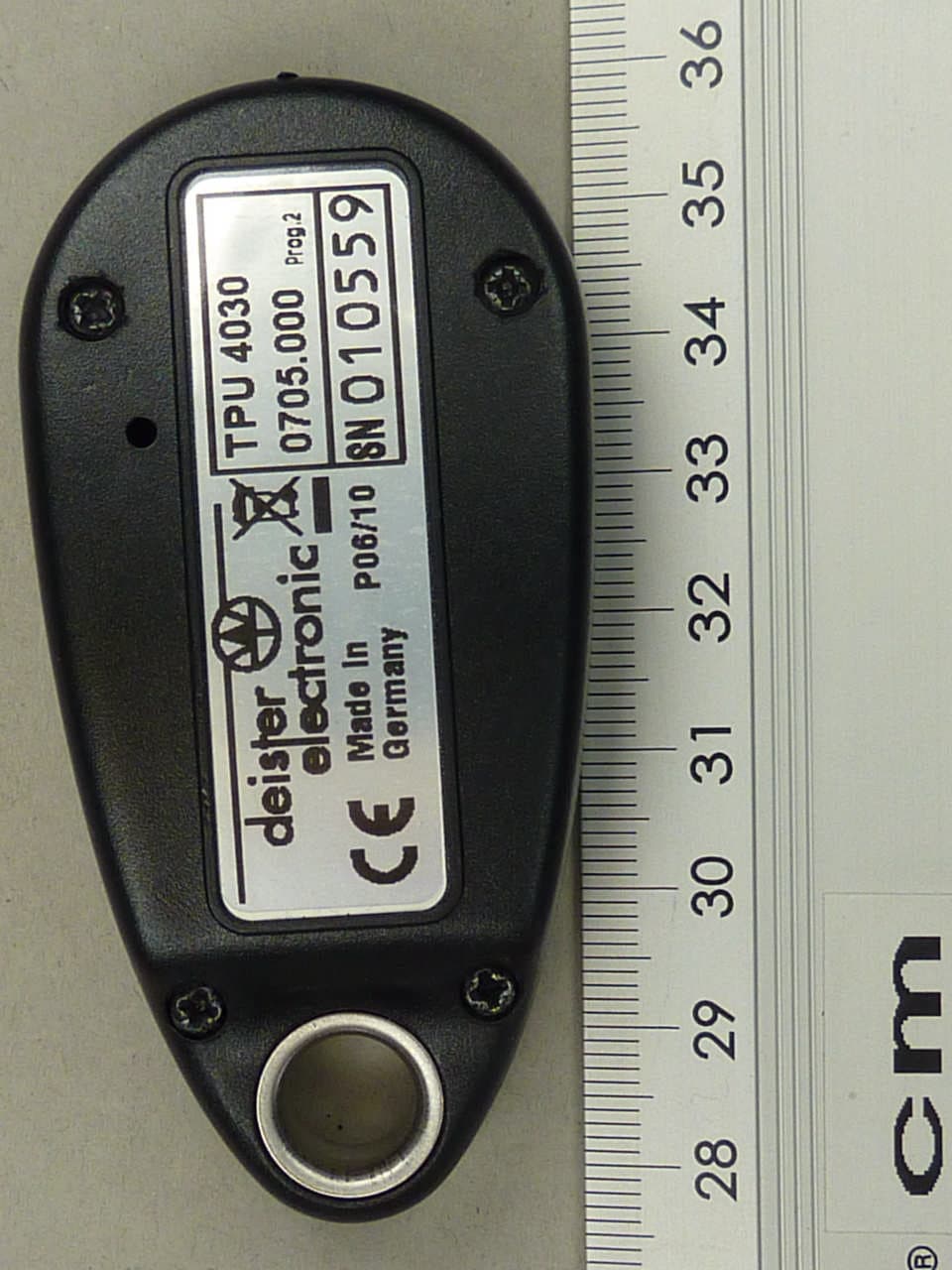
Click to zoom
Application Details
- Equipment Class
- DSC - Part 15 Security/Remote Control Transmitter
- Date of Grant
- Jan 09, 2012
- Application Purpose
- Original Equipment
- Date of Application
- Jan 09, 2012
- Equipment Note
- RFID Transponder
- Frequency Range
- 433.00000000 - 433.00000000
- Company
- Deister Electronic GmbH
- Country
- Germany
Documents & Files
Document Text
Text extracted from the exhibit documents filed with the FCC. Open a document above to read the original.
Users Manual
Art. #TBAm_en_tpu-4030-pcb_pro_v111115_de_bf TPU 4030 PCB User Manual Content 1. Technical Data............................................................5 2. Mechanical Dimensions..............................................6 3. General Information...................................................6 4. Activating the Transponder........................................7 5. Acoustic Signal............................................................7 6. Battery Monitoring......................................................7 2m_en_tpu-4030-pcb_pro_v111115_de_bf Regulatory Notices Europe Hereby, deister electronic GmbH declares that this equipment - if used according to the instructions - is in compliance with the essential requirements and other relevant provisions of the RTTE Directive 1999/5/EC. A full declaration of conformity can be requested at: [email protected] Approved for use in all European countries. FCC Warning This device complies with Part 15 of the FCC rules. Operation is subject to the following two conditions: (1) This device may not cause harmful interference, and (2) this device must accept any interference received, including interference that may cause undesired operation. CAUTION: Changes or modifications not expressly approved by the manufacturer could void the user’s authority to operate this equipment. Industry Canada This Class A digital apparatus complies with Canadian ICES-003. Cet appareil numérique de la classe A est conforme à la norme NMB-003 du Canada. This device complies with Industry Canada licence-exempt RSS standard(s). Operation is subject to the following two conditions: (1) this device may not cause interference, and (2) this device must accept any interference, including interference that may cause undesired operation of the device. Le présent appareil est conforme aux CNR d'Industrie Canada applicables aux appareils radio exempts de licence. L'exploitation est autorisée aux deux conditions suivantes : (1) l'appareil ne doit pas produire de brouillage, et (2) l'utilisateur de l'appareil doit accepter tout brouillage radioélectrique subi, même si le brouillage est susceptible d'en compromettre le fonctionnement. Note: When installing the board into other devices, under no circumstances should an electrical connection be established. m_en_tpu-4030-pcb_pro_v111115_de_bf 3 © Copyright 2011 by deister electronic GmbH Disclaimer deister electronic GmbH is not able to supervise the observance of the instructions given in this manual as well as the conditions and methods used during installation, operation and maintenance of the electronic devices and components respectively. Therefore we disclaim liability and reject responsibility for any losses, damages or costs that are caused by misapplication, installation, handling errors or faulty operation or related to the above in any other way. All our products are subject to current advancement, therefore we reserve the right for modifications without prior notice. All rights reserved. No part of this publication may be reproduced, stored in a retrieval system, or transmitted, in any form or by any means, electronic, mechanical, photocopying, recording, or otherwise, without prior written permission of deister electronic GmbH. deister electronic GmbH reserves the right to make changes to any and all parts of this documentation without obligation to notify any person or entity of such changes. deister electronic GmbH Hermann-Bahlsen Str. 11 30890 Barsinghausen Germany Phone: +49 (0) 51 05 - 51 61 11 Fax:+49 (0) 51 05 - 51 62 17 E-Mail: [email protected] Web:www.deister.com 4m_en_tpu-4030-pcb_pro_v111115_de_bf 1. Technical Data Dimensions: mm (inch) W x H x D31.8 x 54.4 x 10 (1.25 x 2.14 x 0.41) Operating Temperature: °C (°F)5 ... 50 (41 ... 122) Relative Humidity:5 %...95 %, non-condensing Power Requirement:1x CR 2450 Frequency:8 kHz, 125 kHz, 433 MHz Reading Distance: in m (ft.)up to 10 (32.8) OTP: (e.g. Formats up to 64 Bit) Fixcode:(e.g. 32 Bit) Conformity:EN 50364 EN 301489 Air interface (EU)EN 300330 Air interface (US)FCC Part 15 m_en_tpu-4030-pcb_pro_v111115_de_bf 5 2. Mechanical Dimensions All dimensions in mm [inch]. 3. General Information TPU 4030 is an active transponder, which was developed to be used in combination with Amantag Compact and / or PRX5 reader or ADA (Amantag deactivator). The transponder has three interfaces for communication with readers. •Receiving via 8,1 kHz •Sending via 433 MHz •Sending and receiving via125 kHz (passive modulation) Amantag Compact readers are using 8.1 kHz and 433 MHz frequencies. These low- frequency fields are generated by the reader and serve to activate the transponder and to communicate with the transponder. Messages from the transponder to the reader are transmitted via 433 MHz. Once a transponder is brought into the sphere of the low frequecy field, it is activated and gets recorded by the reader. Reader and transponder will remain in a constant communication with each other until the transponder leaves the field. The transponder can also send out an acoustic signal when it is detected by the reader. An 125 kHz interface is used for data exchange with PRX 5 reader or ADA. After activation, the transponder sends data to the reader for about 3 seconds. To activate the transponder again, it must first be removed from the reader field and then brought in again. 6m_en_tpu-4030-pcb_pro_v111115_de_bf 4. Activating the Transponder For transportation, the transponders are set to transport mode. Before use. they must be activated. The activation is done by an Amantag compact reader. The DIP switch B6 needs to be set to ON position. Attention! Possibly, the field strength must be increased. Therefore, set DIP switch B1 to B4 to “ON” position. After configuration, the transponder should be placed close to the reader (it requires high power to wake up the transponder from transport mode). As long as the switch B6 is in ON position, there is no reaction from the …
Text truncated - open the document above for the full version.
Cover Letter(s)
Handelsregister: Amtsger. Hannover HRB 101264Bankkonten:Kto.Nr.: BLZ:IBAN:SWIFT-BIC: Geschäftsführung: Anatoli StobbeStadtsparkasse Barsinghausen10 53 04251 512 70DE 45 2515 1270 0000 1053 04 NOLA DE 21 BAH USt-IdNr.: DE 115507822Dresdner Bank Hannover76 14 20 2250 800 20 DE 94 2508 0020 0761 4202 00DRES DE FF 250 USt-Nr.: 23/202/38748Postbank Hannover61 22 33 03250 100 30 WEEE-Reg.-Nr.: DE 96 95 94 78Deutsche Bank Barsinghausen46 86 42 4250 700 70DE 30 2507 0070 0468 6424 00DEUT DE 2H PHOENIX TEST-LAB GmbH Product Certification Königswinkel 10 32825 Blomberg 15. September 2011 RE: Certification Application FCC ID:IXLTPU4030 Pursuant to Sections 0.457 and 0.459 of the Commission's Rule, deister electronic GmbH, hereby requests confidential treatment of information accompanying this application as outlined below: - schematic diagrams - block diagram - technical description of operation The application contains technical information which deister electronic GmbH deems to be trade secrets and proprietary. If made public, the information might be used to the disadvantage of the applicant in the market place. Thank you for your attention in this matter. (Stefan Eichler) Security & Safety Ident & Automation deister electronic GmbH Hermann-Bahlsen-Str. 11 30890 Barsinghausen Germany E-mail: [email protected] Web: www.deister.com Tel.: +49 (0) 51 05 - 51 61 11 Fax: +49 (0) 51 05 - 51 62 17 deister electronic GmbH ⋅ Hermann-Bahlsen-Str. 11 ⋅ D-30890 Barsinghausen
External Photos
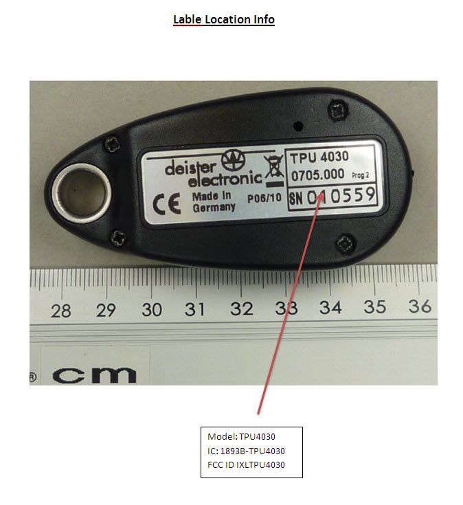
ANNEX C:EXTERNAL PHOTOS OF THE EUT Examiner:Thomas KÜHNTest Report No.:F111947E2 Date of issue:05 January 2012Order No.:11-111947page1 of3 111947_c.JPG: TPU 4030, 3-D view 1 ANNEX C:EXTERNAL PHOTOS OF THE EUT Examiner:Thomas KÜHNTest Report No.:F111947E2 Date of issue:05 January 2012Order No.:11-111947page2 of3 111947_d.JPG: TPU 4030, 3-D view 2 ANNEX C:EXTERNAL PHOTOS OF THE EUT Examiner:Thomas KÜHNTest Report No.:F111947E2 Date of issue:05 January 2012Order No.:11-111947page3 of3 111947_a.JPG: TPU 4030, type plate view
Internal Photos
ANNEX B:INTERNAL PHOTOS OF THE EUT Examiner:ThomasKÜHNTest Report No.:F111947E2 Date of issue:05 January 2012Order No.:11-111947page1 of4 111947_h.JPG: TPU 4030 internal view ANNEX B:INTERNAL PHOTOS OF THE EUT Examiner:ThomasKÜHNTest Report No.:F111947E2 Date of issue:05 January 2012Order No.:11-111947page2 of4 111947_e.JPG: TPU 4030, PCB, top view ANNEX B:INTERNAL PHOTOS OF THE EUT Examiner:ThomasKÜHNTest Report No.:F111947E2 Date of issue:05 January 2012Order No.:11-111947page3 of4 111947_g.JPG: TPU 4030, PCB, top view, battery removed ANNEX B:INTERNAL PHOTOS OF THE EUT Examiner:ThomasKÜHNTest Report No.:F111947E2 Date of issue:05 January 2012Order No.:11-111947page4 of4 111947_f.JPG: TPU 4030, PCB, bottom view
Test Report
ANNEX ESPURIOUS EMISSIONS WITHOUT HOUSING Test engineer:Thomas KÜHNReport Number:F111947E2 Date of issue:05 January 2012Order Number:11-111947page1 of 2 1 Final radiated emission measurement (30 MHz to 1 GHz) Ambient temperature20 °CRelative humidity50 % Position of EUT:The EUT was set-up on a non-conducting table of a height of 0.8 m. The distance between EUT and antenna was 3 m. Cable guide:No cable was connected to the EUT. For detail information of test set-up refer to the photographs in annex A of this test report. Test record:EUT without housing, allresults are shown in the following. Supply voltage:During all measurements the EUT was supplied by a new internal battery. The results of the standard subsequent measurement on the open area test site are indicated in the table below. The limits as well as the measured results (levels) refer to the above mentioned standard while taking account of the specified requirements for a 3 m measuring distance. The measurement time with the peak detector is 1 second. Result measured with the peak detector and corrected to average: Spurious emissions outside restricted bands Frequency MHz Result dBμV/m Limit dBμV/m Margin dB Readings dBμV Correction factor dB Antenna factor dB/m Cable loss dB Height cm Azimuth deg Pol.Position 433.65378.480.82.467.4-7.816.42.4111.0271.0Vert.2 477.2059.860.851.0-1.7-7.816.92.4209.01. 0Vert.2 867.30660.660.80.242.8-7.822.23.4111.046.0Vert2 Measurement uncertainty+2.2 dB /-3.6 dB The test results were calculated with the following formula: Result [dBμV/m] = reading [dBμV] + cable loss [dB] + antenna factor [dB/m] +correction factor [dB]. Test:Passed TEST EQUIPMENT USED FOR THE TEST: 14- 20 ANNEX ESPURIOUS EMISSIONS WITHOUT HOUSING Test engineer:Thomas KÜHNReport Number:F111947E2 Date of issue:05 January 2012Order Number:11-111947page2 of 2 2 Final radiated emission measurement (1 GHz to 4.5 GHz) Ambient temperature20 °CRelative humidity57 % Position of EUT:The EUT was set-up on a non-conducting table of a height of 0.8 m. The distance between EUT and antenna was 3 m. Cable guide:No cable was connected to the EUT. For detail information of test set-up refer to the photographs in annex A of this test report. Test record:EUT without housing, allresults are shown in the following. Supply voltage:During all measurements the EUT was supplied by a new internal battery. Resolution bandwidth:For all measurements a resolution bandwidth of 1 MHz was used. Result measured with the peak detector: Frequency GHz Corr. value dBμV/m Limit dBμV/m Margin dB Readings dBμV Antenna factor 1/m Preamp dB Cable loss dB Height cm Pol.Restr. Band Position 1300.95949.374.024.748.125.026.52.7150Hor.Yes1 1734.61257.174.016.953.926.626.53.1150Vert.No2 2168.26540.974.033.136.227.726.53.5150Vert.No3 2601.91847.274.026.841.128.626.43.9150Vert.No3 3035.57142.774.031.334.530.326.44.3150Vert.No3 3469.22444.274.029.835.031.126.34.4150Vert.No3 3902.87742.774.031.331.332.826.14.7150Hor.Yes1 4336.53042.174.031.931.032.025.95.0150Hor.Yes1 Measurement uncertainty+2.2 dB /-3.6 dB Result measured with the peak detector and converted to average: Frequency GHz Corr. value dBμV/m Limit dBμV/m Margin dB Readings dBμV Corr. factor Antenna factor 1/m Preamp dB Cable loss dB Height cm Pol.Restr. Band Position 1300.95941.554.012.548.1-7.825.026.52.7150Hor.Yes1 1734.61249.360.811.553.9-7.826.626.53.1150Vert.No2 2168.26533.160.827.736.2-7.827.726.53.5150Vert.No3 2601.91839.460.821.441.1-7.828.626.43.9150Vert.No3 3035.57134.960.825.934.5-7.830.326.44.3150Vert.No3 3469.22436.460.824.435.0-7.831.126.34.4150Vert.No3 3902.87734.954.019.131.3-7.832.826.14.7150Hor.Yes1 4336.53034.354.019.731.0-7.832.025.95.0150Hor.Yes1 Measurement uncertainty+2.2 dB /-3.6 dB The test results were calculated with the following formula: Result[dBμV/m] = reading [dBμV] + cable loss [dB] + antenna factor [dB/m]– preamp. [dB] + correction factor [dB] Test:Passed TEST EQUIPMENT USED FOR THE TEST: 29, 31- 34, 36, 73, 143
Test Report
Königswinkel 10 32825 Blomberg Germany Phone:+49 (0) 52 35 95 00-0 Fax:+49 (0) 52 35 95 00-10 Test Report Report Number: F111947E2 Applicant: deister electronic GmbH Manufacturer: deister electronic GmbH Equipment under Test (EUT): TPU 4030 Laboratory (CAB) accredited by Deutsche Gesellschaft für Akkreditierung mbH in compliance with DIN EN ISO/IEC 17025 under the Reg. No. DGA-PL-105/99-22, FCC Test site registration number 90877and Industry Canada Test site registration IC3469A-1 Test engineer:Thomas KÜHNReport Number:F111947E2 Date of issue:05 January 2012Order Number:11-111947page2 of31 REFERENCES [1]ANSI C63.4-2009American National Standard for Methods of Measuring of Radio-Noise Emissions from Low-Voltage Electrical and Electronic Equipment in the Range of 9 kHz to 40 GHz. [2]FCC CFR 47 Part 15 (August 2011)Radio Frequency Devices [3]RSS-210 Issue 8 (December 2010)Licence-exempt Radio Apparatus(All FrequencyBands): Category I Equipment [4]RSS-GenIssue 3 (December 2010)General Requirements and Information for the Certification of Radio Apparatus [6]Publication Number 913591 (March 2007)Measurement of radiated emissions at the edge of the band for a Part 15 RF Device TEST RESULT The requirements of the tests performed as shown in the overview (clause4) werefulfilled by the equipment under test. The complete test results are presented in the following. RESERVATION T h i s t e s t r e p o r t i s o n l y v a l i d i n i t s o r i g i n a l f o r m . Any reproduction of its contents in extracts without written permission of the accredited test laboratory PHOENIX TESTLAB GmbH is prohibited. The test results herein refer only to the tested sample. PHOENIX TESTLAB GmbH is not responsible for any generalizations or conclusions drawn from these test results concerning further samples. Any modification of the tested samples is prohibited and leads to the invalidity of this test report. Each page necessarily contains the PHOENIX TESTLAB Logo and the TEST REPORT NUMBER. Test engineer: Thomas KÜHN05 January 2012 NameSignatureDate Authorized reviewer: Bernd STEINER05 January 2012 Name Signature Date Test engineer:Thomas KÜHNReport Number:F111947E2 Date of issue:05 January 2012Order Number:11-111947page3 of31 Contents:Page 1IDENTIFICATION...................................................................................................................4 1.1Applicant............................................................................................................................4 1.2Manufacturer.....................................................................................................................4 1.3Test laboratory...................................................................................................................4 1.4EUT (Equipment Under Test)............................................................................................5 1.5Technical data of equipment..............................................................................................5 1.6Dates................................................................................................................................. 6 2OPERATIONAL STATES.......................................................................................................6 3ADDITIONAL INFORMATION................................................................................................7 4OVERVIEW............................................................................................................................7 5TEST RESULTS....................................................................................................................8 5.1Calculation of the measurement results.............................................................................8 5.220 dB bandwidth..............................................................................................................10 5.2.1Method of measurement (20 dB bandwidth)...........................................................10 5.2.2Test results (20 dB bandwidth)...............................................................................11 5.3Band-edge compliance....................................................................................................12 5.3.1Method of measurement (Band-edge compliance (radiated))................................. 12 5.3.2Test results(Band-edgecompliance (radiated)).....................................................13 5.4Transmission time control................................................................................................15 5.4.1Method of measurement (transmission time control)...............................................15 5.4.2Test results (transmission time control)................................................................... 16 5.5Radiated emissions.........................................................................................................17 5.5.1Method of measurement (Radiated emissions).......................................................17 5.5.2Test results (radiated emissions)............................................................................24 5.5.2.1Preliminary radiated emission measurement (9 kHz to 30 MHz)........................24 5.5.2.2Preliminary radiated emission measurement (30 MHz to 4.5 GHz)....................26 5.5.2.3Final radiated emission measurement (30 MHz to 1 GHz)................................. 28 5.5.2.4Final radiated emission measurement (1 GHz to 4.5 GHz)................................. 29 6TEST EQUIPMENT AND ANCILLARIES USED FOR TESTS..............................................30 7REPORT HISTORY.............................................................................................................30 8LIST OF ANNEXES..............................................................................................................31 Test engineer:Thomas KÜHNReport Number:F111947E2 Date of issue:05 January 2012O…
Text truncated - open the document above for the full version.
Test Setup Photos
ANNEX A: TEST SETUP PHOTOS Examiner:Thomas KÜHNTest Report No.:F111947E2 Date of issue:05 January 2012Order No.:11-111947page1 of7 111947_14.JPG: TPU 4030 with housing, test setup fully anechoic chamber (pos. 3) ANNEX A: TEST SETUP PHOTOS Examiner:Thomas KÜHNTest Report No.:F111947E2 Date of issue:05 January 2012Order No.:11-111947page2 of7 111947_2.JPG: TPU 4030 without housing, test setup fully anechoic chamber (pos. 2) ANNEX A: TEST SETUP PHOTOS Examiner:Thomas KÜHNTest Report No.:F111947E2 Date of issue:05 January 2012Order No.:11-111947page3 of7 111947_16.JPG: TPU 4030 with housing, test setup fully anechoic chamber (pos.1) ANNEX A: TEST SETUP PHOTOS Examiner:Thomas KÜHNTest Report No.:F111947E2 Date of issue:05 January 2012Order No.:11-111947page4 of7 111947_12.JPG: TPU 4030 without housing, test setup fully anechoic chamber (pos. 2) ANNEX A: TEST SETUP PHOTOS Examiner:Thomas KÜHNTest Report No.:F111947E2 Date of issue:05 January 2012Order No.:11-111947page5 of7 111947_5.JPG: TPU 4030 without housing, test setup fully anechoic chamber (pos. 3) ANNEX A: TEST SETUP PHOTOS Examiner:Thomas KÜHNTest Report No.:F111947E2 Date of issue:05 January 2012Order No.:11-111947page6 of7 111947_17.JPG: TPU 4030 with housing, test setup fully anechoic chamber(pos. 3) ANNEX A: TEST SETUP PHOTOS Examiner:Thomas KÜHNTest Report No.:F111947E2 Date of issue:05 January 2012Order No.:11-111947page7 of7 111947_8.JPG: TPU 4030 without housing, test setup open area test site (pos. 1)
Contact Information
Applicant
Nicolas Stobbe(Head of Business Development)
Test Firm
PHOENIX TESTLAB GmbHHolger Bentje
Technical Specifications
| # | Rule Parts | Frequency Range | Power Output |
|---|---|---|---|
| 1 | 15.231 | 433 MHz - 433 MHz | - |
Other Applications from Deister Electronic GmbH
IXLPRT6KPT6
Oct 07, 2024RFID Reader
Equipment Class
DXX - Part 15 Low Power Communication Device Transmitter
IXLSWH6000PCB
Oct 07, 2024RFID Reader
Equipment Class
DXX - Part 15 Low Power Communication Device TransmitterIXLPRDI4IC
Nov 01, 2021Access Control Reader Module
Equipment Class
DCD - Part 15 Low Power Transmitter Below 1705 kHz
IXLRHX
Aug 05, 2020Door Lock LF Read Head
Equipment Class
DXT - Part 15 Low Power Transceiver, Rx Verified
IXLPSA3
Apr 26, 2020Personal Tag Transponder
Equipment Class
DXT - Part 15 Low Power Transceiver, Rx Verified