IXM-DLGBR01U.S. Robotics MAXg ADSL Gateway
Universal Scientific Industrial Co., Ltd.
Click to zoom
Application Details
- Equipment Class
- DTS - Digital Transmission System
- Date of Grant
- Jul 04, 2005
- Application Purpose
- Original Equipment
- Date of Application
- Jul 04, 2005
- Equipment Note
- U.S. Robotics MAXg ADSL Gateway
- Frequency Range
- 2412.00000000 - 2462.00000000
- Country
- Taiwan
Documents & Files
Document Text
Text extracted from the exhibit documents filed with the FCC. Open a document above to read the original.
Users Manual
Wireless MAXg ADSL Gateway User Guide Home Installation Configuration Help Introduction Features Warranty Copyright Regulatory Thank you for purchasing a U.S. Robotics Wireless MAXg ADSL Gateway (Model 9108), and welcome to its User Guide. The Wireless MAXg ADSL gateway is a tool for high-speed Internet access, using cable connections or highly-secure wireless communications. The gateway also supports a USB printer, allowing all machines in your local network to share a printer. This User Guide details aspects of your gateway: Installation, Setup and Uninstallation: Complete instructions on how to install and configure your gateway. Configuration: Feature-level discussion of the gateway's Web User Interface (WUI), with examples. Help: Tutorials, troubleshooting, support, and a glossary. Technical Support For current product support and contact information, go to the U.S. Robotics Web site at: http://www.usr.com/support R46.1028.00 rev 1.0 6/05 © 2004-2005 U.S. Robotics Corporation. 第 1 頁,共 1 頁U.S. Robotics Wireless MAXg ADSL Gateway User Guide 2005/7/4file://C:\Documents%20and%20Settings\ivonne\Local%20Settings\Temp\Rar$EX50.937\inde... Wireless MAXg ADSL Gateway User Guide Home Installation Configuration Help Introduction Features Warranty Copyright Regulatory Notes about Your Gateway Features The gateway's MAXg feature provides a maximum speed of up to 125 Mbps, delivering large files like MP3s, digital photos, and digital video through your network fast and efficiently. And with MAXg, your network is protected with a maximum security suite of capabilities, including Wi-Fi Protected Access (WPA), WPA2/802.11i (AES Encryption), MAC address authentication, and more. In addition to providing state-of-the-art wireless connectivity, your MAXg gateway includes an integrated print server, allowing you to share your USB printer with other computers on your network and a 4-Port Ethernet switch for connecting Ethernet devices. Firewall - Stateful Inspection The U.S. Robotics Wireless MAXg ADSL Gateway provides firewall stateful inspection for intrusion detection. The gateway tracks all packets originating from the LAN and records each connection's address pair and the TCP/UDP port pairs. When receiving TCP/UDP packets from the Internet, the IP addresses and port numbers must match the tracking records. Otherwise, the gateway drops the packet. For ICMP packets, only outgoing ICMP request packets originating from the LAN are forwarded to the Internet, and its related incoming ICMP reply packets from the WAN side are allowed to come into the LAN. For example, you can ping any device on the Internet from a computer on the LAN, but you cannot ping the gateway or any LAN device from the Internet. Also, the gateway does not let ICMP redirect packets in, since they could be used to reroute traffic through attacking machines. The only exception to the above firewall rules occurs when remote technical support access is explicitly allowed by the local user. The gateway then responds to ping request packets and allows remote access to the gateway's Web User Interface (WUI). The gateway firewall also prevents LAND attacks and SYN floods: SYN floods: the gateway firewall drops all unsolicited TCP SYN requests received from the Internet. Land attacks: this type of attack forces a victim machine into an unending loop. The gateway firewall can prevent such attacks by disallowing any packets with the same source and destination address. Security - Remote and Local Access Accounts The U.S. Robotics Wireless MAXg ADSL Gateway WUI provides a local admin account, a local non-administrative user account, and a remote technical support account, all with password protection. The support account allows the local administrative user to 第 1 頁,共 2 頁U.S. Robotics Wireless MAXg ADSL Gateway User Guide 2005/7/4file://C:\Documents%20and%20Settings\ivonne\Local%20Settings\Temp\Rar$EX60.547\featu... explicitly let a remote technician access the gateway's WUI. The user account can view the configuration parameters but not change them. The support account does not work in bridge mode since there is no public IP address assigned to the gateway. The remote technical support user can read/write the configuration but cannot change security settings. When remote access security is enabled by a local administrator, the remote user can access the modem via telnet or a browser from the Internet, but not from the LAN. The maximum length for user names and passwords is 15 characters. DHCP Server The gateway provides DHCP server service over the LAN interface when the network operating mode is set to PPPoE, PPPoA, MER or IPoA mode. When enabled, the DHCP server responds to DHCP request packets from LAN devices and assigns: An unused IP address within the start-end IP address range configured by the user to the LAN device. The gateway's LAN interface IP address as the primary DNS server address to the LAN device. The ADSL gateway performs DNS relay between the LAN device and the real DNS server at the remote service provider site. The gateway's LAN interface IP address as the default gateway to the LAN device. DHCP Client The gateway provides DHCP client service for each Internet interface operating in the MER network operating mode. If enabled, the DHCP client requests the WAN interface IP address, primary and secondary DNS server addresses, and default gateway from the DHCP server at the service provider site. If the DHCP client function is disabled, the user must manually configure the WAN IP address, DNS server addresses and default gateway. DNS Relay The gateway provides DNS Relay service only when the NAPT function is enabled. It forwards he DNS inquiry packets received from the LAN devices to the primary DNS server at the remote site and vice versa. The DNS response packets received from the remote DNS server are relayed back to the LAN device. (Click here for more information about NAPT.) © 2004-2005 U.S. Robotics Corpo…
Text truncated - open the document above for the full version.
Users Manual
Wireless MAXg ADSL Gateway User Guide Home Installation Configuration Help Login Status Internet LAN Wireless Security Device Appendix Wireless communication settings These are the options available in the Wireless menu: Setup Client List AP Mode Advanced Settings Setup The following page allows you to enable the wireless capability, hide the access point by not broadcasting the network name, and set the wireless network name (SSID). OptionDescription Allow wireless connections A checkbox that enables or disables the wireless LAN interface. The default is to enable wireless communications. Broadcast network name If you do not want the access point to be automatically detected by a wireless client, clear this checkbox. If you do this, the client cannot discover the access point. You can still set up the connection by specifying the network name (below), then entering this name in the wireless client utility. Enter a name for your wireless network here. SSID stands 第 1 頁,共 5 頁U.S. Robotics Wireless MAXg ADSL Gateway User Guide 2005/7/4file://C:\Documents%20and%20Settings\ivonne\Local%20Settings\Temp\Rar$EX06.125\wui_... Client List This page displays all of the wireless clients associated with or connected to your wireless gateway. A wireless client is a machine with a wireless adapter. If you check or uncheck any of the Disable checkboxes, click Apply to save your changes. If you discover an unauthorized wireless user connecting to your gateway, you can use the Disable checkbox to remove it. This also adds the unauthorized system to the MAC filter disallow list. Click Refresh to update the list to the most current status. AP Mode In this page, you can set up your gateway as either an access point (which connects wireless machines to the Internet) or a bridge (which only exchanges data with another wireless bridge). With an access point, wireless clients use infrastructure mode to communicate with the gateway. In bridge mode, the gateway uses the Wireless Distribution System (WDS) protocol to wirelessly communicate with the other wireless bridges. Network name (SSID) for Service Set Identifier. This name must be between 1 and 32 characters long. The default name is USR9108. All wireless clients must either detect the gateway or be configured with the correct SSID to access the Internet. MAC address Displays the gateway's wireless MAC address. (You may need this address if you're using WDS or multiple gateways.) Click Apply to save changes. 第 2 頁,共 5 頁U.S. Robotics Wireless MAXg ADSL Gateway User Guide 2005/7/4file://C:\Documents%20and%20Settings\ivonne\Local%20Settings\Temp\Rar$EX06.125\wui_... If you want to set up a bridge, one or both of the devices must know the other's WLAN MAC address. Bridge Restrict can have one of these values: Enabled — restricts the gateway to communicating with bridges, and you enter the WLAN MAC addresses of the other bridge(s) listed under Remote Bridges MAC Address. Disabled — does not restrict the gateway to communicating with bridges. It can also communicate with wireless clients. Advanced Settings This page is where you specify a number of advanced settings for wireless communications. 第 3 頁,共 5 頁U.S. Robotics Wireless MAXg ADSL Gateway User Guide 2005/7/4file://C:\Documents%20and%20Settings\ivonne\Local%20Settings\Temp\Rar$EX06.125\wui_... Note: After making any changes, click Apply to save. Warning: The settings shown above are default settings. Changes made to these items can cause wireless communication problems. FieldDescription AP isolation Enable this item if you do not want your wireless machines to be able to communicate with each other. Band This is the range of frequencies the gateway will use to communicate with your wireless devices. Channel Drop-down menu that allows selection of specific channel. Rate This drop-down list lets you specify the wireless communication rate, which can be Auto (uses the highest rate when possible, or else a lower rate) or a fixed rate between 1 and 54 Mbps. Multicast rate This drop-down list lets you specify the wireless communication rate for multicast packets, which are sent to more than one destination at a time. The value can be Auto (uses the highest rate when possible, or else a lower rate) or a fixed rate between 1 and 54 Mbps. Basic rate You have the option of supporting all rates listed in Rate above or using the 1-, 2-Mbps rates, which support only older 802.11b implementations. Fragmentation threshold A threshold, specified in bytes, that determines whether packets will be fragmented and at what size. On an 802.11 connection, packets that are larger the fragmentation threshold are split into smaller units suitable for the circuit size. Packets smaller than the specified fragmentation threshold value are not fragmented. Enter a value between 256 and 2346. If you experience a high packet error rate, try to increase this value slightly. Setting the fragmentation threshold too low may result in poor performance. RTS threshold This is number of bytes in the packet size beyond which the gateway invokes its RTS/CTS (request to send, clear to send) mechanism. Packets larger than this threshold trigger the RTS/CTS mechanism, while the gateway transmits smaller packets without using RTS/CTS. The default setting of 2347, which is the maximum, disables the RTS threshold mechanism. A delivery traffic indication message (DTIM), also known as a beacon, is a countdown informing wireless clients of the next window for listening to broadcast and multicast messages. When the 第 4 頁,共 5 頁U.S. Robotics Wireless MAXg ADSL Gateway User Guide 2005/7/4file://C:\Documents%20and%20Settings\ivonne\Local%20Settings\Temp\Rar$EX06.125\wui_... © 2004-2005 U.S. Robotics Corporation. DTIM interval gateway has broadcast or multicast messages for its clients, it sends its next DTIM message with this DTIM interval value. The clients hear the beacons and awaken as needed to receive the broadcast and multicast messages. Beacon interv…
Text truncated - open the document above for the full version.
External Photos
FCC TEST REPORT REPORT NO. : FR560212 SPORTON International Inc. FCC ID : IXM-DLGBR01 TEL : 886-2-2696-2468 IC ID : 550A-15032 FAX : 886-2-2696-2255 PAGE NUMBER : A1 OF A9 ISSUED DATE : Jun. 16, 2005 APPENDIX A. Photographs of EUT External FCC TEST REPORT REPORT NO. : FR560212 SPORTON International Inc. FCC ID : IXM-DLGBR01 TEL : 886-2-2696-2468 IC ID : 550A-15032 FAX : 886-2-2696-2255 PAGE NUMBER : A2 OF A9 ISSUED DATE : Jun. 16, 2005 FCC TEST REPORT REPORT NO. : FR560212 SPORTON International Inc. FCC ID : IXM-DLGBR01 TEL : 886-2-2696-2468 IC ID : 550A-15032 FAX : 886-2-2696-2255 PAGE NUMBER : A3 OF A9 ISSUED DATE : Jun. 16, 2005 FCC TEST REPORT REPORT NO. : FR560212 SPORTON International Inc. FCC ID : IXM-DLGBR01 TEL : 886-2-2696-2468 IC ID : 550A-15032 FAX : 886-2-2696-2255 PAGE NUMBER : A4 OF A9 ISSUED DATE : Jun. 16, 2005 FCC TEST REPORT REPORT NO. : FR560212 SPORTON International Inc. FCC ID : IXM-DLGBR01 TEL : 886-2-2696-2468 IC ID : 550A-15032 FAX : 886-2-2696-2255 PAGE NUMBER : A5 OF A9 ISSUED DATE : Jun. 16, 2005 FCC TEST REPORT REPORT NO. : FR560212 SPORTON International Inc. FCC ID : IXM-DLGBR01 TEL : 886-2-2696-2468 IC ID : 550A-15032 FAX : 886-2-2696-2255 PAGE NUMBER : A6 OF A9 ISSUED DATE : Jun. 16, 2005 FCC TEST REPORT REPORT NO. : FR560212 SPORTON International Inc. FCC ID : IXM-DLGBR01 TEL : 886-2-2696-2468 IC ID : 550A-15032 FAX : 886-2-2696-2255 PAGE NUMBER : A7 OF A9 ISSUED DATE : Jun. 16, 2005 FCC TEST REPORT REPORT NO. : FR560212 SPORTON International Inc. FCC ID : IXM-DLGBR01 TEL : 886-2-2696-2468 IC ID : 550A-15032 FAX : 886-2-2696-2255 PAGE NUMBER : A8 OF A9 ISSUED DATE : Jun. 16, 2005 FCC TEST REPORT REPORT NO. : FR560212 SPORTON International Inc. FCC ID : IXM-DLGBR01 TEL : 886-2-2696-2468 IC ID : 550A-15032 FAX : 886-2-2696-2255 PAGE NUMBER : A9 OF A9 ISSUED DATE : Jun. 16, 2005
ID Label/Location Info
Label
Internal Photos
FCC TEST REPORT REPORT NO. : FR560212 SPORTON International Inc. FCC ID : IXM-DLGBR01 TEL : 886-2-2696-2468 IC ID : 550A-15032 FAX : 886-2-2696-2255 PAGE NUMBER : B1 OF B12 ISSUED DATE : Jun. 16, 2005 APPENDIX B. Photographs of EUT Internal FCC TEST REPORT REPORT NO. : FR560212 SPORTON International Inc. FCC ID : IXM-DLGBR01 TEL : 886-2-2696-2468 IC ID : 550A-15032 FAX : 886-2-2696-2255 PAGE NUMBER : B2 OF B12 ISSUED DATE : Jun. 16, 2005 FCC TEST REPORT REPORT NO. : FR560212 SPORTON International Inc. FCC ID : IXM-DLGBR01 TEL : 886-2-2696-2468 IC ID : 550A-15032 FAX : 886-2-2696-2255 PAGE NUMBER : B3 OF B12 ISSUED DATE : Jun. 16, 2005 FCC TEST REPORT REPORT NO. : FR560212 SPORTON International Inc. FCC ID : IXM-DLGBR01 TEL : 886-2-2696-2468 IC ID : 550A-15032 FAX : 886-2-2696-2255 PAGE NUMBER : B4 OF B12 ISSUED DATE : Jun. 16, 2005 FCC TEST REPORT REPORT NO. : FR560212 SPORTON International Inc. FCC ID : IXM-DLGBR01 TEL : 886-2-2696-2468 IC ID : 550A-15032 FAX : 886-2-2696-2255 PAGE NUMBER : B5 OF B12 ISSUED DATE : Jun. 16, 2005 FCC TEST REPORT REPORT NO. : FR560212 SPORTON International Inc. FCC ID : IXM-DLGBR01 TEL : 886-2-2696-2468 IC ID : 550A-15032 FAX : 886-2-2696-2255 PAGE NUMBER : B6 OF B12 ISSUED DATE : Jun. 16, 2005 FCC TEST REPORT REPORT NO. : FR560212 SPORTON International Inc. FCC ID : IXM-DLGBR01 TEL : 886-2-2696-2468 IC ID : 550A-15032 FAX : 886-2-2696-2255 PAGE NUMBER : B7 OF B12 ISSUED DATE : Jun. 16, 2005 FCC TEST REPORT REPORT NO. : FR560212 SPORTON International Inc. FCC ID : IXM-DLGBR01 TEL : 886-2-2696-2468 IC ID : 550A-15032 FAX : 886-2-2696-2255 PAGE NUMBER : B8 OF B12 ISSUED DATE : Jun. 16, 2005 FCC TEST REPORT REPORT NO. : FR560212 SPORTON International Inc. FCC ID : IXM-DLGBR01 TEL : 886-2-2696-2468 IC ID : 550A-15032 FAX : 886-2-2696-2255 PAGE NUMBER : B9 OF B12 ISSUED DATE : Jun. 16, 2005 FCC TEST REPORT REPORT NO. : FR560212 SPORTON International Inc. FCC ID : IXM-DLGBR01 TEL : 886-2-2696-2468 IC ID : 550A-15032 FAX : 886-2-2696-2255 PAGE NUMBER : B10 OF B12 ISSUED DATE : Jun. 16, 2005 FCC TEST REPORT REPORT NO. : FR560212 SPORTON International Inc. FCC ID : IXM-DLGBR01 TEL : 886-2-2696-2468 IC ID : 550A-15032 FAX : 886-2-2696-2255 PAGE NUMBER : B11 OF B12 ISSUED DATE : Jun. 16, 2005 FCC TEST REPORT REPORT NO. : FR560212 SPORTON International Inc. FCC ID : IXM-DLGBR01 TEL : 886-2-2696-2468 IC ID : 550A-15032 FAX : 886-2-2696-2255 PAGE NUMBER : B12 OF B12 ISSUED DATE : Jun. 16, 2005
RF Exposure Info
Document No.: 560212 RF Exposure Test Report Date: Jul. 04, 2005 FCC ID: IXM-DLGBR01 Sporton International Inc. This report man not be reproduced, expect in full, without the prior written consent of Sporton International Inc. RF Exposure Test Report for Universal Scientific Industrial Co., Ltd. USR9108 Equipment : U.S. Robotics MAXg ADSL Gateway Trade Name : USR Model No. : USR9108 FCC ID : IXM-DLGBR01 Filing Type : Certification Applicant : Universal Scientific Industrial Co., Ltd. 141, Lane 351, Taiping Road, Sec. 1, Tsao Tuen, Nan-Tou, Taiwan Without written approval of SPORTON International Inc., the test report shall not be reproduced except in full. SPORTON International Inc. 6F, No.106, Sec. 1, Hsin Tai Wu Rd., Hsi Chih, Taipei Hsien, Taiwan, R.O.C. Document No.: 560212 RF Exposure Test Report Date: Jul. 04, 2005 FCC ID: IXM-DLGBR01 Sporton International Inc. Maximum Permissible Exposure Test Report for USR9108 1.0 Introduction The report has been prepared on behalf of Universal Scientific Industrial Co., Ltd. USR9108 to show compliance with the RF Exposure. 1.1 Requirements Three different categories of transmitters are defined by the FCC in OET Bulletin 65. These categories are fixed installation, mobile and portable and are defined as follows: Fixed installation: fixed location means that the device, including its antenna, is physically secured at a permanent location and is not able to be easily moved to another location. Additionally, distance to humans form the antenna is maintained to at least 2 meters. Mobile Devices: a mobile device is defined as a transmitting device designed to be used in other than fixed locations and to be generally used in such a way that a separation distance of at least 20 centimeters is normally maintained between the transmitter’s radiating structures and the body of the user or nearby persons. Transmitters designed to be used by consumers or workers that can be easily re-located are considered mobile devices if they meet the 20 centimeter separation requirement. The FCC rules for evaluating mobile devices for RF compliance are found in 47 CFR 2.1091. Portable Devices: a portable device is defined as a transmitting device designed to be used so that the radiating structure(s) of the device is/are within 20 centimeters of the body of the user. Portable device requirements are found in Section 2.1093 of the FCC’s Rules (47 CFR 2.1093) For this test report the Universal Scientific Industrial Co., Ltd. USR9108 is being done as a mobile device and the MPE is evaluated at the 20cm test distance. The FCC also categorizes the use of the device as based upon the user’s awareness and ability to exercise control over his or her exposure. The two categories defined are Occupational/Controlled Document No.: 560212 RF Exposure Test Report Date: Jul. 04, 2005 FCC ID: IXM-DLGBR01 Sporton International Inc. Exposure and General Population/Uncontrolled Exposure. These two categories are defined as follows: Occupational/controlled Exposure: In general, occupational/controlled exposure limits are applicable to situation in which persons are exposed as a consequence of their employment, who have been made fully aware of the potential for exposure. Awareness of the potential for RF exposure in a workplcae or similar environment can be provided through specific training as part of a RF safety program. If appropriate, warning signs and labels can also be used to establish such awareness by providing prominent information on the risk of potential exposure and instructions on methods to minimize such exposure risks. General Population/Uncontrolled Exposure: The general population / uncontrolled exposure limits are applicable to situations in which the general public may be exposed or in which persons who are exposed as a consequence of their employment may not be made fully aware of the potential for exposure or cannot exercise control over their exposure. Members of the general public would come under this category when exposure is not employment-related; for example, in the case of a wireless transmitter that exposes persons in its vicinity. Warning labels placed on low-power consumer devices such as cellular telephones are not considered sufficient to allow the device to be considered under the occupational/controlled category, and the general population/uncontrolled exposure limits apply to these devices. Since there are no warnings or training associated with this unit and it can be used by anyone, U.S. Robotics MAXg ADSL Gateway is evaluated to the General Population / Uncontrolled Exposure limits. 1.2 Radio Frequency Radiation Exposure Evaluation According to 1.1310 of the FCC rules, the power density limit for General Population/Uncontrolled Exposure is 1mW/cm 2 . As this is a mobile application the MPE shall be calculated at 20cm to show compliance with the power density limit. The following formula was used to calculate the Power Density: Where: Document No.: 560212 RF Exposure Test Report Date: Jul. 04, 2005 FCC ID: IXM-DLGBR01 Sporton International Inc. S = Power Density P = Output Power at Antenna Terminals G = Gain of Transmit Antenna (linear gain) R = Distance from Transmitting Antenna For this device, the calculation is as follows: Because the EUT belongs to General Population/ Uncontrolled Exposure, the limit of power density is 1.0 mW/cm². Channel NO. Antenna Gain (dBi) Antenna Gain (numeric) Peak Output Power (dBm) Peak Output Power (mW) Calculated RF Exposure at d=20cm (mW/cm²) Limit (mW/cm ²) Channel 01 2.00 1.58 19.23 83.75 0.0264 1.00 Channel 06 2.00 1.58 19.27 84.53 0.0267 1.00 Channel 11 2.00 1.58 19.06 80.54 0.0254 1.00 Based on the above calculation at 20cm the U.S. Robotics MAXg ADSL Gateway is below the Power Density limit of 1mW/cm 2 .
Test Report
SPORTON International Inc. FCC ID : IXM-DLGBR01 TEL : 886-2-2696-2468 IC ID : 550A-15032 FAX : 886-2-2696-2255 Page No. : i Issued Date : Jun. 15, 2005 FCC TEST REPORT Report No. : FR560212 Table of Contents History of this test report....................................................................................................................................ii 1. General Description of Equipment under Test.............................................................................................1 1.1. Applicant ................................................................................................................................................................................... 1 1.2 Manufacturer............................................................................................................................................................................. 1 1.3 Basic Description of Equipment under Test............................................................................................................................... 1 1.4 Feature of Equipment under Test .............................................................................................................................................. 2 2 Test Configuration of Equipment under Test ...............................................................................................3 2.1 Test Manner.............................................................................................................................................................................. 3 2.2 Test Mode................................................................................................................................................................................. 3 2.3 Connection Diagram of Test System ......................................................................................................................................... 4 2.4 Ancillary Equipment List ............................................................................................................................................................ 4 3. RF Utility ...........................................................................................................................................................5 4. General Information of Test............................................................................................................................6 4.1 Test Voltage.............................................................................................................................................................................. 6 4.2 Standard for Methods of Measurement ..................................................................................................................................... 6 4.3 Test in Compliance with ............................................................................................................................................................ 6 4.4 Frequency Range Investigated.................................................................................................................................................. 6 4.5 Test Distance............................................................................................................................................................................ 6 5. Test Data and Test Result...............................................................................................................................7 5.1 List of Measurements and Examinations ................................................................................................................................... 7 5.2 6dB Bandwidth Measurement ................................................................................................................................................... 8 5.3 Power Spectral Density Measurement..................................................................................................................................... 16 5.4 Band Edges Measurement ...................................................................................................................................................... 24 5.5 Peak Output Power Measurement........................................................................................................................................... 31 5.6 Conducted Emission Measurement......................................................................................................................................... 33 5.7 Radiated Emission Measurement............................................................................................................................................ 38 5.8 Antenna Requirements ........................................................................................................................................................... 50 6. List of Measuring Equipments Used ...........................................................................................................51 7. Uncertainty Evaluation..................................................................................................................................52 Appendix A. Photographs of EUT External Appendix B. Photographs of EUT Internal Appendix C. Photographs of Setup SPORTON International Inc. FCC ID : IXM-DLGBR01 TEL : 886-2-2696-2468 IC ID : 550A-15032 FAX : 886-2-2696-2255 Page No. : ii Issued Date : Jun. 15, 2005 FCC TEST REPORT Report No. : FR560212 History of this test report Original Report Issue Date: Jun. 15, 2005 ■ No additional attachment. □ Additional attachment were issued as following record: Attachment No.Issue Date Description SPORTON International Inc. FCC ID : IXM-DLGBR01 TEL : 886-2-2696-2468 IC ID : 550A-15032 FAX : 886-2-2696-2255 Page No. : 1 of 53 Issued Date : Jun. 15, 2005 FCC TEST REPORT Report No. : FR560212 1. General Descri…
Text truncated - open the document above for the full version.
Test Setup Photos
FCC TEST REPORT Report No. : FR560212 SPORTON International Inc. FCC ID : IXM-DLGBR01 TEL : 886-2-2696-2468 IC ID : 550A-15032 FAX : 886-2-2696-2255 Page No. : C1 of C4 Issued Date : Jun. 16, 2005 Conducted Emission Mode 1 FRONT VIEW REAR VIEW Appendix C. Set up Photograph FCC TEST REPORT Report No. : FR560212 SPORTON International Inc. FCC ID : IXM-DLGBR01 TEL : 886-2-2696-2468 IC ID : 550A-15032 FAX : 886-2-2696-2255 Page No. : C2 of C4 Issued Date : Jun. 16, 2005 SIDE VIEW Mode 2 FRONT VIEW FCC TEST REPORT Report No. : FR560212 SPORTON International Inc. FCC ID : IXM-DLGBR01 TEL : 886-2-2696-2468 IC ID : 550A-15032 FAX : 886-2-2696-2255 Page No. : C3 of C4 Issued Date : Jun. 16, 2005 REAR VIEW SIDE VIEW FCC TEST REPORT Report No. : FR560212 SPORTON International Inc. FCC ID : IXM-DLGBR01 TEL : 886-2-2696-2468 IC ID : 550A-15032 FAX : 886-2-2696-2255 Page No. : C4 of C4 Issued Date : Jun. 16, 2005 Radiation Emission FRONT VIEW REAR VIEW
Contact Information
Applicant
Martin Shih(Section Manager)
Test Firm
Sporton International Inc.Kathy Lin
Technical Specifications
| # | Rule Parts | Frequency Range | Power Output |
|---|---|---|---|
| 1 | 15C | 2.41 GHz - 2.46 GHz | 85.00 mW |
Other Applications from Universal Scientific Industrial Co., Ltd.
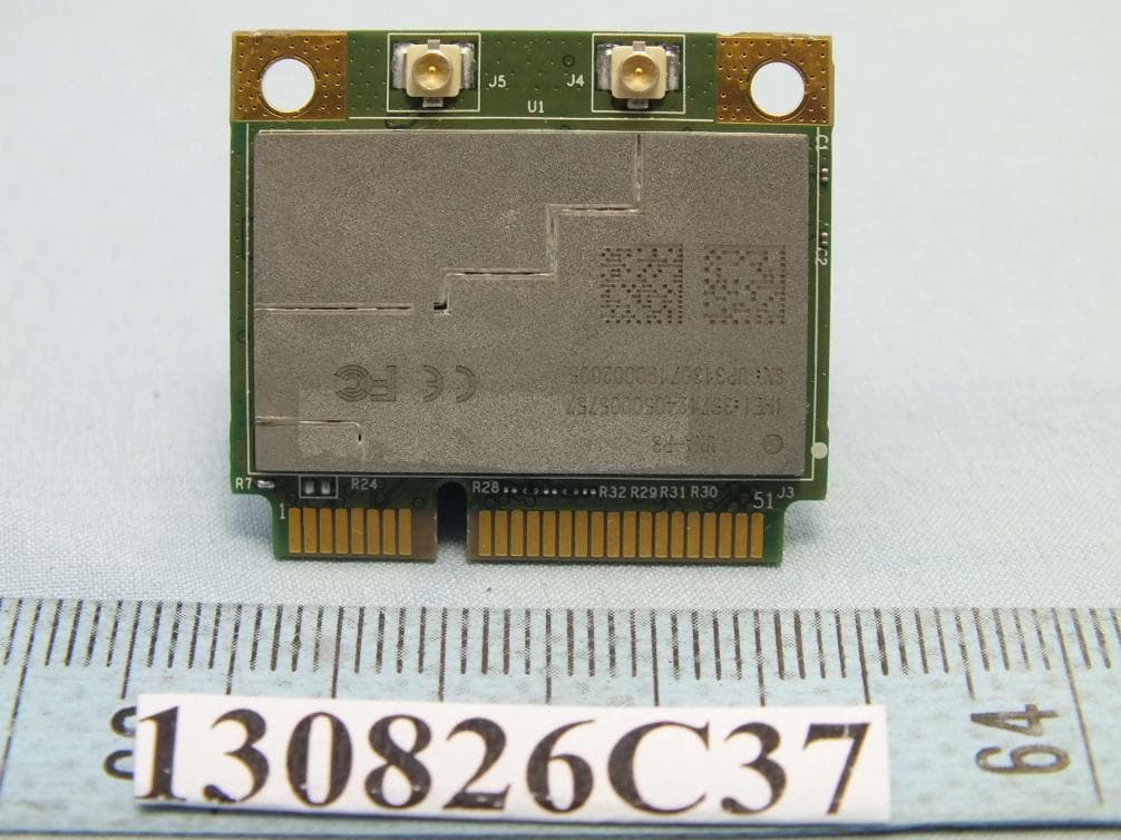
IXM-UNA-P3
Nov 21, 20133G Module
Equipment Class
PCB - PCS Licensed Transmitter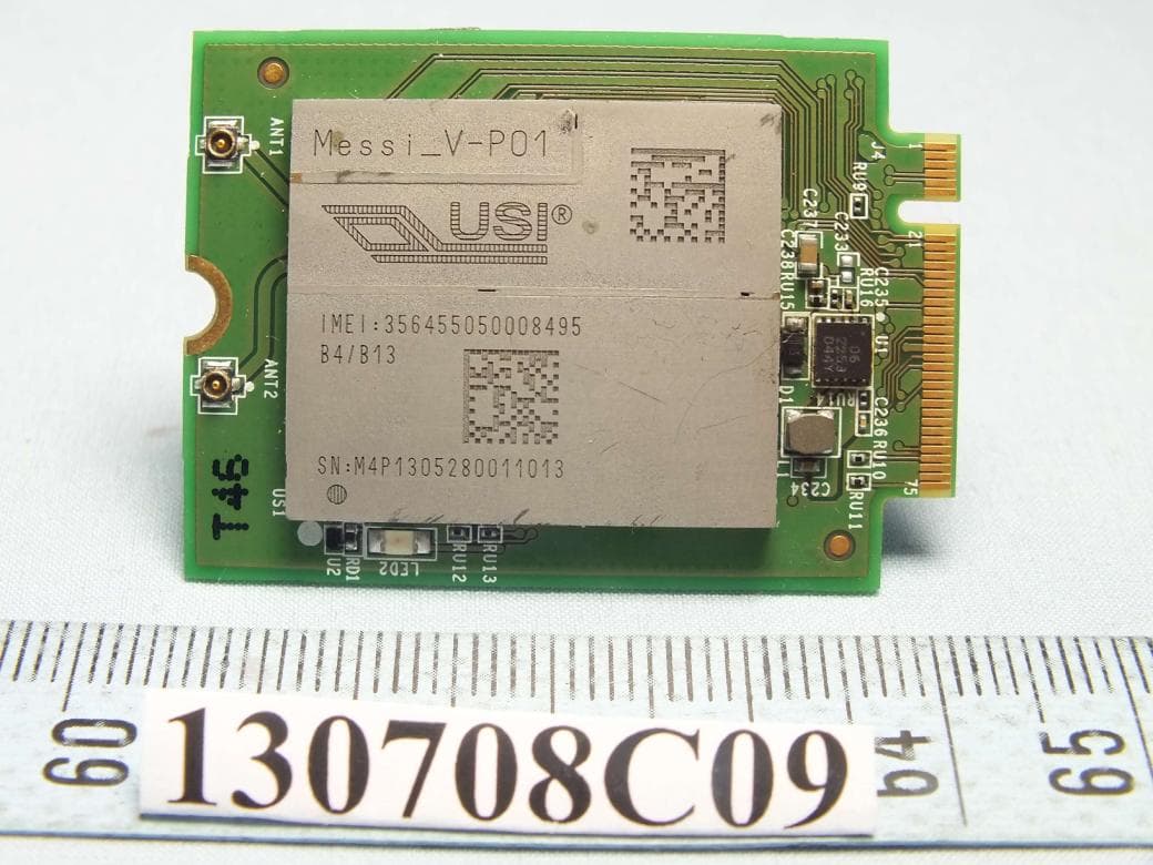
IXMMESSI-V
Sep 29, 2013LTE Module
Equipment Class
JBP - Part 15 Class B Computing Device Peripheral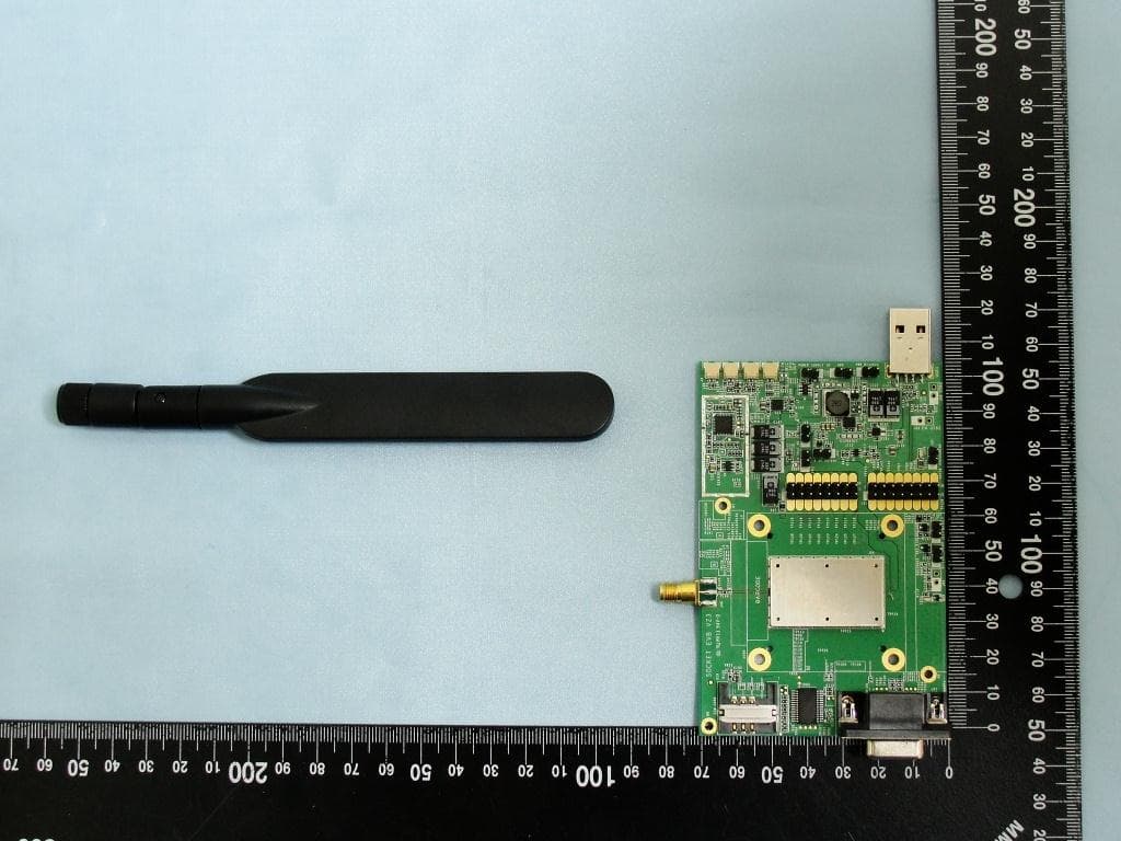
IXM-UNA850
Oct 01, 2012UNA 850 module
Equipment Class
PCB - PCS Licensed Transmitter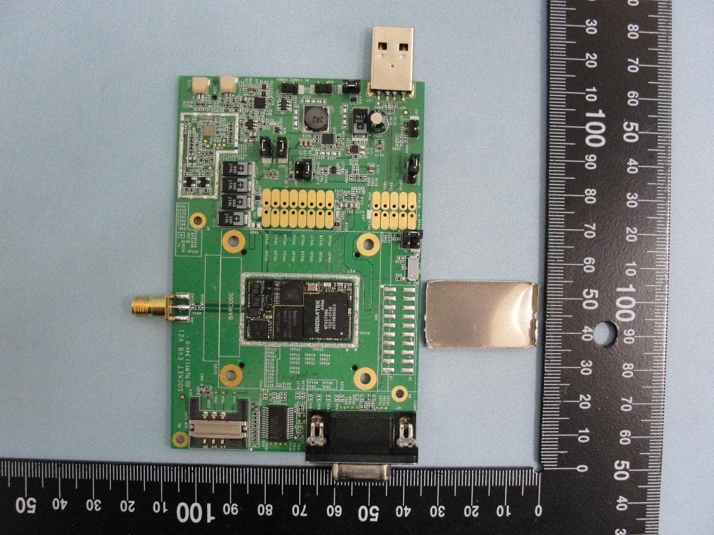
IXM-UNA900
Apr 19, 2012WWAN Module
Equipment Class
PCB - PCS Licensed Transmitter
IXMUGNAS-P3
Jul 28, 2011NETWORK ATTACHED STORAGE
Equipment Class
DTS - Digital Transmission System