IXMMESSI-VLTE Module
Universal Scientific Industrial Co., Ltd.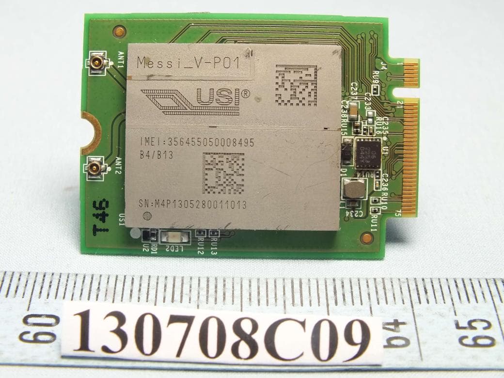
Click to zoom
Application Details
- Equipment Class
- JBP - Part 15 Class B Computing Device Peripheral
- Date of Grant
- Sep 29, 2013
- Application Purpose
- Original Equipment
- Date of Application
- Sep 29, 2013
- Equipment Note
- LTE Module
- Country
- Taiwan
Documents & Files
Document Text
Text extracted from the exhibit documents filed with the FCC. Open a document above to read the original.
Users Manual
1/13 Rev1.2 MESSI-V M2 I/O APPLICATION 4G LTE Module (NGFF type) Doc. Title MESSI-V M2 I/O APPLICATION Originator David Tsui Concurrence Achau Lee Approved by Version Date 2013/08/08 2/13 Rev1.2 Revision History Rev Draft/Changes Date 1.0 First version released (DVT phase) 2013/01/10 3/13 Rev1.2 Introduction: MESSI-V M2 is an advanced and compact NGFF board / module which supports LTE category 3 (CAT-3) throughputs. MESSI-V M2 supports for UART, USB2.0, USIM and antenna interface. The details of I/O interfaces are described in the sections as followings: UART Interface USB2.0 Interface USIM Interface Power Input JTAG & Reset GPIO Antenna Interface Others 4/13 Rev1.2 1. UART Interface MESSI-V M2 board supports one UART port for debugging and downloading. The baud rate speed is up to 115200bps. Signal level is 3.3V. If MESSI-V M2 module goes through standard RS-232 interface to connect with PC, It is recommended to use TI TRS3253EIRSMR for best baud rate to catch log file and download boot loader setting. Pin NO. Pin name Description 62 UART_RX UART receive input 64 UART_TX UART transmit output Figure1-1: UART block diagram. Figure1-2: RS-232 connection 5/13 Rev1.2 2. USB 2.0 Interface The USB interface is compliant with Version 2.0 of the USB standard for high speed operation. The reference circuit is showing in Figure2-1as following. Pin NO. Pin name Description 7 USB_D+ Universal Serial BUS 9 USB_D- Figure2-1: USB connection 6/13 Rev1.2 3. USIM interface The USIM pins provide the connections necessary to interface to a USIM socket located on the host device. Voltage levels over this interface comply with 3GPP standards. MSEEI module outputs a SIMPWR power rail 1.8V and 3V. Pin NO. Pin name Description 36 SIMPWR 1.8V/3V output to SIM card. 34 SIMIO SIM data IO 32 SIMCLK SIM clock 30 SIMRST SIM reset The reference circuit is showing in Figure3-1as following. Figure3-1: USIM card connection 7/13 Rev1.2 4. Power Input MESSI-V M2 power input pin is VBAT. The power input range is from 3.4V to 5V with USB, external power or Battery. Figure 4-1 shows external power source to MESSI module. Pin NO. Pin name Description 2 3.3V Power input 4 3.3V 70 3.3V 72 3.3V 74 3.3V Figure4-1: External power for MESSI-V M2 board. 8/13 Rev1.2 5. JTAG & Reset Emulation JTAG is used to debug and run SW on embedded MIPS processors. MESSI has a single Reset input (RSTN). This signal should be connected and driven by the power management unit or the host application processor, depending on the usage scenario. Pin NO. Pin name Description 42 TCK Clock 43 TMS Test Mode 47 TDI Input Data 49 TDO Output Data 53 EJTAG_TRST EJTAG Reset 67 TRST MESSI Reset Input(1.8V) Figure 6-1: JTAG connection 9/13 Rev1.2 6. GPIOs MESSI-V M2 has various software-controlled general purpose IO (GPIO) pins which are listed below. The user can use these GPIOs for any general purpose their design calls for. If the GPIO is not in use, it is recommended to leave the pin as floating. Pin NO. Pin name Description 8 GPIO4 3.3V General Purpose I/O 35 GPIO20 1.8V General Purpose I/O 31 GPIO19 1.8V General Purpose I/O 29 GPIO18 1.8V General Purpose I/O 20 GPIO11 1.8V General Purpose I/O 22 GPIO10 1.8V General Purpose I/O 24 GPIO9 1.8V General Purpose I/O 26 GPIO8 1.8V General Purpose I/O 28 GPIO12 1.8V General Purpose I/O 40 GPIO13 1.8V General Purpose I/O 42 GPIO14 1.8V General Purpose I/O 44 GPIO15 1.8V General Purpose I/O 46 GPIO16 1.8V General Purpose I/O 10/13 Rev1.2 7. Antenna Interface MESSI-V M2 support MIMO antenna. The reference RF cable SPEC is down below. Pin NO. Pin name Description ANT 1 RXTX RF Transmission and RF receive chain ANT 2 RXONLY RF receive chain Figure 8-1: MIMO antenna connection 11/13 Rev1.2 8. Others The following Pins are reserved for future update. The user can leave these pin as floating. Pin NO. Pin name Description 23 PMU SLEEP/PWR_REQ Reserved 66 SCR_DTCT Reserved 9. Mechanical Outline Figure9-1: Messi-V M2 Mechanical 12/13 Rev1.2 Federal Communication Commission Interference Statement This device complies with Part 15 of the FCC Rules. Operation is subject to the following two conditions: (1) This device may not cause harmful interference, and (2) this device must accept any interference received, including interference that may cause undesired operation. This equipment has been tested and found to comply with the limits for a Class B digital device, pursuant to Part 15 of the FCC Rules. These limits are designed to provide reasonable protection against harmful interference in a residential installation. This equipment generates, uses and can radiate radio frequency energy and, if not installed and used in accordance with the instructions, may cause harmful interference to radio communications. However, there is no guarantee that interference will not occur in a particular installation. If this equipment does cause harmful interference to radio or television reception, which can be determined by turning the equipment off and on, the user is encouraged to try to correct the interference by one of the following measures: - Reorient or relocate the receiving antenna. - Increase the separation between the equipment and receiver. - Connect the equipment into an outlet on a circuit different from that to which the receiver is connected. - Consult the dealer or an experienced radio/TV technician for help. FCC Caution: Any changes or modifications not expressly approved by the party responsible for compliance could void the user's authority to operate this equipment. This transmitter must not be co-located or operating in conjunction with any other antenna or transmitter. 13/13 Rev1.2 Radiation Exposure Statement: This equipment complies with FCC radiation exposure limits set forth for an uncontrolled environment. This equipment should be installed and operated with minimum distance 20cm between the radiator & your body. This device is intended only for OEM integrators under the following conditions: 1) The …
Text truncated - open the document above for the full version.
Cover Letter(s)
141Lan35LTaipingRoSec.10TuenNan-TouTaiwan Date:August132013 FederalCommunicationsCommission 7345OaklandMillsRoad ColumbiaMD21046 SUbject:RequestforConfidentiality FCCID: ToWhomMayConcern PursuanttotheprovisionsofSections0 57d0 59ofCommission'srules(47CFR§§0570 59) wearerequestingtheCommissiontowithholdthefollowingattachmentsasconfidentialdocumentfrom publicdisclosureindefinitely. SchematicDiagram BlockDiagram Partsst Tune-upProcedure OperationalDescription Abovementioneddocumentcontainsdetailedsystemandequipmentdescriptionareconsideredas proprietaryinformationinoperationoftheequipmenThepublicdisclosureofabovedocumentsmight beharmfultoourcompanyandwouldgivecompetitoranunfairadvantageinthemarke InadditionaltoabovementioneddocumentspursuanttoPublicNoticeDA04-1705oftheCommission' s policyinordertocomplywiththemarketingregulationsin47CFT§2.803andtheimportationrulesin 47CFR§2204whileensuringthatbusinesssensitiveinformationremainsconfidentialuntiltheactual marketingofnewlyauthorizeddevices.Wearerequestingthecommissiontograntshort-term confidentialityrequestonthefollowingattachmentsuntil180daysaftertheGrantDateofEquipment Authorizations. ExternalPhotos InternalPhotos TestSetupPhotos Usersfanual isourunderstandingthatallmeasurementtestreportsFCCIDlabelformatandcorrespondentduring certificationreviewprocesscannotbegrantedasconfidentialdocumentsIdthoseinformationwillbe availableforpublicreviewoncethegrantofequipmentauthorizationisissued. F BestRegards 0;l1 tV}\A
Cover Letter(s)
FCC ID: IXMMESSI-V Modular Approval Request Letter Bureau Veritas Consumer Products Services (H.K.) Ltd., Taoyuan Branch September 13, 2013 Dear Application Examiner, We, Universal Scientific Industrial Co., Ltd., claim that the EUT, FCC ID: IXMMESSI-V is a LTE module and would like to have your authorization as a modular approval specific to the mobile RF exposure condition. The requirements of section 15.212 of FCC rules have been met and shown on the following statements. 1. “The modular transmitter must have its own RF shielding.” The radio portion of this module has been shielded, please see exhibition External Photo. 2. “The modular transmitter must have buffered modulation/data inputs.” The EUT has buffered data input, it is integrated in chip ALT3100-B2 and TPS659122YFFR. 3. “The modular transmitter must have its own power supply regulation.” The part number of this regulator is TPS659122YFFR. 4. “The modular transmitter must comply with the antenna requirements of section 15.203 and 15.204(C).” The EUT meets the FCC antenna requirements. The spurious emission, unique antenna connector and photo of antennas are shown in the test report. 5. “The modular transmitter must be tested in a stand-alone configuration” The EUT was tested in a stand-alone configuration via a USB extender. Please see section Photographs of Test Configuration in the test report, the EUT was plugged in this extender. 6. “The modular transmitter must be labeled with its own FCC ID number.” Please see exhibition Label Sample for the FCC ID of this module. And also in the exhibition Users Manual, there are instructions give to the OEM on how to label the end product. FCC ID: IXMMESSI-V 7. “The modular transmitter must comply with any specific rule or operating requirements applicable to the transmitter and the manufacturer must provide adequate instructions along with the module to explain any such requirements.” The EUT is compliant with all applicable FCC rules. Detail instructions for maintaining compliance are given in the Users Manual. 8. “The modular transmitter must comply with any applicable RF exposure requirements.” The EUT is compliant with all applicable RF exposure requirements. RF Exposure is addressed in the RF exposure exhibition. Please contact me if you have any further question. Thanks for your attention. Best Regards, ____________________________ Daniel Lee Vice President Bureau Veritas Consumer Products Services (H.K.) Ltd., Taoyuan Branch
Cover Letter(s)
141Lane351TaipingRoadSec.1TsaoTuenNan-TauTaiwan Date:August132013 Powerof Attornev Towhomit mayconcern PleasebenotifiedthatIhavedignatedDanielLeeof BureauVeritasConsumerProducts ServicesLtd.TaoyuanBranch(BVCPSTaoyuanBranch)of Taiwanas thepersonbeingresponsible forthisprojectandto signtheform731andotherdocumentation. AnyandallactscarriedoutbyDanielLeeofBureauVeritasConsumerProductsServices(HJd. TaoyuanBranch(BVCPSTaoyuanBranch)of Taiwanon themattersrelatingto all processesrequiredin the FCCapprovalandanycommunicationneededwiththenationalauthorityshallhavethesamelegal authorityas actsonourownbehal Asdefinedin 47CFRCh.1.2002(b)wefurthercertifythatneithertheapplicantnoranypartyto this applicationis subjectto a denialto FederalbenefitsincludingFCCbenefitspursuantto section5301of the Anti-DrugAbuseActof 199821U.S.C.835(a). Thisauthorizationis limitedto theproductof as following: FCCID: If youhaveanyacknowledgementandresponsepleasesendit to DanielLeeof BureauVeritasConsumer ProductsServices(H.K.)d. TaoyuanBranch(BVCPSTaoyuanBranch)of Taiwandirectly. Shouldyouhaveanyquestionor commentregardingthismatterpleasehavemybestattention. Sincerelyyours F ~d1
Cover Letter(s)
SCS-F18: Project and Product Certification Representative Authorization Letter Page 1 of 2 Rev 3.0 775 Montague Expressway Milpitas, CA 95035 Tel: 408-526-1188 Fax: 408-526-1088 Email: [email protected] Project and Product Certification Representative Authorization Letter Reason for Amendment (current / obsolete) Revision History Approved Date From To Initial Release (obsolete) 1.0 1.0 Nov-14-2006 Revised wording (obsolete) 1.0 2.0 Sept–25-2007 Updated company template (current) 2.0 3.0 Jan-31-2012 SCS-F18: Project and Product Certification Representative Authorization Letter Page 2 of 2 Rev 3.0 September 17, 2013 To: SIEMIC, INC. 775 Montague Expressway, Milpitas, CA 95035 USA Dear Sir/Madam, Re: Project and Product Certification Representative Authorization Letter We, Universal Scientific Industrial Co., Ltd. hereby authorize SIEMIC, INC. to act as a Certification Body for certifying for the following project(s): LTE Module / IXMMESSI-V We affirm that between SIEMIC and Universal Scientific Industrial Co., Ltd., any difference in understanding, including test plan, measurement methods, applicable standards and relevant procedures and processes have been resolved prior to commencement of testing activities. Sincerely, _____________________ Daniel Lee / Vice President Bureau Veritas Consumer Products Services (H.K.) Ltd., Taoyuan Branch Tel: +886 3 318 3232 #1857
External Photos
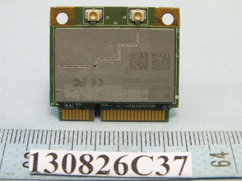
1 CONSTRUCTION PHOTOS OF EUT
Internal Photos
1 CONSTRUCTION PHOTOS OF EUT
Test Report
Report No.: FC130527C07B 1 of 21 Report Format Version 5.0.0 Reference No.: 130708C09 FCC CERTIFICATION TEST REPORT REPORT NO.: FC130527C07B MODEL NO.: Messi-V RECEIVED: Jul. 08, 2013 TESTED: Jul. 10, 2013 ~ Jul. 15, 2013 ISSUED: Jul. 22, 2013 APPLICANT: Universal Scientific Industrial Co., Ltd. ADDRESS: 141, Lane 351, Taiping Road, Sec. 1, Tsao Tuen, Nan-Tou, Taiwan ISSUED BY: Bureau Veritas Consumer Products Services (H.K.) Ltd., Taoyuan Branch LAB ADDRESS: No. 19, Hwa Ya 2nd Rd., Wen Hwa Tsuen, Kwei Shan Hsiang, Taoyuan Hsien 333, Taiwan This report is for your exclusive use. Any copying or replication of this report to or for any other person or entity, or use of our name or trademark, is permitted only with our prior written permission. This report sets forth our findings solely with respect to the test samples identified herein. The results set forth in this report are not indicative or representative of the quality or characteristics of the lot from which a test sample was taken or any similar or identical product unless specifically and expressly noted. Our report includes all of the tests requested by you and the results thereof based upon the information that you provided to us. You have 60 days from date of issuance of this report to notify us of any material error or omission caused by our negligence, provided, however, that such notice shall be in writing and shall specifically address the issue you wish to raise. A failure to raise such issue within the prescribed time shall constitute your unqualified acceptance of the completeness of this report, the tests conducted and the correctness of the report contents. Unless specific mention, the uncertainty of measurement has been explicitly taken into account to declare the compliance or non-compliance to the specification This report should not be used by the client to claim product certification, approval, or endorsement by TAF, NVLAP, NIST or any government agencies. Report No.: FC130527C07B 2 of 21 Report Format Version 5.0.0 Reference No.: 130708C09 Table of Contents RELEASE CONTROL RECORD ................................................................................. 3 1 CERTIFICATION ............................................................................................ 4 2 SUMMARY OF TEST RESULTS ................................................................... 5 2.1 MEASUREMENT UNCERTAINTY ................................................................. 5 3 GENERAL INFORMATION ............................................................................ 6 3.1 GENERAL DESCRIPTION OF EUT .............................................................. 6 3.2 DESCRIPTION OF TEST MODES ................................................................ 6 3.3 DESCRIPTION OF SUPPORT UNITS .......................................................... 7 3.4 CONFIGURATION OF SYSTEM UNDER TEST ............................................ 7 4 TEST TYPES AND RESULTS ....................................................................... 8 4.1 RADIATED EMISSION MEASUREMENT ...................................................... 8 4.1.1 LIMITS OF RADIATED EMISSION MEASUREMENT ................................... 8 4.1.2 TEST INSTRUMENTS ................................................................................... 9 4.1.3 TEST PROCEDURES ................................................................................. 11 4.1.4 DEVIATION FROM TEST STANDARD ........................................................ 12 4.1.5 TEST SETUP ............................................................................................... 13 4.1.6 EUT OPERATING CONDITIONS ................................................................ 13 4.1.7 TEST RESULTS .......................................................................................... 14 5 PHOTOGRAPHS OF THE TEST CONFIGURATION .................................. 18 6 INFORMATION ON THE TESTING LABORATORIES ................................. 20 7 APPENDIX A – MODIFICATION RECORDERS FOR ENGINEERING CHANGES TO THE EUT BY THE LAB ........................................................ 21 Report No.: FC130527C07B 3 of 21 Report Format Version 5.0.0 Reference No.: 130708C09 RELEASE CONTROL RECORD ISSUE NO. REASON FOR CHANGE DATE ISSUED FC130527C07B Original release. Jul. 22, 2013 Report No.: FC130527C07B 4 of 21 Report Format Version 5.0.0 Reference No.: 130708C09 1 CERTIFICATION PRODUCT: LTE Module BRAND: Universal Global Scientific Industrial Co., Ltd. MODEL NO.: Messi-V APPLICANT: Universal Scientific Industrial Co., Ltd. TESTED: Jul. 10, 2013 ~ Jul. 15, 2013 TEST SAMPLE: Production Unit STANDARD: FCC Part 15, Subpart B, Class B ANSI C63.4:2009 The above equipment (Model: Messi-V) has been tested by Bureau Veritas Consumer Products Services (H.K.) Ltd., Taoyuan Branch, and found compliance with the requirement of the above standards. The test record, data evaluation & Equipment Under Test (EUT) configurations represented herein are true and accurate accounts of the measurements of the sample’s EMC characteristics under the conditions specified in this report. PREPARED BY : , DATE : Jul. 22, 2013 Vera Huang / Specialist APPROVED BY : , DATE : Jul. 22, 2013 Derrick Dai / Assistant Manager Report No.: FC130527C07B 5 of 21 Report Format Version 5.0.0 Reference No.: 130708C09 2 SUMMARY OF TEST RESULTS The EUT has been tested according to the following specifications. EMISSION Standard Test Type Result Remarks FCC Part 15, Subpart B, Class B Radiated emission test (30MHz~40GHz) PASS Meet the requirement of limit. Minimum passing margin is -8.98dB at 920.30MHz. 2.1 MEASUREMENT UNCERTAINTY Where relevant, the following measurement uncertainty levels have been estimated for tests performed on the EUT as specified in CISPR 16-4-2: This uncertainty represents an expanded uncertainty expressed at approximately the 95% confidence level using a coverage factor of k=2. Measurement Frequency Uncertaint…
Text truncated - open the document above for the full version.
Test Setup Photos
Report No.: FC130527C07B 18 of 21 Report Format Version 5.0.0 Reference No.: 130708C09 5 PHOTOGRAPHS OF THE TEST CONFIGURATION Radiated Emission Test (30MHz~1GHz) Report No.: FC130527C07B 19 of 21 Report Format Version 5.0.0 Reference No.: 130708C09 Radiated Emission Test (Above 1GHz)
Contact Information
Applicant
Martin Shih(Section Manager)
Test Firm
Bureau Veritas CPS (H.K.) Ltd., Taoyuan BranchRichard Chen
Technical Specifications
| # | Rule Parts | Frequency Range | Power Output |
|---|---|---|---|
| 1 | 15B | - | - |
Other Applications from Universal Scientific Industrial Co., Ltd.
IXM-UNA-P3
Nov 21, 20133G Module
Equipment Class
PCB - PCS Licensed Transmitter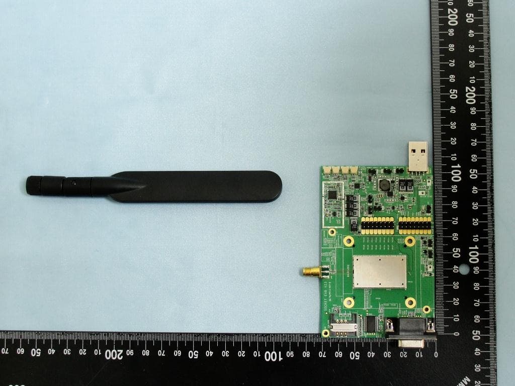
IXM-UNA850
Oct 01, 2012UNA 850 module
Equipment Class
PCB - PCS Licensed Transmitter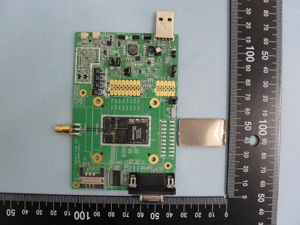
IXM-UNA900
Apr 19, 2012WWAN Module
Equipment Class
PCB - PCS Licensed Transmitter
IXMUGNAS-P3
Jul 28, 2011NETWORK ATTACHED STORAGE
Equipment Class
DTS - Digital Transmission System
IXMBMGPCS08A
Oct 30, 2007BLUETOOTH 2.0+EDR USB MODULE
Equipment Class
DSS - Part 15 Spread Spectrum Transmitter