IXM-RTGBR02WIRLESS ROUTER
Universal Scientific Industrial Co., Ltd.
Click to zoom
Application Details
- Equipment Class
- DTS - Digital Transmission System
- Date of Grant
- Dec 23, 2004
- Application Purpose
- Original Equipment
- Date of Application
- Dec 23, 2004
- Equipment Note
- WIRLESS ROUTER
- Frequency Range
- 2412.00000000 - 2462.00000000
- Country
- Taiwan
Documents & Files
Document Text
Text extracted from the exhibit documents filed with the FCC. Open a document above to read the original.
Users Manual
Wireless MAXg Router Install Guide Guide d'installation Installationsanleitung Guida all'installazione rapida Guía breve de instalación Beknopte installatiegids R24.0506.00 Quick Installation Guide ......................................................................... 1 Guide d'installation rapide ..................................................................... 7 Installationsanleitung............................................................................. 13 Guida all'installazione rapida .................................................................19 Guía breve de instalación ....................................................................... 25 Beknopte installatiegids......................................................................... 31 1 Quick Installation Guide Package Contents: Connecting the Wireless MAXg Router Note: For the most updated information, visit: http://www.usr.com/support You can also refer to the User Guide on the U.S. Robotics Installation CD-ROM for more detailed information. ATTENTION: If you are installing the Wireless MAXg Router and a Wireless MAXg PC Card, PCI Adapter, or USB Adapter at the same time, refer to the Installation Guide for the Wireless MAXg PC Card, PCI Adapter, or USB Adapter for combined installa- tion instructions. Do not perform the installation steps in this guide. Step One: Connect the Wireless MAXg Router I.Turn off your computer and your cable or DSL modem. Disconnect the Ethernet cable from the Network Interface Card (NIC) of your computer, but leave it connected to your cable or DSL modem. II.Connect the Ethernet cable from your cable or DSL modem or network connection to the WAN port of the Wireless MAXg Router. III.Connect an Ethernet cable to the Network Interface Card (NIC) of your computer and to one of the LAN ports of the Wireless MAXg Router. IV.Connect the antenna to the Wireless MAXg Router. V.Connect the power adapter to the Wireless MAXg Router and to a standard wall power out- let. Make sure your computer is turned on. Note to UK Users: Attach the correct power plug to the power adapter. USR5461 Wireless MAXg Router5VDC power supply Quick Installation GuideInstallation CD-ROM which includes User Guide One (1) Ethernet cableDetachable antenna ! 2 Step Two: Configure the Wireless MAXg Router •Launch a Web browser. In the location or address line of your Web browser, type http://192.168.2.1 to access the Web User Interface. The Setup Wizard will be displayed. •Click Start to begin the Setup Wizard procedure. •Follow the on-screen instructions in the Setup Wizard to configure the basic connection set- tings of the Wireless MAXg Router. For more detailed Setup Wizard instructions, refer to the Installation section of the User Guide on the Installation CD-ROM. Note: Refer to the Installation procedure in the User Guide on the Installation CD-ROM for more detailed Setup Wizard information. Contact your ISP if you have any questions about your Internet connection. Step Three: Verify the Internet connection When you are finished configuring the basic connection settings, you should have Internet access. To confirm your connection, launch a Web browser and register your product at www.usr.com/productreg If the page loads, you are finished with the installation procedure. If the page does not load, refer to the Troubleshooting section. Congratulations! The installation procedure is now complete. You should now have shared Internet access. If you experience any difficulties, refer to the Troubleshooting section of this guide or to the User Guide on the Installation CD-ROM for more detailed information. Note: After you have completed the installation and configuration procedures, it is recom- mended that you create a backup file of your settings in case you ever experience some dif- ficulties and want to restore your settings. Perform the following steps: •Launch a Web browser. In the location or address line of your Web browser, type http://192.168.2.1 to access the Web User Interface. •You will be prompted to enter your user name and password. After entering your user name and password, the Web User Interface will open. •Click the Device tab and then click Back Up in the Back Up Settings section. Refer to the User Guide on the Installation CD-ROM for more information about this feature. 3 Troubleshooting The Setup Wizard was unable to detect my Internet connection. Possible Solution: You will need to manually configure your Internet connection. There are two methods of instruc- tions you can follow to setup your Internet connection: If you are still in the Setup Wizard or If you have already closed the Setup Wizard. If you are still in the Setup Wizard: Select your Internet connection type: either Cable, DSL Router, satellite, ISN, LAN, or other or DSL modem (also known as PPPoE). Depending on your selection, you will need to enter some information that was provided by your ISP. After entering all of your necessary informa- tion, click Next. Continue to follow the on-screen instructions to complete the Setup Wizard. For more information about the settings, refer to the Web User Interface section of the User Guide on the Installation CD-ROM. If you have already closed the Setup Wizard: Launch a Web browser. In the location or address line of your Web browser, type http://192.168.2.1 to access the Web User Interface. Click the Internet tab. Select your Inter- net connection type: either Cable, DSL Router, satellite, ISN, LAN, or other or DSL modem (also known as PPPoE). Depending on your selection, you will need to enter some information that was provided by your ISP. When you are finished, click Save. You should now be able to access the Internet. For more information about the settings, refer to the Web User Interface section of the User Guide on the Installation CD-ROM. I am no longer able to access the Internet. Possible Solution: Make sure that the power cord and all the Ethernet cables are connected cor…
Text truncated - open the document above for the full version.
External Photos
FCC TEST REPORT REPORT NO. : FR4N2202 SPORTON International Inc. PAGE NUMBER : A1 OF A24 TEL : 886-2-2696-2468 ISSUED DATE : Dec. 21, 2004 FAX : 886-2-2696-2255 APPENDIX A. Photographs of EUT External Router FCC TEST REPORT REPORT NO. : FR4N2202 SPORTON International Inc. PAGE NUMBER : A2 OF A24 TEL : 886-2-2696-2468 ISSUED DATE : Dec. 21, 2004 FAX : 886-2-2696-2255 FCC TEST REPORT REPORT NO. : FR4N2202 SPORTON International Inc. PAGE NUMBER : A3 OF A24 TEL : 886-2-2696-2468 ISSUED DATE : Dec. 21, 2004 FAX : 886-2-2696-2255 FCC TEST REPORT REPORT NO. : FR4N2202 SPORTON International Inc. PAGE NUMBER : A4 OF A24 TEL : 886-2-2696-2468 ISSUED DATE : Dec. 21, 2004 FAX : 886-2-2696-2255 FCC TEST REPORT REPORT NO. : FR4N2202 SPORTON International Inc. PAGE NUMBER : A5 OF A24 TEL : 886-2-2696-2468 ISSUED DATE : Dec. 21, 2004 FAX : 886-2-2696-2255 FCC TEST REPORT REPORT NO. : FR4N2202 SPORTON International Inc. PAGE NUMBER : A6 OF A24 TEL : 886-2-2696-2468 ISSUED DATE : Dec. 21, 2004 FAX : 886-2-2696-2255 FCC TEST REPORT REPORT NO. : FR4N2202 SPORTON International Inc. PAGE NUMBER : A7 OF A24 TEL : 886-2-2696-2468 ISSUED DATE : Dec. 21, 2004 FAX : 886-2-2696-2255 FCC TEST REPORT REPORT NO. : FR4N2202 SPORTON International Inc. PAGE NUMBER : A8 OF A24 TEL : 886-2-2696-2468 ISSUED DATE : Dec. 21, 2004 FAX : 886-2-2696-2255 FCC TEST REPORT REPORT NO. : FR4N2202 SPORTON International Inc. PAGE NUMBER : A9 OF A24 TEL : 886-2-2696-2468 ISSUED DATE : Dec. 21, 2004 FAX : 886-2-2696-2255 FCC TEST REPORT REPORT NO. : FR4N2202 SPORTON International Inc. PAGE NUMBER : A10 OF A24 TEL : 886-2-2696-2468 ISSUED DATE : Dec. 21, 2004 FAX : 886-2-2696-2255 FCC TEST REPORT REPORT NO. : FR4N2202 SPORTON International Inc. PAGE NUMBER : A11 OF A24 TEL : 886-2-2696-2468 ISSUED DATE : Dec. 21, 2004 FAX : 886-2-2696-2255 FCC TEST REPORT REPORT NO. : FR4N2202 SPORTON International Inc. PAGE NUMBER : A12 OF A24 TEL : 886-2-2696-2468 ISSUED DATE : Dec. 21, 2004 FAX : 886-2-2696-2255 Access Point FCC TEST REPORT REPORT NO. : FR4N2202 SPORTON International Inc. PAGE NUMBER : A13 OF A24 TEL : 886-2-2696-2468 ISSUED DATE : Dec. 21, 2004 FAX : 886-2-2696-2255 FCC TEST REPORT REPORT NO. : FR4N2202 SPORTON International Inc. PAGE NUMBER : A14 OF A24 TEL : 886-2-2696-2468 ISSUED DATE : Dec. 21, 2004 FAX : 886-2-2696-2255 FCC TEST REPORT REPORT NO. : FR4N2202 SPORTON International Inc. PAGE NUMBER : A15 OF A24 TEL : 886-2-2696-2468 ISSUED DATE : Dec. 21, 2004 FAX : 886-2-2696-2255 FCC TEST REPORT REPORT NO. : FR4N2202 SPORTON International Inc. PAGE NUMBER : A16 OF A24 TEL : 886-2-2696-2468 ISSUED DATE : Dec. 21, 2004 FAX : 886-2-2696-2255 FCC TEST REPORT REPORT NO. : FR4N2202 SPORTON International Inc. PAGE NUMBER : A17 OF A24 TEL : 886-2-2696-2468 ISSUED DATE : Dec. 21, 2004 FAX : 886-2-2696-2255 FCC TEST REPORT REPORT NO. : FR4N2202 SPORTON International Inc. PAGE NUMBER : A18 OF A24 TEL : 886-2-2696-2468 ISSUED DATE : Dec. 21, 2004 FAX : 886-2-2696-2255 FCC TEST REPORT REPORT NO. : FR4N2202 SPORTON International Inc. PAGE NUMBER : A19 OF A24 TEL : 886-2-2696-2468 ISSUED DATE : Dec. 21, 2004 FAX : 886-2-2696-2255 Antenna FCC TEST REPORT REPORT NO. : FR4N2202 SPORTON International Inc. PAGE NUMBER : A20 OF A24 TEL : 886-2-2696-2468 ISSUED DATE : Dec. 21, 2004 FAX : 886-2-2696-2255 FCC TEST REPORT REPORT NO. : FR4N2202 SPORTON International Inc. PAGE NUMBER : A21 OF A24 TEL : 886-2-2696-2468 ISSUED DATE : Dec. 21, 2004 FAX : 886-2-2696-2255 FCC TEST REPORT REPORT NO. : FR4N2202 SPORTON International Inc. PAGE NUMBER : A22 OF A24 TEL : 886-2-2696-2468 ISSUED DATE : Dec. 21, 2004 FAX : 886-2-2696-2255 FCC TEST REPORT REPORT NO. : FR4N2202 SPORTON International Inc. PAGE NUMBER : A23 OF A24 TEL : 886-2-2696-2468 ISSUED DATE : Dec. 21, 2004 FAX : 886-2-2696-2255 FCC TEST REPORT REPORT NO. : FR4N2202 SPORTON International Inc. PAGE NUMBER : A24 OF A24 TEL : 886-2-2696-2468 ISSUED DATE : Dec. 21, 2004 FAX : 886-2-2696-2255
ID Label/Location Info
Label Sample:
Internal Photos
FCC TEST REPORT REPORT NO. : FR4N2202 SPORTON International Inc. PAGE NUMBER : B1 OF B13 TEL : 886-2-2696-2468 ISSUED DATE : Dec. 21, 2004 FAX : 886-2-2696-2255 APPENDIX B. Photographs of EUT Internal Router FCC TEST REPORT REPORT NO. : FR4N2202 SPORTON International Inc. PAGE NUMBER : B2 OF B13 TEL : 886-2-2696-2468 ISSUED DATE : Dec. 21, 2004 FAX : 886-2-2696-2255 FCC TEST REPORT REPORT NO. : FR4N2202 SPORTON International Inc. PAGE NUMBER : B3 OF B13 TEL : 886-2-2696-2468 ISSUED DATE : Dec. 21, 2004 FAX : 886-2-2696-2255 FCC TEST REPORT REPORT NO. : FR4N2202 SPORTON International Inc. PAGE NUMBER : B4 OF B13 TEL : 886-2-2696-2468 ISSUED DATE : Dec. 21, 2004 FAX : 886-2-2696-2255 FCC TEST REPORT REPORT NO. : FR4N2202 SPORTON International Inc. PAGE NUMBER : B5 OF B13 TEL : 886-2-2696-2468 ISSUED DATE : Dec. 21, 2004 FAX : 886-2-2696-2255 FCC TEST REPORT REPORT NO. : FR4N2202 SPORTON International Inc. PAGE NUMBER : B6 OF B13 TEL : 886-2-2696-2468 ISSUED DATE : Dec. 21, 2004 FAX : 886-2-2696-2255 FCC TEST REPORT REPORT NO. : FR4N2202 SPORTON International Inc. PAGE NUMBER : B7 OF B13 TEL : 886-2-2696-2468 ISSUED DATE : Dec. 21, 2004 FAX : 886-2-2696-2255 Access Point FCC TEST REPORT REPORT NO. : FR4N2202 SPORTON International Inc. PAGE NUMBER : B8 OF B13 TEL : 886-2-2696-2468 ISSUED DATE : Dec. 21, 2004 FAX : 886-2-2696-2255 FCC TEST REPORT REPORT NO. : FR4N2202 SPORTON International Inc. PAGE NUMBER : B9 OF B13 TEL : 886-2-2696-2468 ISSUED DATE : Dec. 21, 2004 FAX : 886-2-2696-2255 FCC TEST REPORT REPORT NO. : FR4N2202 SPORTON International Inc. PAGE NUMBER : B10 OF B13 TEL : 886-2-2696-2468 ISSUED DATE : Dec. 21, 2004 FAX : 886-2-2696-2255 FCC TEST REPORT REPORT NO. : FR4N2202 SPORTON International Inc. PAGE NUMBER : B11 OF B13 TEL : 886-2-2696-2468 ISSUED DATE : Dec. 21, 2004 FAX : 886-2-2696-2255 FCC TEST REPORT REPORT NO. : FR4N2202 SPORTON International Inc. PAGE NUMBER : B12 OF B13 TEL : 886-2-2696-2468 ISSUED DATE : Dec. 21, 2004 FAX : 886-2-2696-2255 FCC TEST REPORT REPORT NO. : FR4N2202 SPORTON International Inc. PAGE NUMBER : B13 OF B13 TEL : 886-2-2696-2468 ISSUED DATE : Dec. 21, 2004 FAX : 886-2-2696-2255
RF Exposure Info
Document No.:4N2202 RF Exposure Test Report Date: Dec. 21, 2004 FCC ID: IXM-RTGBR02 Sporton International Inc. IXM-APGBR02 This report man not be reproduced, expect in full, without the prior written consent of Sporton International Inc. RF Exposure Test Report for Universal Scientific Industrial Co., Ltd. USR5461 (Router) / USR5451 (Access Point) Equipment : U.S. Robotics Wireless Maxg Router U.S. Robotics Wireless Maxg Access Point Trade Name : USR Model No. : USR5461 (for Router) USR5451 (for Access Point) FCC ID : IXM-RTGBR02 (for Router) IXM-APGBR03 (for Access Point) Filing Type : Certification Applicant : Universal Scientific Industrial Co., Ltd. 141, Lane 351, Taiping Road, Sec. 1, Tsao Tuen , Nan-Tou, Taiwan Without written approval of SPORTON International Inc., the test report shall not be reproduced except in full. SPORTON International Inc. 6F, No.106, Sec. 1, Hsin Tai Wu Rd., Hsi Chih, Taipei Hsien, Taiwan, R.O.C. Document No.: 4N2202 RF Exposure Test Report Date: Dec. 21, 2004 FCC ID: IXM-RTGBR02 Sporton International Inc. IXM-APGBR02 Maximum Permissible Exposure Test Report for USR5461 (Router) / USR5451 (Access Point) 1.0 Introduction The report has been prepared on behalf of Universal Scientific Industrial Co., Ltd. U.S. Robotics Wireless Maxg Router / Access Point to show compliance with the RF Exposure. 1.1 Requirements Three different categories of transmitters are defined by the FCC in OET Bulletin 65. There categories are fixed installation, mobile and portable and are defined as follows: Fixed installation: fixed location means that the device, including its antenna, is physically secured at a permanent location and is not able to be easily moved to another location. Additionally, distance to humans form the antenna is maintained to at least 2 meters. Mobile Devices: a mobile device is defined as a transmitting device designed to be used in other than fixed locations and to be generally used in such a way that a separation distance of at least 20 centimeters is normally maintained between the transmitter’s radiating structures and the body of the user or nearby persons. Transmitters designed to be used by consumers or workers that can be easily re-located are considered mobile devices if they meet the 20 centimeter separation requirement. The FCC rules for evaluating mobile devices for RF compliance are found in 47 CFR 2.1091. Portable Devices: a portable device is defined as a transmitting device designed to be used so that the radiating structure(s) of the device is/are within 20 centimeters of the body of the user. Portable device requirements are found in Section 2.1093 of the FCC’s Rules (47 CFR 2.1093) For this test report the Universal Scientific Industrial Co., Ltd. USR5461 / USR5451are being done as a mobile device and the MPE is evaluated at the 20cm test distance. The FCC also categorizes the use of the device as based upon the user’s awareness and ability to exercise control over his or her exposure. The two categories defined are Occupational/Controlled Document No.: 4N2202 RF Exposure Test Report Date: Dec. 21, 2004 FCC ID: IXM-RTGBR02 Sporton International Inc. IXM-APGBR02 Exposure and General Population/Uncontrolled Exposure. These two categories are defined as follows: Occupational/controlled Exposure: In general, occupational/controlled exposure limits are applicable to situation in which persons are exposed as a consequence of their employment, who have been made fully aware of the potential for exposure. Awareness of the potential for RF exposure in a workplcae or similar environment can be provided through specific training as part of a RF safety program. If appropriate, warning signs and labels can also be used to establish such awareness by providing prominent information on the risk of potential exposure and instructions on methods to minimize such exposure risks. General Population/Uncontrolled Exposure: The general population / uncontrolled exposure limits are applicable to situations in which the general public may be exposed or in which persons who are exposed as a consequence of their employment may not be made fully aware of the potential for exposure or cannot exercise control over their exposure. Members of the general public would come under this category when exposure is not employment-related; for example, in the case of a wireless transmitter that exposes persons in its vicinity. Warning labels placed on low-power consumer devices such as cellular telephones are not considered sufficient to allow the device to be considered under the occupational/controlled category, and the general population/uncontrolled exposure limits apply to these devices. Since there are no warnings or training associated with this unit and it can be used by anyone, U.S. Robotics Wireless Maxg Router / Access Point is evaluated to the General Population / Uncontrolled Exposure limits. 1.2 Radio Frequency Radiation Exposure Evaluation According to 1.1310 of the FCC rules, the power density limit for General Population/Uncontrolled Exposure is 1mW/cm 2 . As this is a mobile application the MPE shall be calculated at 20cm to show compliance with the power density limit. The following formula was used to calculate the Power Density: Document No.: 4N2202 RF Exposure Test Report Date: Dec. 21, 2004 FCC ID: IXM-RTGBR02 Sporton International Inc. IXM-APGBR02 Where: S = Power Density P = Output Power at Antenna Terminals G = Gain of Transmit Antenna (linear gain) R = Distance from Transmitting Antenna For this device, the calculation is as follows: Because the EUT belongs to General Population/ Uncontrolled Exposure, the limit of power density is 1.0 mW/cm². 802.11b Channel NO. Antenna Gain (dBi) Antenna Gain (numeric) Peak Output Power (dBm) Peak Output Power (mW) Calculated RF Exposure at d=20cm (mW/cm²) Limit (mW/cm ²) Channel 01 5.00 3.16 18.99 79.25 0.0499 1.00 Channel 06 5.00 3.16 19.14 82.04 0.0516 1.00 Channel 11 5.00 3.16 19.57 90.57 0.0570 1.…
Text truncated - open the document above for the full version.
Test Report
SPORTON International Inc. FCC ID : IXM-RTGBR02 / IXM-APGBR02 TEL : 886-2-2696-2468 Page No. : i FAX : 886-2-2696-2255 Issued Date : Dec. 21, 2004 FCC TEST REPORT Report No. : FR4N2202 Table of Contents History of this test report....................................................................................................................................ii 1. General Description of Equipment under Test.............................................................................................1 1.1. Applicant ........................................................................................................................................................................................1 1.2 Manufacturer ..................................................................................................................................................................................1 1.3 Basic Description of Equipment under Test ...................................................................................................................................1 1.4 Feature of Equipment under Test ..................................................................................................................................................2 2 Test Configuration of Equipment under Test ...............................................................................................3 2.1 Test Manner ...................................................................................................................................................................................3 2.2 Test Mode ......................................................................................................................................................................................3 2.3 Connection Diagram of Test System .............................................................................................................................................4 2.4 Ancillary Equipment List.................................................................................................................................................................4 3. RF Utility ...........................................................................................................................................................5 4. General Information of Test............................................................................................................................6 4.1 Test Voltage ...................................................................................................................................................................................6 4.2 Standard for Methods of Measurement..........................................................................................................................................6 4.3 Test in Compliance with .................................................................................................................................................................6 4.4 Frequency Range Investigated ......................................................................................................................................................6 4.5 Test Distance .................................................................................................................................................................................6 5. Test Data and Test Result...............................................................................................................................7 5.1 List of Measurements and Examinations .......................................................................................................................................7 5.2 6dB Bandwidth Measurement ........................................................................................................................................................8 5.3 Power Spectral Density Measurement .........................................................................................................................................16 5.4 Band Edges Measurement...........................................................................................................................................................24 5.5 Peak Output Power Measurement ...............................................................................................................................................31 5.6 Conducted Emission Measurement .............................................................................................................................................33 5.7 Radiated Emission Measurement ................................................................................................................................................40 5.8 Antenna Requirements ................................................................................................................................................................50 6. List of Measuring Equipments Used ...........................................................................................................51 7. Uncertainty Evaluation..................................................................................................................................52 Appendix A. Photographs of EUT External Appendix B. Photographs of EUT Internal Appendix C. Photographs of Setup SPORTON International Inc. FCC ID : IXM-RTGBR02 / IXM-APGBR02 TEL : 886-2-2696-2468 Page No. : ii FAX : 886-2-2696-2255 Issued Date : Dec. 21, 2004 FCC TEST REPORT Report No. : FR4N2202 History of this test report Original Report Issue Date: Dec. 21, 2004 ■ No additional attachment. □ Additional attachment were issued as following record: Attachment No.Issue Date Description SPORTON International Inc. FCC ID : XM-RTGBR02 / IXM-APGBR02 TEL : 886-2-2696-2468 Page No. : 1 of 53 FAX : 886-2-2696-2255 Issued Date : De…
Text truncated - open the document above for the full version.
Test Report
SPORTON International Inc. FCC ID : XM-RTGBR02 / IXM-APGBR02 TEL : 886-2-2696-2468 Page No. : 28 of 53 FAX : 886-2-2696-2255 Issued Date : Dec. 21, 2004 FCC TEST REPORT Report No. : FR4N2202 802.11b Tx CH11 (2462MHz) SPORTON International Inc. FCC ID : XM-RTGBR02 / IXM-APGBR02 TEL : 886-2-2696-2468 Page No. : 29 of 53 FAX : 886-2-2696-2255 Issued Date : Dec. 21, 2004 FCC TEST REPORT Report No. : FR4N2202 802.11g Tx CH01 (2412MHz) SPORTON International Inc. FCC ID : XM-RTGBR02 / IXM-APGBR02 TEL : 886-2-2696-2468 Page No. : 30 of 53 FAX : 886-2-2696-2255 Issued Date : Dec. 21, 2004 FCC TEST REPORT Report No. : FR4N2202 802.11g Tx CH11 (2462MHz) SPORTON International Inc. FCC ID : XM-RTGBR02 / IXM-APGBR02 TEL : 886-2-2696-2468 Page No. : 31 of 53 FAX : 886-2-2696-2255 Issued Date : Dec. 21, 2004 FCC TEST REPORT Report No. : FR4N2202 5.5 Peak Output Power Measurement 5.5.1 Measuring Instruments: As described in chapter 6 of this test report. 5.5.2 Test Procedure: The antenna port(RF output)of the EUT was connected to the input(RF input)of a power meter. The power is equal to the reading level on power meter plus cable loss at the EUT antenna terminal. 5.5.3 Test Setup Layout: EUT Power Meter 5.5.4 Test Result: Application Type : 802.11b Temperature : 24°C Relative Humidity : 47 % Test Enginner : Jay Channel Frequency Measured Output Power Limits (MHz) (dBm) (Watt/dBm ) 01 2412 18.99 1W/30 dBm 06 2437 19.14 1W/30 dBm 11 2462 19.57 1W/30 dBm SPORTON International Inc. FCC ID : XM-RTGBR02 / IXM-APGBR02 TEL : 886-2-2696-2468 Page No. : 32 of 53 FAX : 886-2-2696-2255 Issued Date : Dec. 21, 2004 FCC TEST REPORT Report No. : FR4N2202 Application Type : 802.11g Temperature : 24°C Relative Humidity : 47 % Test Enginner : Jay Channel Frequency Measured Output Power Limits (MHz) (dBm) (Watt/dBm ) 01 2412 17.18 1W/30 dBm 06 2437 17.04 1W/30 dBm 11 2462 17.23 1W/30 dBm SPORTON International Inc. FCC ID : XM-RTGBR02 / IXM-APGBR02 TEL : 886-2-2696-2468 Page No. : 33 of 53 FAX : 886-2-2696-2255 Issued Date : Dec. 21, 2004 FCC TEST REPORT Report No. : FR4N2202 5.6 Conducted Emission Measurement 5.6.1 Measuring Instruments As described in chapter 6 of this test Report. 5.6.2 Test Procedures a. The EUT was placed 0.4 meter from the conducting wall of the shielding room was kept at least 80 centimeters from any other grounded conducting surface. b. Connect EUT to the power port of the line impedance stabilization network (LISN). c. All the support units are connect to the other LISN. d. The LISN provides 50 ohm coupling impedance for the measuring instrument. e. The FCC states that a 50 ohm, 50 microhenry LISN should be used. f. Both sides of AC line were checked for maximum conducted interference. g. The frequency range from 150 kHz to 30 MHz was searched. h. Set the test-receiver system to Peak Detect Function and specified bandwidth with Maximum Hold Mode. SPORTON International Inc. FCC ID : XM-RTGBR02 / IXM-APGBR02 TEL : 886-2-2696-2468 Page No. : 34 of 53 FAX : 886-2-2696-2255 Issued Date : Dec. 21, 2004 FCC TEST REPORT Report No. : FR4N2202 5.6.3 Test Data 5.4.1 Frequency Range of Test : 150kHz to 30 MHz Test Mode : Mode 1 Temperature : 26°C Relative Humidity : 47% ■ The test that passed at minimum margin was marked by the frame in the following table. SPORTON International Inc. FCC ID : XM-RTGBR02 / IXM-APGBR02 TEL : 886-2-2696-2468 Page No. : 35 of 53 FAX : 886-2-2696-2255 Issued Date : Dec. 21, 2004 FCC TEST REPORT Report No. : FR4N2202 Test Engineer : Jay SPORTON International Inc. FCC ID : XM-RTGBR02 / IXM-APGBR02 TEL : 886-2-2696-2468 Page No. : 36 of 53 FAX : 886-2-2696-2255 Issued Date : Dec. 21, 2004 FCC TEST REPORT Report No. : FR4N2202 5.4.2 Frequency Range of Test : 150kHz to 30 MHz Test Mode : Mode 2 Temperature : 26°C Relative Humidity : 47% ■ The test that passed at minimum margin was marked by the frame in the following table. SPORTON International Inc. FCC ID : XM-RTGBR02 / IXM-APGBR02 TEL : 886-2-2696-2468 Page No. : 37 of 53 FAX : 886-2-2696-2255 Issued Date : Dec. 21, 2004 FCC TEST REPORT Report No. : FR4N2202 Test Engineer : Jay SPORTON International Inc. FCC ID : XM-RTGBR02 / IXM-APGBR02 TEL : 886-2-2696-2468 Page No. : 38 of 53 FAX : 886-2-2696-2255 Issued Date : Dec. 21, 2004 FCC TEST REPORT Report No. : FR4N2202 5.4.3 Frequency Range of Test : 150kHz to 30 MHz Test Mode : Mode 3 Temperature : 26°C Relative Humidity : 47% ■ The test that passed at minimum margin was marked by the frame in the following table. SPORTON International Inc. FCC ID : XM-RTGBR02 / IXM-APGBR02 TEL : 886-2-2696-2468 Page No. : 39 of 53 FAX : 886-2-2696-2255 Issued Date : Dec. 21, 2004 FCC TEST REPORT Report No. : FR4N2202 Test Engineer : Jay SPORTON International Inc. FCC ID : XM-RTGBR02 / IXM-APGBR02 TEL : 886-2-2696-2468 Page No. : 40 of 53 FAX : 886-2-2696-2255 Issued Date : Dec. 21, 2004 FCC TEST REPORT Report No. : FR4N2202 5.7 Radiated Emission Measurement 5.7.1 Measuring Instruments As described in chapter 6 of this Report. 5.7.2 Test Procedures 1. The EUT was placed on a rotatable table top 0.8 meter above ground. 2. The EUT was set 3 meters from the interference receiving antenna which was mounted on the top of a variable height antenna tower. 3. The table was rotated 360 degrees to determine the position of the highest radiation. 4. The antenna is a broadband antenna and its height is varied between one meter and four meters above ground to find the maximum value of the field strength for both horizontal polarization and vertical polarization of the antenna. 5. For each suspected emission, the EUT was arranged to its worst case and then tune the antenna tower (from 1 m to 4 m) and turntable (from 0 degree to 360 degrees) to find the maximum reading. 6. Set the test-receiver system to Peak or CISPR quasi-peak Detect Function and specified bandwidth wit…
Text truncated - open the document above for the full version.
Contact Information
Applicant
Martin Shih(Section Manager)
Test Firm
SPORTON International IncKathy Lin
Technical Specifications
| # | Rule Parts | Frequency Range | Power Output |
|---|---|---|---|
| 1 | 15C | 2.41 GHz - 2.46 GHz | 91.00 mW |
Other Applications from Universal Scientific Industrial Co., Ltd.
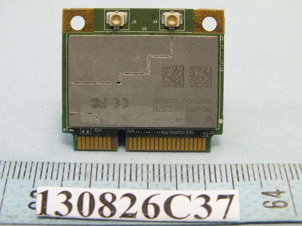
IXM-UNA-P3
Nov 21, 20133G Module
Equipment Class
PCB - PCS Licensed Transmitter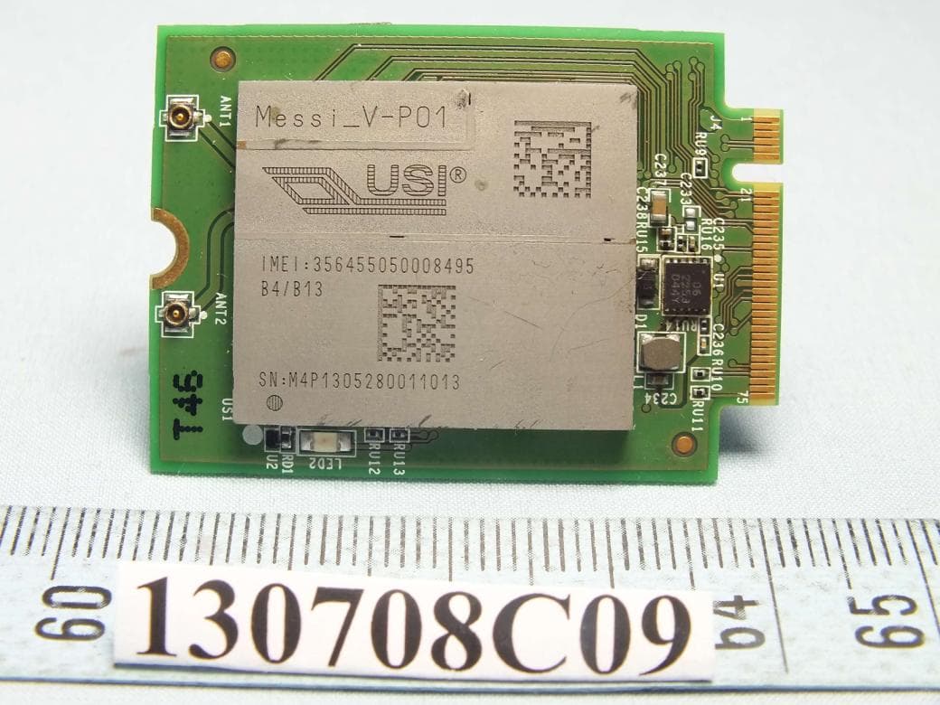
IXMMESSI-V
Sep 29, 2013LTE Module
Equipment Class
JBP - Part 15 Class B Computing Device Peripheral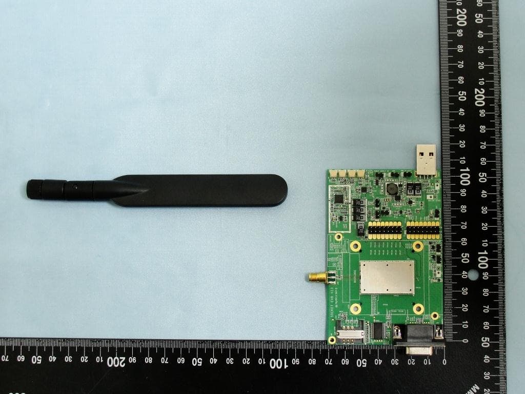
IXM-UNA850
Oct 01, 2012UNA 850 module
Equipment Class
PCB - PCS Licensed Transmitter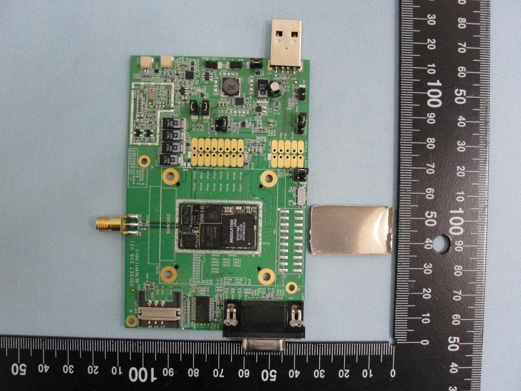
IXM-UNA900
Apr 19, 2012WWAN Module
Equipment Class
PCB - PCS Licensed Transmitter
IXMUGNAS-P3
Jul 28, 2011NETWORK ATTACHED STORAGE
Equipment Class
DTS - Digital Transmission System