IXM-WAK3300Wireless Music Station
Universal Scientific Industrial Co., Ltd.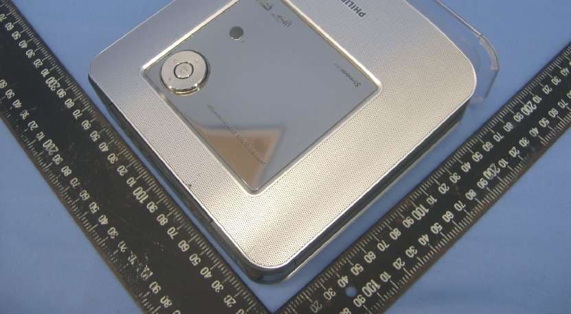
Click to zoom
Application Details
- Equipment Class
- DTS - Digital Transmission System
- Date of Grant
- Aug 09, 2006
- Application Purpose
- Original Equipment
- Date of Application
- Aug 09, 2006
- Equipment Note
- Wireless Music Station
- Frequency Range
- 2412.00000000 - 2462.00000000
- Country
- Taiwan
Documents & Files
Document Text
Text extracted from the exhibit documents filed with the FCC. Open a document above to read the original.
Users Manual
1 User manual 2 Important notes for users in the U.K. Mains plug This apparatus is fitted with an approved 13 Amp plug. To change a fuse in this type of plug, proceed as follows: 1Remove fuse cover and fuse. 2 Fix the new fuse which should be a BS1362 5-Amp, A.S.T.A. or BSI approved type. 3Refit the fuse cover. If the fitted plug is not suitable for your socket outlets, it should be cut off and an appropriate plug fitted in its place. If the mains plug contains a fuse, it should have a value of 5 Amp. If a plug without a fuse is used, the fuse at the distribution board should not be greater than 5 Amp. Note: The severed plug must be disposed, so as to avoid a possible shock hazard due to it being inserted into another 13-Amp socket. How to connect a plug The wires in the mains lead are coloured using the following codes: blue = neutral (N), brown = live (L). OAs these colours may not correspond with the colour markings identifying the terminals in your plug, proceed as follows: – Connect the blue wire to the terminal marked N or coloured black. – Connect the brown wire to the terminal marked L or coloured red. – Do not connect either wire to the earth terminal in the plug, marked E (or e) or coloured green (or green and yellow). Before replacing the plug cover, make sure that the cord grip is clamped over the sheath of the lead, and not simply over the two wires. Copyright in the U.K. Recording and playback of any materials may require consent. See Copyright Act 1956 and The Performer’s Protection Acts 1958 to 1972. Norge Typeskilt finnes på apparatens bakside. Observer: Nettbryteren er sekundert innkoplet. Den innebygde netdelen er derfor ikke frakoplet nettet så lenge apparatet er tilsluttet nettkontakten. For å redusere faren for brann eller elektrisk støt, skal apparatet ikke utsettes for regn eller fuktighet. 3 LGPL Library written offer This product contains Linux 2.4.27-vrsl, that is made available under the GNU LGPL license version 2.1 (hereafter called "the Library"). Philips Electronics Hong Kong Ltd. hereby offers to deliver or make available, upon request, for a charge no more than the cost of physically performing source distribution, a complete machine-readable copy of the corresponding source code of the Library on a medium customarily used for software interchange. Please contact: Mr. Bin Li BLC Audio PDCC Development 5/F., Philips Electronics Building 5 Science Park East Avenue Hong Kong Science Park Shatin Hong Kong This offer is valid for a period of three years after the date of purchase of this product. GPL Package written offer This product contains Linux 2.4.27-vrsl, that is made available under the GNU GPL license version 2 (hereafter called "the Program"). Philips Electronics Hong Kong Ltd. hereby offers to deliver or make available, upon request, for a charge no more than the cost of physically performing source distribution, a complete machine-readable copy of the corresponding source code of the Program on a medium customarily used for software interchange. Please contact: Mr. Bin Li BLC Audio PDCC Development 5/F., Philips Electronics Building 5 Science Park East Avenue Hong Kong Science Park Shatin Hong Kong This offer is valid for a period of three years after the date of purchase of this product. 4 English General information About WAK3300 Wireless Music Station Clock Radio ______________________ 6 Supplied accessories ________________ 6 Minimum system requirement ________ 6 Philips on-line support ______________ 7 Environmental information ___________ 8 Maintenance ______________________ 8 Safety information _________________ 8 Controls Controls on the Set (Top, front and right panels) ________ 11 Remote control __________________ 12 Preparation Using the remote control __________ 14 To replace the remote control’s battery Using navigation controls ___________ 14 Using alphanumeric keys ___________ 15 Installation Placing WAK3300 ________________ 17 Setting up the system ______________ 17 Connecting to power supply Select languages Set clock Connecting WAK3300 to Philips Wireless Music Center or a UPnP-enabled music server __________________________ 18 Connecting WAK3300 (Station) to Philips Wireless Music Center Connecting WAK3300 to a UPnP-enabled music server Installing FM antenna ______________ 20 Using AC power _________________ 20 Basic functions Switching to standby/on and selecting sound sources ____________________ 21 Switching to power-saving mode _____ 21 Accessing sources/settings from the main menu ___________________ 22 Clock setting _____________________ 22 Adjust clock setting Display clock setting during playback Volume control __________________ 23 MUTE _________________________ 23 Sound control ____________________ 23 DSC (Digital Sound Control) Bass adjustment Display adjustment ________________ 24 Selecting languages ________________ 24 Viewing device information __________ 24 Music About MUSIC source ______________ 25 Playing MUSIC source ______________ 25 Selecting and searching ____________ 26 Select a different option Fast scroll an option list Select a track in current album during playback Different play modes: REPEAT, SHUFFLE ________________ 27 Moving music playback between Philips Wireless Music Center and WAK3300 (Station) ________________________ 28 MUSIC FOLLOWS ME MUSIC BROADCAST Contents 5 English FM radio Tuning to radio stations ____________ 30 Programming radio stations _________ 30 Autostore: automatic programming Manual programming To listen to a preset station Alarm Setting alarm_____________________ 32 Set alarm time Set repeat mode Select alarm sound source Turning on/off the alarm____________ 34 De-activating the alarm temporarily ___ 34 Stop alarm for an 8-minute period Stop alarm for a preset period Network setting Connecting to external Wi-Fi network_ 35 Create a connection profile Edit the connection profile Save preset connection profiles Change the encryption key of a connection profile Device setting Sett…
Text truncated - open the document above for the full version.
Cover Letter(s)
~3469782 (954x1498x16M jpeg)
Cover Letter(s)
From: [email protected] [mailto:[email protected]] Sent: Wednesday, August 09, 2006 1:57 AM To: steve.cheng Cc: [email protected] Subject: FCC&IC done : TCB Review Comments for (B06-0807a- IXM-WAK3300- Universal musicstation) Dear Steve, Thank you for your comments on this application! The following items are our replies for your comments: Question #1: Our client uploaded the revised label sample. Question #2: This is typo and we have revised the FCC& IC test report. Question #3: Our client revised the block diagram file. Question #4: After double check, The EUT's higher power is really at channel 1, and it's higher power density is on channel 6. Question #5: We revised the page 9 of FCC& IC test report. All comments of this FCC& IC project are done! Thanks! Best Regards, Amanda Chu / 朱芳誼 Certification Specialist / ADT Corp. (Hsin Chu Office) Tel: 03-5935343 ext. 1737 Fax: 03-5934728 "steve.cheng" <[email protected]> 2006/08/08 下午 05:07 收件人 [email protected] 副本抄 送 主旨 TCB Review Comments for (B06-0807a- IXM-WAK3300- Universal musicstation) TCB Review Comments for (B06-0807a- IXM-WAK3300- Universal music station) -EMC- Question #1: FCC ID number has been blocked and unable to read. Please remove pointing line from label sample. Question #2: Test Date is July 13 -18, 2006 but the instrument-Tektronix Oscilloscope has already expired on Jun 22, 2006. Please recheck. Question #3: Per FCC 2.1033 (b5): Block diagram need to show frequency of all oscillators, the signal path and frequency shall be indicated at each block...etc. However, such info is not found on submitted block diagram. Please revise block diagram to have required info on it. Question #4: Test report page 52 show higher power at channel 1, but page 58 show higher power density on channel 6. Please explain if this is justifiable. Question #5: Test report page 17 & 19, Please explain what is different between mode 1 and mode 2? Best regards, Steve Cheng Curtis-Straus LLC Email: [email protected]
Cover Letter(s)
FCC-POA (953x1427x16M jpeg)
External Photos
Page 1 CONSTRUCTION PHOTOS OF EUT Page 2
ID Label/Location Info
(Fig. 1) FCC ID: IXM-WAK3300 FCC LABEL LOCATION The label will be permanently affixed at a conspicuous location on the device. LABEL
ID Label/Location Info
BY06UC10260001 10- TEST STATION ID CODE BY-USI VENDOR CODE 26-WEEK CODE 06- YEAR 0001-4 DIGITS SERIAL NUMBER UC- USI CHINA NOTE 1 NOTE2 NOTE1: BARCODE READ:WAK3300/37 NOTE2: BARCODE READ: 12 DIGITAL WIRELESS LAN MAC ADDRESS NOTE3: FCC ID:IXM-WAK3300 IC:4110A-WAK3300 NOTE 3
Internal Photos
Page 3 Page 4 Page 5 Page 6 Page 7 Page 8 Page 9 Page 10 Adapter Model: UP0251P-12PA Page 11 Adapter Model: WN20U-120
Test Report
Report No.: RF950706H031Report Format Version 2.0.4 FCC TEST REPORT REPORT NO.: RF950706H03 MODEL NO.: WAK3300/37 RECEIVED: July 06, 2006 TESTED: July 13 to 18, 2006 ISSUED: July 24, 2006 APPLICANT: UNIVERSAL SCIENTIFIC INDUSTRIAL CO., LTD. ADDRESS: 141, Lane 351, Taiping Road, Sec. 1, Tsao Tuen, Nan-Tou, Taiwan, R.O.C. ISSUED BY: Advance Data Technology Corporation LAB LOCATION: No. 81-1, Lu Liao Keng, 9 Ling, Wu Lung Tsuen, Chiung Lin Hsiang, Hsin Chu Hsien, Taiwan, R.O.C. This test report consists of 72 pages in total. It may be duplicated completely for legal use with the approval of the applicant. It should not be reproduced except in full, without the written approval of our laboratory. The client should not use it to claim product endorsement by CNLA, A2LA or any government agencies. The test results in the report only apply to the tested sample. The test results in this report are traceable to the national or international standards. No. 2177-01 Report No.: RF950706H032Report Format Version 2.0.4 Table of Contents 1CERTIFICATION...........................................................................................4 2SUMMARY OF TEST RESULTS...................................................................5 3GENERAL INFORMATION............................................................................6 3.1GENERAL DESCRIPTION OF EUT..............................................................6 3.2DESCRIPTION OF TEST MODES................................................................8 3.3TEST MODE APPLICABLITY AND TESTED CHANNEL DETAIL:................9 3.4GENERAL DESCRIPTION OF APPLIED STANDARDS..............................11 3.5DESCRIPTION OF SUPPORT UNITS........................................................12 3.6CONFIGURATION OF SYSTEM UNDER TEST.........................................13 4TEST TYPES AND RESULTS.....................................................................14 4.1CONDUCTED EMISSION MEASUREMENT..............................................14 4.1.1LIMITS OF CONDUCTED EMISSION MEASUREMENT............................14 4.1.2TEST INSTRUMENTS.................................................................................14 4.1.3TEST PROCEDURES.................................................................................15 4.1.4TEST SETUP..............................................................................................15 4.1.5EUT OPERATING CONDITIONS................................................................16 4.1.6TEST RESULTS (MODE 1).........................................................................17 4.1.7TEST RESULTS (MODE 2).........................................................................19 4.2RADIATED EMISSION MEASUREMENT...................................................21 4.2.1LIMITS OF RADIATED EMISSION MEASUREMENT.................................21 4.2.2TEST INSTRUMENTS.................................................................................22 4.2.3TEST PROCEDURES.................................................................................23 4.2.4TEST SETUP..............................................................................................24 4.2.5EUT OPERATING CONDITIONS................................................................24 4.2.6TEST RESULTS..........................................................................................25 4.2.7TEST RESULTS - DSSS.............................................................................27 4.2.8TEST RESULTS - OFDM............................................................................34 4.36dB BANDWIDTH MEASUREMENT...........................................................41 4.3.1LIMITS OF 6dB BANDWIDTH MEASUREMENT........................................41 4.3.2TEST INSTRUMENTS.................................................................................41 4.3.3TEST PROCEDURE....................................................................................42 4.3.4TEST SETUP..............................................................................................42 4.3.5EUT OPERATING CONDITIONS................................................................42 4.3.6TEST RESULTS –DSSS..............................................................................43 4.3.7TEST RESULTS-OFDM..............................................................................46 4.4MAXIMUM PEAK OUTPUT POWER..........................................................49 4.4.1LIMITS OF MAXIMUM PEAK OUTPUT POWER MEASUREMENT...........49 4.4.2TEST INSTRUMENTS.................................................................................49 4.4.3TEST PROCEDURES.................................................................................50 Report No.: RF950706H033Report Format Version 2.0.4 4.4.4TEST SETUP..............................................................................................50 4.4.5EUT OPERATING CONDITIONS................................................................50 4.4.6TEST RESULTS – DSSS.............................................................................51 4.4.7TEST RESULTS –OFDM.............................................................................52 4.5POWER SPECTRAL DENSITY MEASUREMENT......................................53 4.5.1LIMITS OF POWER SPECTRAL DENSITY MEASUREMENT....................53 4.5.2TEST INSTRUMENTS.................................................................................53 4.5.3TEST PROCEDURE....................................................................................54 4.5.4TEST SETUP..............................................................................................54 4.5.5EUT OPERATING CONDITIONS................................................................54 4.5.6TEST RESULTS –DSSS..............................................................................55 4.5.7TEST RESULTS –OFDM............................................................…
Text truncated - open the document above for the full version.
Test Setup Photos
Report No.: RF950706H0368Report Format Version 2.0.4 5 PHOTOGRAPHS OF THE TEST CONFIGURATION CONDUCTED EMISSION TEST Report No.: RF950706H0369Report Format Version 2.0.4 RADIATED EMISSION TEST (MODE 1) Report No.: RF950706H0370Report Format Version 2.0.4 RADIATED EMISSION TEST (MODE 2)
Contact Information
Applicant
Martin Shih(Section Manager)
Technical Contact
Advance Data Technology Corporation (Hsin Chu)Eric Lin
[email protected]886-3-593-5343
81-1 Luliaoken, 9th Lin, Wulung Tsuen Chiunglin · Hsinchu · Taiwan
Non-Technical Contact
Advance Data Technology CorporationEric Lin
[email protected]886-3-593-5343
Test Firm
Bureau Veritas CPS (H.K.) Ltd. Taoyuan BranchRichard Chen
Technical Specifications
| # | Rule Parts | Frequency Range | Power Output |
|---|---|---|---|
| 1 | 15C | 2.41 GHz - 2.46 GHz | 127.00 mW |
Other Applications from Universal Scientific Industrial Co., Ltd.
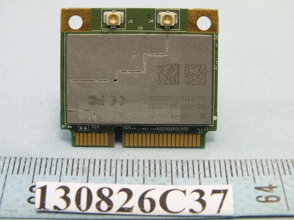
IXM-UNA-P3
Nov 21, 20133G Module
Equipment Class
PCB - PCS Licensed Transmitter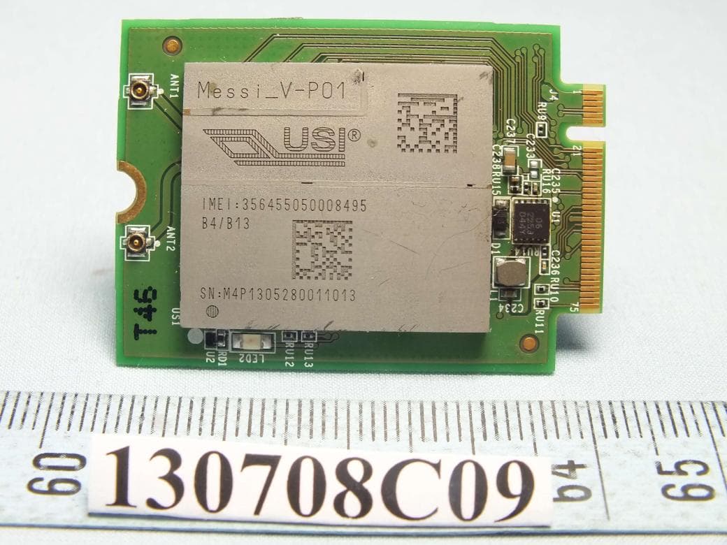
IXMMESSI-V
Sep 29, 2013LTE Module
Equipment Class
JBP - Part 15 Class B Computing Device Peripheral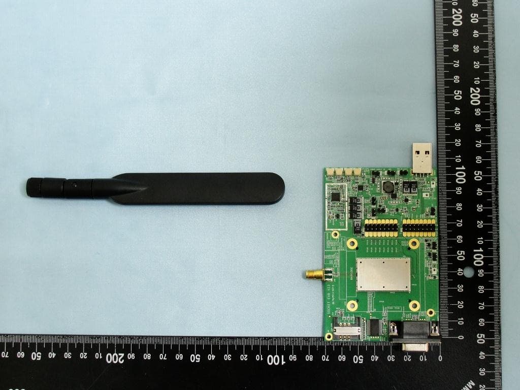
IXM-UNA850
Oct 01, 2012UNA 850 module
Equipment Class
PCB - PCS Licensed Transmitter
IXM-UNA900
Apr 19, 2012WWAN Module
Equipment Class
PCB - PCS Licensed Transmitter
IXMUGNAS-P3
Jul 28, 2011NETWORK ATTACHED STORAGE
Equipment Class
DTS - Digital Transmission System