IXMB2B114800IEEE 802. 11b WLAN Board-to-Board Card
Universal Scientific Industrial Co., Ltd.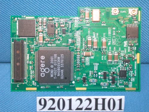
Click to zoom
Application Details
- Equipment Class
- DTS - Digital Transmission System
- Date of Grant
- Feb 23, 2003
- Application Purpose
- Original Equipment
- Date of Application
- Feb 23, 2003
- Equipment Note
- IEEE 802. 11b WLAN Board-to-Board Card
- Frequency Range
- 2412.00000000 - 2462.00000000
- Country
- Taiwan
Documents & Files
Document Text
Text extracted from the exhibit documents filed with the FCC. Open a document above to read the original.
Users Manual
USI WLAN Card 802.11b 2.4GHz Quick Start Guide Configure the Wireless Network To configure the wireless network in a PocketPC environment: 1.Ta p Start Settings System tab. 2.Tap the USI WLAN Card icon to run the Wireless Network- ing Setting utility. 3. Select, add, or delete a profile: a. Select a profile from the drop-down menu, and tap OK to switch your station from one wireless network to another.
Users Manual
b. Tap Add or Edit to add or edit the selected profile. c. Tap Delete to delete the selected profile. 4. Ta p Next, and set the Network Name. 5. Tap Next, and configre your security settings. 6. Ta p Next, and turn Power Management on or off. 7. Click finish. Finding Information • For more information, see the User's Guide on the CD that came with the card. • For the latest information, go to the USI website at www.usi.com.tw The Identification of the Product : Product Name : IEEE 802.11b WLAN Board-to-Board Card Model Number : B2B114800 Technical Support : Universal Scientific Industrial Co., Ltd. Address : 10F, 420, Keelung Road, Sec. 1, Taipei, Taiwan Telephone : +886-2-2345-5006 Fax : +886-2-2345-5191 E-mail : [email protected] Technical Support in the US : Address : 3590 Peterson Way, Santa Clara, CA 95054, USA Telephone : +1-408-986-6589 E-mail : [email protected] Federal Communication Commission Interference Statement This equipment has been tested and found to comply with the limits for a Class B digital device, pursuant to Part 15 of the FCC Rules. These limits are designed to provide reasonable protection against harmful interference in a residential installation. This equipment generates, uses and can radiate radio frequency energy and, if not installed and used in accordance with the instructions, may cause harmful interference to radio communications. However, there is no guarantee that interference will not occur in a particular installation. If this equipment does cause harmful interference to radio or television reception, which can be determined by turning the equipment off and on, the user is encouraged to try to correct the interference by one of the following measures: - Reorient or relocate the receiving antenna. - Increase the separation between the equipment and receiver. - Connect the equipment into an outlet on a circuit different from that to which the receiver is connected. - Consult the dealer or an experienced radio/TV technician for help. FCC Caution: To assure continued compliance, any changes or modifications not expressly approved by the party responsible for compliance could void the user's authority to operate this equipment. This device complies with Part 15 of the FCC Rules. Operation is subject to the following two conditions: (1) This device may not cause harmful interference, and (2) this device must accept any interference received, including interference that may cause undesired operation. IMPORTANT NOTE: FCC Radiation Exposure Statement: This equipment complies with FCC radiation exposure limits set forth for an uncontrolled environment. This equipment should be installed and operated with minimum distance 20cm between the radiator & your body. Information in this document is subject to change without notice. 2003 Universal Scientific Industrial Co.,Ltd. All rights reserved. Reproduction in any manner whatso- ever without the written permission of USI is strictly forbidden.
External Photos
Page 1 CONSTRUCTION PHOTOS OF EUT Antenna Type: PIFA Antenna Page 2 Page 3 Page 4 Antenna Type: Inverted F Antenna Page 5 Page 6 Page 7 Page 8
Internal Photos
Page 1 CONSTRUCTION PHOTOS OF EUT Antenna Type: PIFA Antenna Page 2 Page 3 Page 4 Antenna Type: Inverted F Antenna Page 5 Page 6 Page 7 Page 8
Operational Description
FCC ID: IXMB2B114800 Report No.: RF920122H01 ADT No.: 920122H01 Operational Description The transmitter of the EUT (IEEE 802.11b WLAN Board-to-Board Card) is powered by host equipment via a PCMCIA interface (60 pin board to board connector). The antenna is PIFA Antenna & Inverted F Antenna both with I-Pex connectors. This project is seeking the authorization of limited module approval specific to mobile host environment. The other instruction, please have a look at the users manual. DSSS Information This device is Direct Sequence Spread Spectrum, the data is mixed by pseudorandom code which is an orthogonal code. The mixed data is digital modulated by BPSK and QPSK technique depends on the data rates. The CCK coding is applied for increasing the data rate, and also the processing gain will be increased. The bit rates are 1,2,5.5,11Mbps, the symbol rates are 1,1,1.375,1.375Mbps, the chip rates are always 11Mbps. So, the Chip/symbol is 11,11,8 and 8 respectively. Although is higher bit rate, the processing gain is lower than 10, but the CCK coding used in higher bit rate will provide 2.2dB coding gain.
Test Report
FCC ID: IXMB2B114800 Report No.: RF920122H011Issued: Feb. 14, 2003 ADT No.: 920122H01 FCC TEST REPORT REPORT NO.: RF920122H01 MODEL NO.: B2B114800 RECEIVED: Jan. 22, 2003 TESTED: Jan. 22 to Feb. 11, 2003 APPLICANT: UNIVERSAL SCIENTIFIC INDUSTRIAL CO., LTD. ADDRESS: 141, Lane 351, Taiping Road, Sec. 1, Tsao Tuen, Nan-Tou, Taiwan, R.O.C. ISSUED BY: Advance Data Technology Corporation LAB LOCATION: No. 81-1, Lu Liao Keng, 9 Ling, Wu Lung Tsuen, Chiung Lin Hsiang, Hsin Chu Hsien, Taiwan, R.O.C. This test report consists of 55 pages in total. It may be duplicated completely for legal use with the approval of the applicant. It should not be reproduced except in full, without the written approval of our laboratory. The client should not use it to claim product endorsement by CNLA, NVLAP or any government agencies. The test results in the report only apply to the tested sample. 0536 ILAC MRA Lab Code: 200376-0 FCC ID: IXMB2B114800 Report No.: RF920122H012Issued: Feb. 14, 2003 ADT No.: 920122H01 Table of Contents 1CERTIFICATION.......................................................................................................4 2SUMMARY OF TEST RESULTS............................................................................5 3GENERAL INFORMATION.....................................................................................6 3.1GENERAL DESCRIPTION OF EUT......................................................................6 3.2DESCRIPTION OF TEST MODES........................................................................7 3.3GENERAL DESCRIPTION OF APPLIED STANDARDS...................................7 3.4DESCRIPTION OF SUPPORT UNITS..................................................................8 4TEST TYPES AND RESULTS................................................................................9 4.1CONDUCTED EMISSION MEASUREMENT.......................................................9 4.1.1LIMITS OF CONDUCTED EMISSION MEASUREMENT..................................9 4.1.2TEST INSTRUMENTS.............................................................................................9 4.1.3TEST SETUP..........................................................................................................10 4.1.4EUT OPERATING CONDITIONS........................................................................11 4.1.5TEST RESULTS......................................................................................................12 4.2RADIATED EMISSION MEASUREMENT..........................................................18 4.2.1LIMITS OF RADIATED EMISSION MEASUREMENT......................................18 4.2.2TEST INSTRUMENTS...........................................................................................19 4.2.3TEST PROCEDURES...........................................................................................20 4.2.4TEST SETUP..........................................................................................................21 4.2.5EUT OPERATING CONDITIONS........................................................................21 4.2.6TEST RESULTS (A)...............................................................................................22 4.2.7TEST RESULTS (B)...............................................................................................27 4.36dB BANDWIDTH MEASUREMENT..................................................................32 4.3.1LIMITS OF 6dB BANDWIDTH MEASUREMENT..............................................32 4.3.2TEST INSTRUMENTS...........................................................................................32 4.3.3TEST PROCEDURE..............................................................................................33 4.3.4TEST SETUP..........................................................................................................33 4.3.5EUT OPERATING CONDITIONS........................................................................33 4.3.6TEST RESULTS......................................................................................................34 4.4MAXIMUM PEAK OUTPUT POWER..................................................................38 4.4.1LIMITS OF MAXIMUM PEAK OUTPUT POWER MEASUREMENT.............38 4.4.2TEST INSTRUMENTS...........................................................................................38 4.4.3TEST PROCEDURES...........................................................................................39 4.4.4TEST SETUP..........................................................................................................39 4.4.5EUT OPERATING CONDITIONS........................................................................39 FCC ID: IXMB2B114800 Report No.: RF920122H013Issued: Feb. 14, 2003 ADT No.: 920122H01 4.4.6TEST RESULTS......................................................................................................40 4.5POWER SPECTRAL DENSITY MEASUREMENT...........................................41 4.5.1LIMITS OF POWER SPECTRAL DENSITY MEASUREMENT.......................41 4.5.2TEST INSTRUMENTS...........................................................................................41 4.5.3TEST PROCEDURE..............................................................................................42 4.5.4TEST SETUP..........................................................................................................42 4.5.5EUT OPERATING CONDITIONS........................................................................42 4.5.6TEST RESULTS......................................................................................................43 4.6BAND EDGES MEASUREMENT.........................................................................47 4.6.1LIMITS OF BAND EDGES MEASUREMENT....................................................47 4.6.2TEST INSTRUMENTS...........................................................................................47 4.6.3TEST P…
Text truncated - open the document above for the full version.
Test Setup Photos
FCC ID: IXMB2B114800 Report No.: RF920122H0152Issued: Feb. 14, 2003 ADT No.: 920122H01 5 PHOTOGRAPHS OF THE TEST CONFIGURATION CONDUCTED EMISSION TEST FCC ID: IXMB2B114800 Report No.: RF920122H0153Issued: Feb. 14, 2003 ADT No.: 920122H01 RADIATED EMISSION TEST FCC ID: IXMB2B114800 Report No.: RF920122H0154Issued: Feb. 14, 2003 ADT No.: 920122H01
Contact Information
Applicant
Martin Shih(Section Manager)
Technical Contact
Advance Data Technology CorporationEric Lin
[email protected]+886 3 593 5343
81-1 Luliaoken, 9th Lin, Wulung Tsuen Chiunglin · Hsinchu · Taiwan
Test Firm
Bureau Veritas CPS (H.K.) Ltd. Taoyuan BranchRichard Chen
Technical Specifications
| # | Rule Parts | Frequency Range | Power Output |
|---|---|---|---|
| 1 | 15C | 2.41 GHz - 2.46 GHz | 24.37 mW |
Other Applications from Universal Scientific Industrial Co., Ltd.
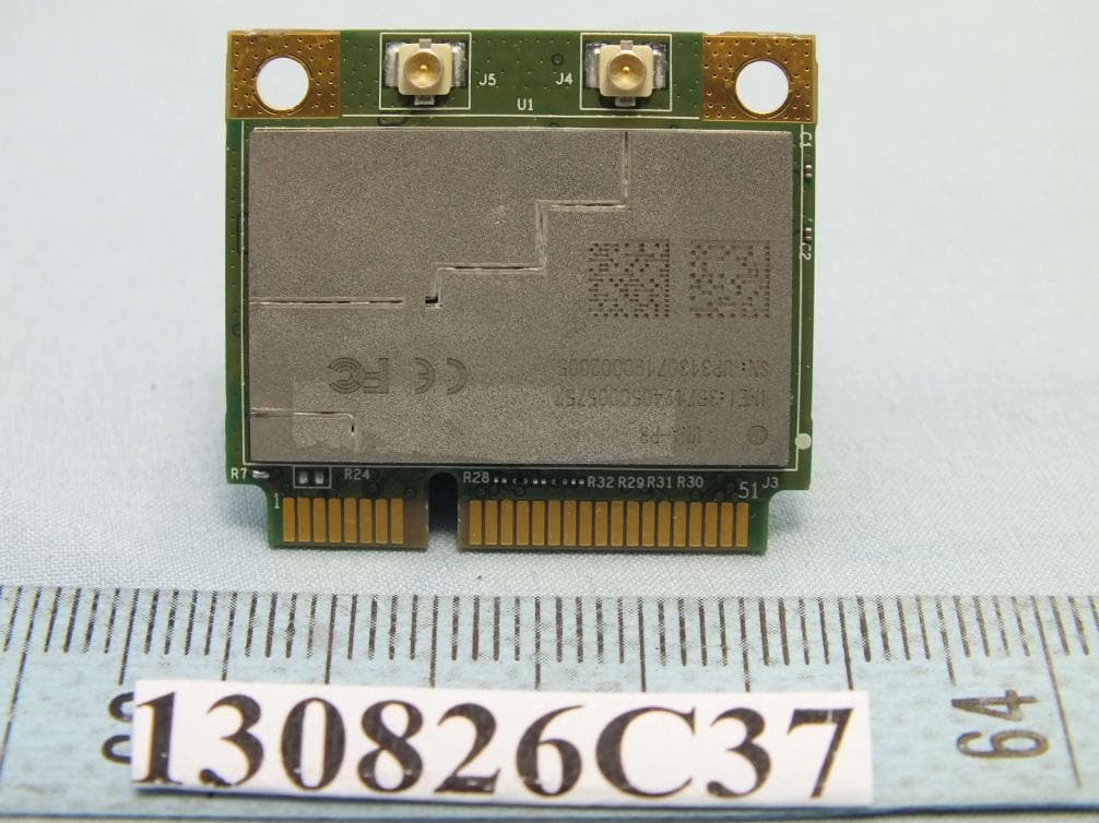
IXM-UNA-P3
Nov 21, 20133G Module
Equipment Class
PCB - PCS Licensed Transmitter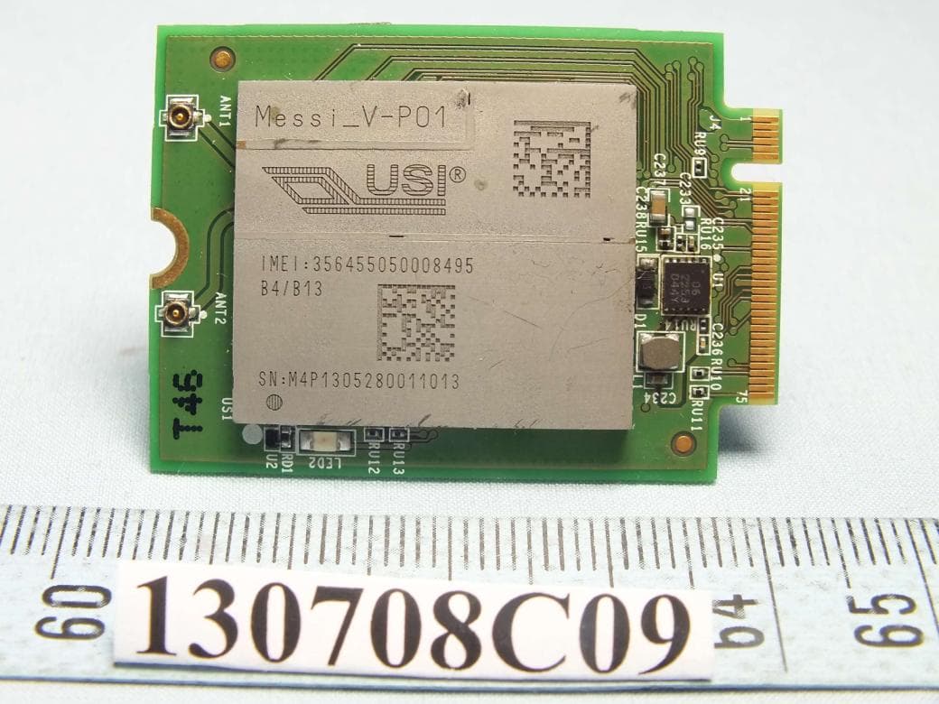
IXMMESSI-V
Sep 29, 2013LTE Module
Equipment Class
JBP - Part 15 Class B Computing Device Peripheral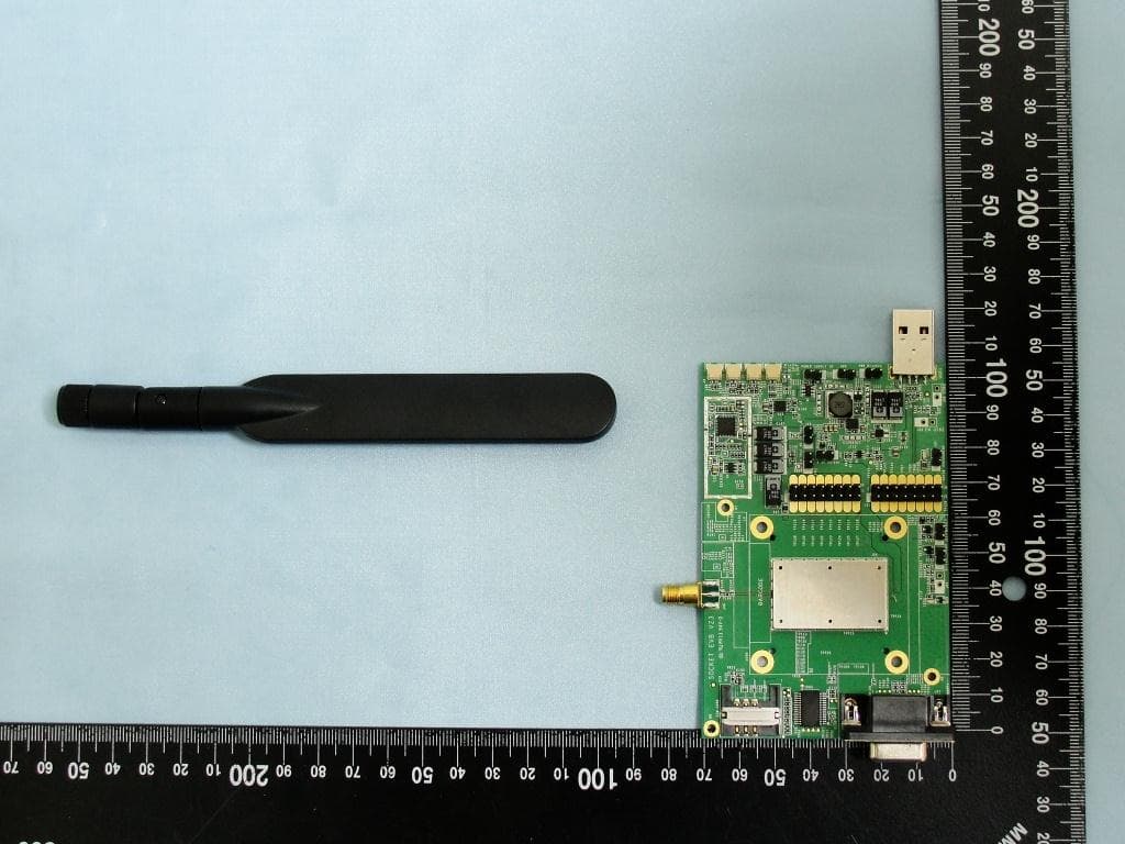
IXM-UNA850
Oct 01, 2012UNA 850 module
Equipment Class
PCB - PCS Licensed Transmitter
IXM-UNA900
Apr 19, 2012WWAN Module
Equipment Class
PCB - PCS Licensed Transmitter
IXMUGNAS-P3
Jul 28, 2011NETWORK ATTACHED STORAGE
Equipment Class
DTS - Digital Transmission System