IXMBM6621R4Mini-PCI WLAN
Universal Scientific Industrial Co., Ltd.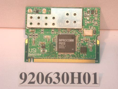
Click to zoom
Application Details
- Equipment Class
- DTS - Digital Transmission System
- Date of Grant
- Jul 16, 2003
- Application Purpose
- Original Equipment
- Date of Application
- Jul 16, 2003
- Equipment Note
- Mini-PCI WLAN
- Frequency Range
- 2412.00000000 - 2462.00000000
- Country
- Taiwan
Documents & Files
Document Text
Text extracted from the exhibit documents filed with the FCC. Open a document above to read the original.
Users Manual
2003/7/9 1 Integrated Baseband and MAC Solution IEEE 802.11b WLAN MP-B-IP-00 Configuration Utility User Guide Table of Contents 2003/7/9 2 Table of Contents .................................................................................................................................... 1 Introduction & Form Factors ................................................................................................................... 3 Installation for Windows XP .................................................................................................................... 4 Installation for Windows 2000................................................................................................................. 7 Installation for Windows 98SE/ME ....................................................................................................... 10 Utility Usage .......................................................................................................................................... 12 Status ......................................................................................................................................... 13 Site Survey................................................................................................................................. 14 General ...................................................................................................................................... 15 Encryption .................................................................................................................................. 15 Advanced ................................................................................................................................... 15 Statistics ..................................................................................................................................... 16 FCC statement ........................................................................................................................... 16 2003/7/9 3 Introduction & Form Factors Introduction The Wireless LAN Configuration Utility is a powerful application that helps you to configure USI MP-B-IP-00 WLAN Mini-PCI card and monitor the statistics of the communication status. Unlike the standard method of configuring the card via the operating system utilities, this application permits the dynamic modification of the configuration parameters while the card is operating. It also offers more configuration options. INPROCOMM offers the Wireless LAN Configuration Utility for Windows 98SE/Me/2000/XP. Evaluation Board Mini-PCI USI MP-B-IP-00 Mini-PCI 2003/7/9 4 Installation for Windows XP 1. Read this First If your hardware came with an installation CD or floppy disk, choose “Install the software automatically (Recommended)” and press cancel. 1.1 How to Install IPN2120 WLAN Utility & Driver in Windows XP environment 1.1.1 Double click the “setup” located in “\Wireless LAN Configuration Utility\” 1.1.2 The program will automatically proceed with installing 2003/7/9 5 1.1.3 Press “Next” to continue 1.1.4 Review “The License Agreement” then press “Next” 1.1.5 Press “Install” to continue the install program 1.1.6 Please wait for the installing 1.1.7 Press “ finish ” to complete the installation. 2003/7/9 6 2003/7/9 7 Installation for Windows 2000 1.2 How to Install IPN2120 WLAN Utility & Driver in Windows 2000 environment 1.2.1 Detecting for a new hardware, press “finish” to run automatically installation 2003/7/9 8 1.2.2 Double click the “setup” located in “\Wireless LAN Configuration Utility\” 1.2.3 Install Shield is installing the program. 1.2.4 Press “Next” to continue 1.2.5 Review “The License Agreement” then press “Next” 1.2.6 Press “Install” to continue the install program 2003/7/9 9 1.2.7 Press “finish” to complete the installation 2003/7/9 10 Installation for Windows 98SE/ME 1.3 How to Install IPN2120 WLAN Utility & Driver in Windows 98SE/ME environment 1.3.1 Press cancel to run an automatic installation 1.3.2 Double click the “setup” located in “\Wireless LAN Configuration Utility\” 1.3.3 Install shield is installing the program 1.3.4 Press “Next” to continue 1.3.5 Review “The License Agreement” then press “Next” 1.3.6 Press “Install” to continue the install program 2003/7/9 11 1.3.7 Press “finish” to complete the installation 2003/7/9 12 Utility Usage 1.4 Using the Wireless LAN Configuration Utility The Wireless LAN Configuration Utility appears as an icon on the system tray of Windows while the card is running. You can open it by clicking on the icon. The icon is appeared as bar diagram with different color and level for representing different connection status. While the station is not associated with other STA/AP, the icon will appear as an empty (blank) bar diagram. Once it is associated, it will appear as different color for different level of signal strength (RSSI). There are 3 levels of icons to represent the signal strength, the green one (signal strength from 100%-50%), the yellow one (50%-25%), and the red one (below 25%). The Wireless LAN Configuration Utility is a highly integrated application include the following main options (tabs), Status Site Survey Statistics About 2003/7/9 13 Status A typical screen of the application in Infrastructure mode is shown in Figure 1-1. The configuration parameters are shown at the top of the screen. In order to change the configuration parameters press the “Configuration” button, then it will pop-up a dialog for you to input your settings. (Figuration 1-3, 1-4, 1-5) 1. Profile Name 2. SSID 3. Link Status 4. Network Type 5. Channel 6. Tx Rate 7. Signal strength, link quality 8. Network Address 9. Link Quality Network Address section shows the current Network status such as the MAC address, DHCP (Enable or not), IP address, Subnet Mask address, Gateway Address and DNS server address that you can easily monitor these settings without the “IPCONFIG” provided by Windows. Figu…
Text truncated - open the document above for the full version.
Cover Letter(s)
FCC ID: IXMBM6621R4 ADT No.920630H01 Modular Approval Request Letter Advance Data Technology Jul. 03, 2003 Dear Application Examiner, UNIVERSAL SCIENTIFIC INDUSTRIAL CO., LTD.’s Mini-PCI WLAN, FCC ID: IXMBM6621R4, would like to have your authorization as a modular approval specific to the mobile device such as Notebook. The requirements of Public Notice DA00- 1407 have been met and shown on the following statements. 1. “The modular transmitter must have its own RF shielding.”: The radio portion of this module has been shielded, please see exhibition External Photo. 2. “The modular transmitter must have buffered modulation/data inputs.” The EUT has buffered data inputs, it is integrated in chip IPN2120A2. 3. “The modular transmitter must have its own power supply regulation.” The chips RF converter which will influence the frequency radiation, have to be 2.8V DC powered. The mini-pci interface provides 3.3VDC, so there are regulators in front of these chips, the part number of this regulator is NCP500. 4. “The modular transmitter must comply with the antenna requirements of section 15.203 and 15.204(C).” The EUT meets the FCC antenna requirements. The spurious emission, unique antenna connector and photo of antennas are shown in the test report. 5. “The modular transmitter must be tested in a stand-alone configuration” The EUT was tested in a stand-alone configuration via a PCIMCIA adapter card. Please see section Photographs of Test Configuration in the test report. 6. “The modular transmitter must be labeled with its own FCC ID number.” Please see exhibition Label Sample for the FCC ID of this module. And also in the exhibition Users Manual, there are instructions give to the OEM on how to label the end product. FCC ID: IXMBM6621R4 ADT No.920630H01 7. “The modular transmitter must comply with any specific rule or operating requirements applicable to the transmitter and the manufacturer must provide adequate instructions along with the module to explain any such requirements.” The EUT is compliant with all applicable FCC rules. Detail instructions for maintaining compliance are given in the Users Manual. 8. “The modular transmitter must comply with any applicable RF exposure requirements.” The EUT is compliant with all applicable RF exposure requirements. RF Exposure is addressed in the RF exposure exhibition. Please contact me if you have any further questions. Thanks for your attention. Best Regards, Eric Lin Manager of Hsinchu Certification Service Div. Advance Data Technology
External Photos
Page 1 CONSTRUCTION PHOTOS OF EUT Page 2
ID Label/Location Info
1 2 3 4 5 A A B B C C D D E E F F SOURCE ORGANIZATION TITLE: USI MP-B-IP-00 Label proposal TAIWAN / COM MODEL NO 4473-117200 DWG NO N/a DESIGNER DATESCALE: UNIT: mm Michael_Chang 07/08/03 USI P/N SHEETREV A1 APP BY DATE G NO DESCRIPTION DATE Unless otherwise Tolerance specified ± 1.0 N/A 1 A1 G 1 2 3 4 5 Type A label Type B label Country Label 1.Material:Facestock:PVC 2.Color:White Note: 3.Thickness: 0.12 ±0.01mm. 4.LABEL GAP : 15mm S/N:aaaaaaaaaaaa USI P/N:4473-117200-20 MAC:0123456789AB Bar code for MAC Bar code for S/N S/N:aaaaaaaaaaaa USI MP-B-IP-00 801.11b Mini-PCI MAC:0123456789AB Bar code for MAC T/N: Bar code for T/N tttttttt USI P/N:4473-117200-20 Label ALabel B Label A: aaaaaaaaaaaa: 12-digit number USI serial number. MAC address in HR text and barcode(Code 39) MAC address in HR text and barcode(Code 39) aaaaaaaaaaaa: 12-digit number USI serial number. Label A: tttttttt: 8-digit USI trace number Trace Number in HR text and barcode(Code 39) 5. Raw Material Spec please check 59-510172-01 23451 12345 A B C D E F G H A B C D E F G H DESCRIPTION A9 NO A2 A3 A4 A7 A6 A5 A8 UNIT: TAIWAN/COM/MD SOURCE ORGANIZATION Universal Scientific Industrial Co.,Ltd. USI R DATE Unless otherwise tolerence specified ± MODEL NO TITLE DESIGNER APP BY DATE DATE USI P/N N/A SCALE: 1/1 DWG NO REV A1 mm 1/1 SHEET Module label for IPC Mini-PCI 4473-117200N/A Michael Chang 7/4/03
ID Label/Location Info
1 2 3 4 5 A A B B C C D D E E F F SOURCE ORGANIZATION TITLE: USI MP-B-IP-00 Label proposal TAIWAN / COM MODEL NO 4473-117200 DWG NO N/a DESIGNER DATESCALE: UNIT: mm Michael_Chang 07/08/03 USI P/N SHEETREV A1 APP BY DATE G NO DESCRIPTION DATE Unless otherwise Tolerance specified ± 1.0 N/A 1 A1 G 1 2 3 4 5 Type A label Type B label Country Label 1.Material:Facestock:PVC 2.Color:White Note: 3.Thickness: 0.12 ±0.01mm. 4.LABEL GAP : 15mm S/N:aaaaaaaaaaaa USI P/N:4473-117200-20 MAC:0123456789AB Bar code for MAC Bar code for S/N S/N:aaaaaaaaaaaa USI MP-B-IP-00 801.11b Mini-PCI MAC:0123456789AB Bar code for MAC T/N: Bar code for T/N tttttttt USI P/N:4473-117200-20 Label ALabel B Label A: aaaaaaaaaaaa: 12-digit number USI serial number. MAC address in HR text and barcode(Code 39) MAC address in HR text and barcode(Code 39) aaaaaaaaaaaa: 12-digit number USI serial number. Label A: tttttttt: 8-digit USI trace number Trace Number in HR text and barcode(Code 39) 5. Raw Material Spec please check 59-510172-01 23451 12345 A B C D E F G H A B C D E F G H DESCRIPTION A9 NO A2 A3 A4 A7 A6 A5 A8 UNIT: TAIWAN/COM/MD SOURCE ORGANIZATION Universal Scientific Industrial Co.,Ltd. USI R DATE Unless otherwise tolerence specified ± MODEL NO TITLE DESIGNER APP BY DATE DATE USI P/N N/A SCALE: 1/1 DWG NO REV A1 mm 1/1 SHEET Module label for IPC Mini-PCI 4473-117200N/A Michael Chang 7/4/03
Internal Photos
Page 1 CONSTRUCTION PHOTOS OF EUT Page 2 Page 3
Operational Description
FCC ID: IXMBM6621R4 ADT No. 920630H01 Operational Description The transmitter of the EUT is powered by Host equipment. The antenna is PIFA Antenna with Hirose connector. The other instruction, please have a look at the users manual. DSSS Information This device is Direct Sequence Spread Spectrum, the data is mixed by pseudorandom code which is an orthogonal code. The mixed data is digital modulated by BPSK and QPSK technique depends on the data rates. The CCK coding is applied for increasing the data rate, and also the processing gain will be increased. The bit rates are 1,2,5.5,11Mbps, the symbol rates are 1,1,1.375,1.375Mbps, the chip rates are always 11Mbps. So, the Chip/symbol is 11,11,8 and 8 respectively. Although is higher bit rate, the processing gain is lower than 10, but the CCK coding used in higher bit rate will provide 2.2dB coding gain.
RF Exposure Info
FCC ID: IXMBM6621R4 Report No.: 920630H01 ADT No. 920630H01 1 RF EXPOSURE REPORT REPORT NO.: RF920630H01 MODEL NO.: MP-B-IP-00 ACCORDING: FCC Guidelines for Human Exposure IEEE C95.1 APPLICANT: UNIVERSAL SCIENTIFIC INDUSTRIAL CO., LTD. ADDRESS: 141, Lane 351, Taiping Road, Sec. 1, Tsao Tuen, Nan-Tou, Taiwan, R.O.C. ISSUED BY: Advance Data Technology Corporation LAB LOCATION: No. 81-1, Lu Liao Keng, 9 Ling, Wu Lung Tsuen, Chiung Lin Hsiang, Hsin Chu Hsien, Taiwan, R.O.C. Lab Code: 200376-0 FCC ID: IXMBM6621R4 Report No.: 920630H01 ADT No. 920630H01 2 RF Exposure Measurement 1. Introduction In this document, we try to prove the safety of radiation harmfulness to the human body for our product. The limit for Maximum Permissible Exposure (MPE) specified in FCC 1.1310 is followed. The Gain of the antenna used in this product is measured in a Fully Anechoic Chamber (FAC) calibrated for antenna measurement in ADT, and also the maximum total power input to the antenna is measured. Through the Friis transmission formula and the maximum gain of the antenna, we can calculate the distance, away from the product, where the limit of MPE is reached. Although the Friis transmission formula is a far field assumption, the calculated result of that is an over-prediction for near field power density. We will take that as the worst case to specify the safety range. 2. RF Exposure Limit According to FCC 1.1310: The criteria listed in the following table shall be used to evaluate the environmental impact of human exposure to radio-frequency (RF) radiation as specified in 1.1307(b) LIMITS FOR MAXIMUM PERMISSIBLE EXPOSURE (MPE) Frequency Range (MHz) Electric Field Strength (V/m) Magnetic Field Strength (A/m) Power Density (mW/cm 2 ) Average Time (minutes) (A)Limits For Occupational / Control Exposures 300-1500......F/3006 1500-100,000......56 (B)Limits For General Population / Uncontrolled Exposure 300-1500......F/15006 1500-100,000......1.030 F = Frequency in MHz FCC ID: IXMBM6621R4 Report No.: 920630H01 ADT No. 920630H01 3 3. Friis Formula Friis transmission formula : Pd = (Pout*G) / (4*pi*r 2 ) where Pd = power density in mW/cm 2 Pout = output power to antenna in mW G = gain of antenna in linear scale Pi = 3.1416 R = distance between observation point and center of the radiator in cm Pd is the limit of MPE, 1 mW/cm 2 . If we know the maximum Gain of the antenna and the total power input to the antenna, through the calculation, we will know the MPE value at distance 20cm. Ref. : David K. Cheng, Field and Wave Electromagnetics, Second Edition, Page 640, Eq. (11-133). 4 EUT Operating condition The software provided by Manufacturer enabled the EUT to transmit and receive data at lowest, middle and highest channel individually. 5. Classification The antenna of this product, under normal use condition, is at least 20cm away from the body of the user. Warning statement to the user for keeping at least 20cm or more separation distance with the antenna should be included in users manual. So, this device is classified as Mobile Device FCC ID: IXMBM6621R4 Report No.: 920630H01 ADT No. 920630H01 4 6 Test Results 6.1 Antenna Gain The maximum Gain measured in Fully Anechoic Chamber are 4Bi or 2.51 (numeric). 6.2 Output Power Into Antenna & RF Exposure value at distance 20cm: Channel Channel Frequency (MHz) Output Power to Antenna (mW) Power Density (mW/cm 2 ) Limit of Power Density (mW/cm 2 ) 1241245.9200.02291.0 6243756.2340.02811.0 11246244.6680.02231.0
Test Report
Report No. 920630H01 ADT No. 920630H01 1 The Measurement of Conducted Spurious Emissions CONDUCTED SPURIOUS EMISSIONS MEASUREMENT 1. LIMITS OF CONDUCTED SPURIOUS EMISSIONS EASUREMENT Below 20dB of the highest emission level of operating band (in 100KHz Resolution Bandwidth, see Section 15.247(c)). Emissions which fall in the restricted bands, as defined in Section 15.205(a), must also comply with the limits specified in Section 15.209(a) (see Section 15.205(c)). 2. TEST INSTRUMENTS Description & ManufacturerModel No.Serial No.Calibrated Until R&S SPECTRUM ANALYZERFSP1093.4495.30Dec. 19, 2003 HIGH PASS FILTER WHK3.1/18G- 10SS SN4Jun. 12, 2004 NOTE: 1.The calibration interval of the above test instruments is 12 months and the calibrations are traceable to NML/ROC and NIST/USA. 3. TEST PROCEDURE 2.5GHz~13GHz: The transmitter output was connected to the spectrum analyzer via a low lose cable and a high pass filter. Set both RBW and VBW of spectrum analyzer to 100 kHz with suitable frequency span including 100 kHz bandwidth from band edge. The band edges was measured and recorded. 13GHz~25GHz: The transmitter output was connected to the spectrum analyzer via a low lose cable. Set both RBW and VBW of spectrum analyzer to 100 kHz with suitable frequency span including 100 kHz bandwidth from band edge. The band edges was measured and recorded. Report No. 920630H01 ADT No. 920630H01 2 4. TEST SETUP 2.5GHz~13GHz: 13GHz~25GHz: 5. EUT OPERATING CONDITIONS The software provided by client to enable the EUT under transmission condition continuously at lowest, middle and highest channel frequencies individually. EUT SPECTRUM ANALYZER EUT SPECTRUM ANALYZER HIGH PASS FILTER Report No. 920630H01 ADT No. 920630H01 3 TEST RESULTS The spectrum plots are attached on the following 4 pages. It shows compliance with the requirement in part 15.247(C),.15.205 and 15.209. Report No. 920630H01 ADT No. 920630H01 4 Ch1 Report No. 920630H01 ADT No. 920630H01 5 Ch1 Report No. 920630H01 ADT No. 920630H01 6 Ch11 Report No. 920630H01 ADT No. 920630H01 7 Ch11
Test Report
FCC ID: IXMBM6621R4 Report No.: RF920630H011Issued: Jul. 11, 2003 ADT No. 920630H01 FCC TEST REPORT REPORT NO.: RF920630H01 MODEL NO.: MP-B-IP-00 RECEIVED: Jun. 30, 2003 TESTED: Jun. 30, 2003 APPLICANT: UNIVERSAL SCIENTIFIC INDUSTRIAL CO., LTD. ADDRESS: 141, Lane 351, Taiping Road, Sec. 1, Tsao Tuen, Nan-Tou, Taiwan, R.O.C. ISSUED BY: Advance Data Technology Corporation LAB LOCATION: No. 81-1, Lu Liao Keng, 9 Ling, Wu Lung Tsuen, Chiung Lin Hsiang, Hsin Chu Hsien, Taiwan, R.O.C. This test report consists of 50 pages in total. It may be duplicated completely for legal use with the approval of the applicant. It should not be reproduced except in full, without the written approval of our laboratory. The client should not use it to claim product endorsement by CNLA, NVLAP or any government agencies. The test results in the report only apply to the tested sample. Lab Code: 200376-0 FCC ID: IXMBM6621R4 Report No.: RF920630H012Issued: Jul. 11, 2003 ADT No. 920630H01 Table of Contents 1CERTIFICATION......................................................................................................4 2SUMMARY OF TEST RESULTS...........................................................................5 3GENERAL INFORMATION....................................................................................6 3.1GENERAL DESCRIPTION OF EUT.....................................................................6 3.2DESCRIPTION OF TEST MODES.......................................................................7 3.3GENERAL DESCRIPTION OF APPLIED STANDARDS..................................7 3.4DESCRIPTION OF SUPPORT UNITS.................................................................8 4TEST TYPES AND RESULTS...............................................................................9 4.1CONDUCTED EMISSION MEASUREMENT......................................................9 4.1.1TEST INSTRUMENTS...............................................................................................9 4.1.2TEST PROCEDURES.............................................................................................10 4.1.3DEVIATION FROM TEST STANDARD...................................................................10 4.1.4TEST SETUP............................................................................................................11 4.1.5EUT OPERATING CONDITIONS............................................................................12 4.1.6TEST RESULTS.......................................................................................................13 4.2RADIATED EMISSION MEASUREMENT.........................................................19 4.2.1LIMITS OF RADIATED EMISSION MEASUREMENT............................................19 4.2.2TEST INSTRUMENTS.............................................................................................20 4.2.3TEST PROCEDURES.............................................................................................21 4.2.4DEVIATION FROM TEST STANDARD...................................................................21 4.2.5TEST SETUP...........................................................................................................22 4.2.6EUT OPERATING CONDITIONS............................................................................22 4.2.7TEST RESULTS.......................................................................................................23 4.36dB BANDWIDTH MEASUREMENT.................................................................27 4.3.1LIMITS OF 6dB BANDWIDTH MEASUREMENT....................................................27 4.3.2TEST INSTRUMENTS.............................................................................................27 4.3.3TEST PROCEDURE................................................................................................28 4.3.4DEVIATION FROM TEST STANDARD...................................................................28 4.3.5TEST SETUP...........................................................................................................28 4.3.6EUT OPERATING CONDITIONS............................................................................28 4.3.7TEST RESULTS.......................................................................................................29 4.4MAXIMUM PEAK OUTPUT POWER.................................................................33 4.4.1LIMITS OF MAXIMUM PEAK OUTPUT POWER MEASUREMENT......................33 4.4.2INSTRUMENTS........................................................................................................33 4.4.3TEST PROCEDURES.............................................................................................34 4.4.4TEST SETUP...........................................................................................................34 4.4.5EUT OPERATING CONDITIONS............................................................................34 FCC ID: IXMBM6621R4 Report No.: RF920630H013Issued: Jul. 11, 2003 ADT No. 920630H01 4.4.6TEST RESULTS.......................................................................................................35 4.4.7LIMITS OF POWER SPECTRAL DENSITY MEASUREMENT...............................36 4.4.8TEST INSTRUMENTS.............................................................................................36 4.4.9TEST PROCEDURE................................................................................................37 4.4.10DEVIATION FROM TEST STANDARD...................................................................37 4.4.11TEST SETUP...........................................................................................................37 4.4.12EUT OPERATING CONDITION...............................................................................37 4.4.13TEST RESULTS.......................................................................................................38 4.5BAND EDGES MEASUREME…
Text truncated - open the document above for the full version.
Test Setup Photos
FCC ID: IXMBM6621R4 Report No.: RF920630H0147Issued: Jul. 11, 2003 ADT No. 920630H01 5 PHOTOGRAPHS OF THE TEST CONFIGURATION CONDUCTED EMISSION TEST FCC ID: IXMBM6621R4 Report No.: RF920630H0148Issued: Jul. 11, 2003 ADT No. 920630H01 RADIATED EMISSION TEST FCC ID: IXMBM6621R4 Report No.: RF920630H0149Issued: Jul. 11, 2003 ADT No. 920630H01
Contact Information
Applicant
Martin Shih(Section Manager)
Technical Contact
Advance Data Technology CorparationEric Lin
[email protected]+886 3 593 5343
81-1 Luliaoken, 9th Lin, Wulung Tsuen Chiunglin · Hsin-Chu · Taiwan
Test Firm
Bureau Veritas CPS (H.K.) Ltd. Taoyuan BranchRichard Chen
Technical Specifications
| # | Rule Parts | Frequency Range | Power Output |
|---|---|---|---|
| 1 | 15C | 2.41 GHz - 2.46 GHz | 56.20 mW |
Other Applications from Universal Scientific Industrial Co., Ltd.
IXM-UNA-P3
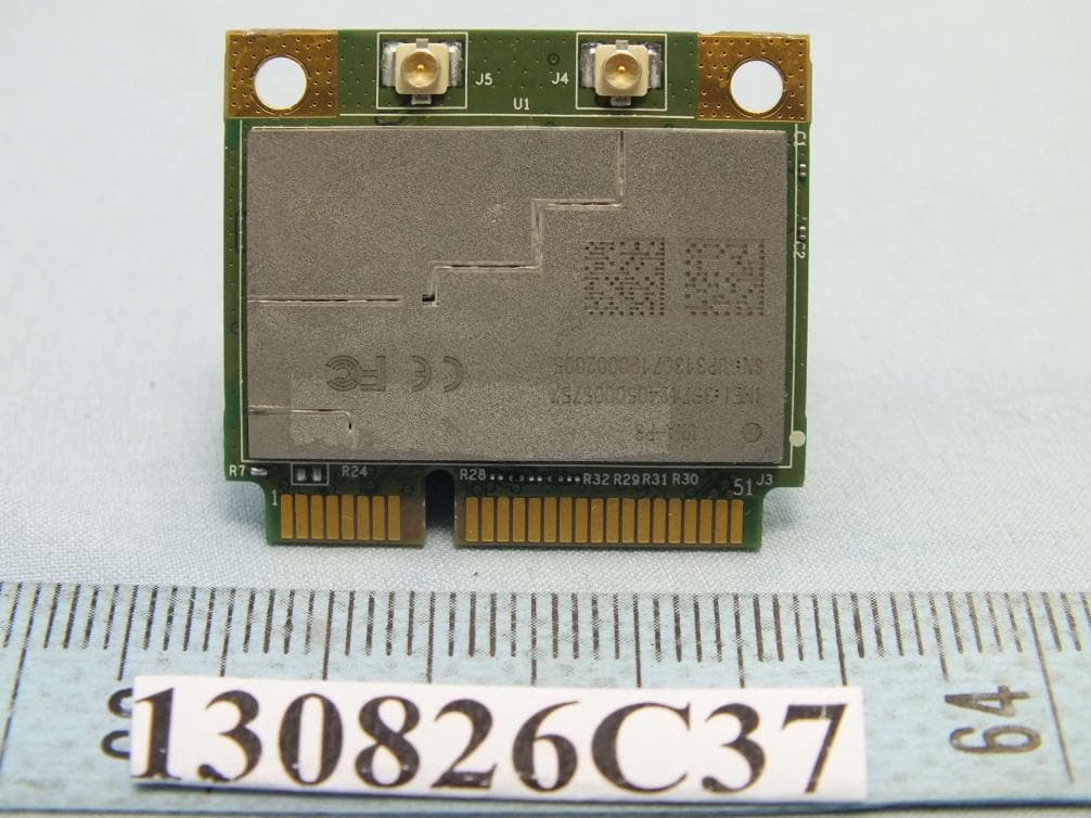
Nov 21, 20133G Module
Equipment Class
PCB - PCS Licensed Transmitter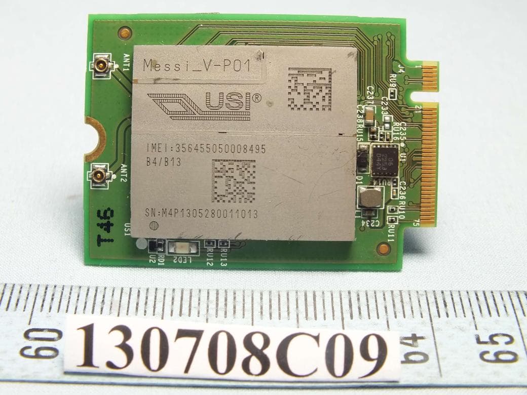
IXMMESSI-V
Sep 29, 2013LTE Module
Equipment Class
JBP - Part 15 Class B Computing Device Peripheral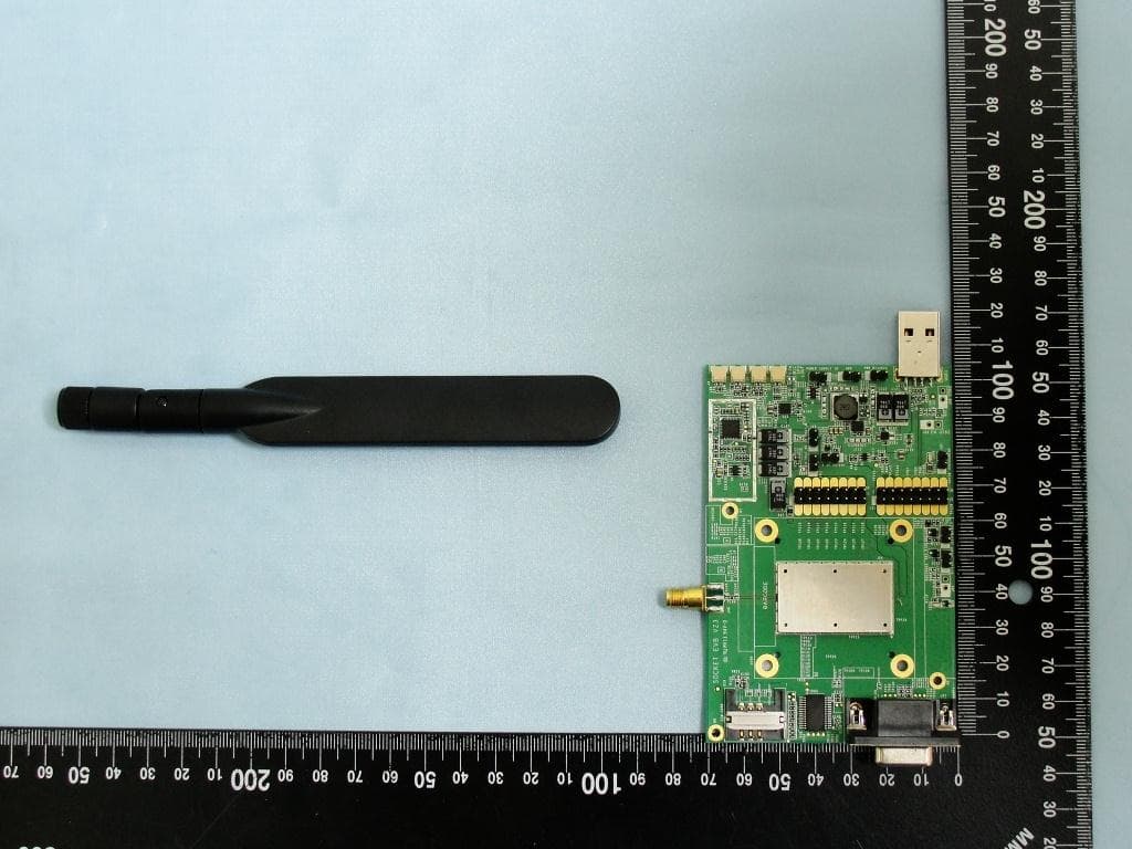
IXM-UNA850
Oct 01, 2012UNA 850 module
Equipment Class
PCB - PCS Licensed Transmitter
IXM-UNA900
Apr 19, 2012WWAN Module
Equipment Class
PCB - PCS Licensed Transmitter
IXMUGNAS-P3
Jul 28, 2011NETWORK ATTACHED STORAGE
Equipment Class
DTS - Digital Transmission System