IXMCB-G-BR-02802.11g Wireless LAN Cardbus Adapter
Universal Scientific Industrial Co., Ltd.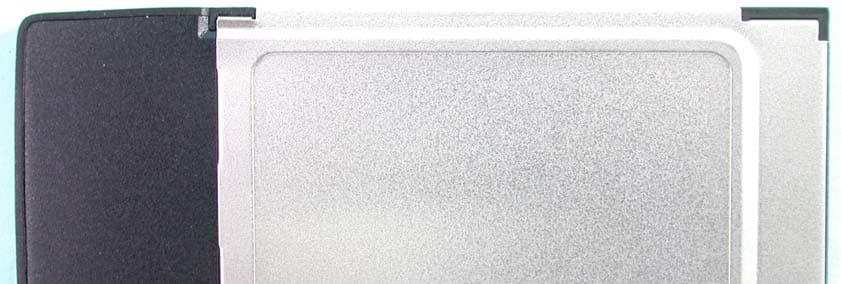
Click to zoom
Application Details
- Equipment Class
- DTS - Digital Transmission System
- Date of Grant
- Oct 28, 2003
- Application Purpose
- Original Equipment
- Date of Application
- Oct 28, 2003
- Equipment Note
- 802.11g Wireless LAN Cardbus Adapter
- Frequency Range
- 2412.00000000 - 2462.00000000
- Country
- Taiwan
Documents & Files
Document Text
Text extracted from the exhibit documents filed with the FCC. Open a document above to read the original.
Users Manual
1 WLAN 802.11g Cardbus Adapter Users Manual V1.0 Copyright© 2003 by separated owners. All Rights Reserved. 2 Contents 1. Introduction......................................................................3 1.1 The Network Type.................................................................4 1.2 Using Your Wireless LAN....................................................... 7 1.3 About Client Manager.............................................................8 1.4 Grossary.............................................................................10 2. Install and Configure a Wireless Network..............................15 2.1 Before You Start..................................................................15 2.2 Software Installation for Windows............................................ 15 2.3 Insert the Cardbus Adaptor.....................................................16 2.4 Configuration the Networks.....................................................16 3. Basic TroubleShooting....................................................................20 4. Technical Support.......................................................................... 23 3 1. Introduction Welcome to the world of wireless computer networks. This document is a short reference guide that will show you how you can: • Use WLAN Cardbus adapters to connect the mobile computers to a wireless network. • Use mobile computers to roam between different locations without losing the wireless connection. • Use the wireless network to share files and printers with other computer users. In a Local Area Network (LAN), you can connect two or more computers to each other. You can use a network to share files or common equipment such as a printer or a modem. In a wired network, you need special cables and networking equipment to connect the computers, but in a wireless network, computers communicate via radio technology that can pass through walls and ceilings. Users connect the wireless computers by assigning a shared Network Name value to each Wireless Client Adapter that belongs to your network. To secure your WLAN Cardbus adapter supports Data Encryption when you transmit data, we recommend that you always enable this feature to protect your network against unauthorized access to your files and communications. The WLAN Cardbus adapter support different network modes such as Peer-to- Peer Group, Act as Base Station, and Base Station Network that allow users to connect to an existing network or start the network. For instructions to install your WLAN Cardbus adapter, please consult the documentation that is included with the hardware. 4 1.1 The Network Type Peer-to-Peer Group Network where Wireless Client devices communicate directly with each other as the following figure shows. Act as Base Station Network where you assign one computer to act as the central point of communication for all wireless computers. The computer in this mode will start it's own wireless network. This type of network for SOHO or small offices provides a larger wireless range than a Peer-to-Peer Group. However you can assign only one computer to act as Base Station. Base Station Network Network where Wireless Client devices communicate with each other through a dedicated Base Station. 5 With this type of network for medium to large enterprises, you can add as many Base Station devices as you like to extend the wireless range. Most Base Station devices also allow you to connect your wireless network to a wired network infrastructure. 6 Network Type Overview Network TypePeer-to-Peer GroupAct As Base StationBase Station Characteristic s • Ideal for home and small offices users. • Ability to share files, printers or Internet connection. • All computers communicate directly with each other • Ideal for small offices and business networks. • Just one computer assigned as the central point of wireless communicate for all computers. • All computers communicate only via the Base Station. • Ability to share files, printers or Internet connection. • Ideal for larger companies, organizations or enterprises. • Addition of a special Base Station device that acts as the central point of wireless communications for all computers. • Able to connect to wired networks and access to central file servers, office printers and corporate email or Internet. Advantages • Easy to setup. • Cost Efficient. • Network remains active as long as two or more wireless computers are operational. • Fairly easy to setup. • Cost efficient. • Extended range. • Extended range. • Scalability for more Base Station devices to extend the range. • Roaming of wireless computers between different locations is supported. • Allow connections to a wired infrastructure or Internet connection. Disadvantages • Limited range.• When the Base Station shuts down, the wireless network disappears. • Does not allow expansion of wireless network with other Base Station devices. • Requires more expertise to install additional features. • Additional cables and networking equipment are required. • Requires more expertise and time to install additional features. 7 1.2 Using your Wireless LAN This section provides general information about: • Configuration Profile to save network settings • Roaming • File and Printer Sharing • Internet Connection Sharing Using Configuration Profiles If you plan to use your wireless Client Station in multiple wireless networks, you can use network configuration profiles to save the settings for each wireless network. For example you can create a Configuration Profile for: • Your office head quarters. • A branch-office. • The private home network. You can use the Configuration Profile to quickly switch between these networks. Roaming Roaming is a key feature of wireless computer networks that you can use to move with a mobile computer between different locations without losing your network connection. In networks that include two or more Base Station devices, the wireless computer will …
Text truncated - open the document above for the full version.
External Photos
Page 1 CONSTRUCTION PHOTOS OF EUT USI CB-G-BR-02 921014R01 USI CB-G-BR-02 921014R01 Page 2 USI CB-G-BR-02 921014R01 USI CB-G-BR-02 921014R01 Page 7 Page 8
ID Label/Location Info
Bottom
Internal Photos
Page 3 Page 4 Page 5 Page 6
Operational Description
FCC ID: IXMCB-G-BR-02 Report No.: RF921014R01 Operational Description This device is a 802.11g Wireless LAN CardBus Adapter which operates in the 2.4Ghz frequency spectrum with throughput of up to 54Mbps which OFDM technique will be applied. If the signal to noise radio is too poor which could not support 54Mbps, the 11Mbps data rate with CCK technique will be applied. The transmitter of the EUT is powered by host equipment. The antenna is printed antenna without antenna connector. The other instruction, please have a look at the users manual.
Test Report
FCC ID: IXMCB-G-BR-02 Report No.: RF921014R011Issued: October 25, 2003 FCC TEST REPORT REPORT NO.: RF921014R01 MODEL NO.: CB-G-BR-02 OEM MODEL NO.: WLI-CB-G54A RECEIVED: Oct. 14, 2003 TESTED: Oct. 14, 2003 APPLICANT: Universal Scientific Industrial Co., Ltd. ADDRESS: 141, Lane 351, Taiping Road, Sec. 1, Tsao Tuen, Nan-Tou, Taiwan, R.O.C. ISSUED BY: Advance Data Technology Corporation LAB LOCATION: 47 14th Lin, Chiapau Tsun, Linko, Taipei, Taiwan, R.O.C. This test report consists of 65 pages in total. It may be duplicated completely for legal use with the approval of the applicant. It should not be reproduced except in full, without the written approval of our laboratory. The client should not use it to claim product endorsement by CNLA, NVLAP or any government agencies. The test results in the report only apply to the tested sample. 0528 ILAC MRA Lab Code: 200102-0 FCC ID: IXMCB-G-BR-02 Report No.: RF921014R012Issued: October 25, 2003 Table of Contents 1CERTIFICATION ..................................................................................................................... 4 2SUMMARY OF TEST RESULTS ............................................................................................ 5 3GENERAL INFORMATION ..................................................................................................... 6 3.1GENERAL DESCRIPTION OF EUT ....................................................................................... 6 3.2DESCRIPTION OF TEST MODES ......................................................................................... 7 3.3GENERAL DESCRIPTION OF APPLIED STANDARDS ........................................................ 7 3.4DESCRIPTION OF SUPPORT UNITS ................................................................................... 8 3.5CONFIGURATION OF SYSTEM UNDER TEST .................................................................... 9 4TEST TYPES AND RESULTS............................................................................................... 10 4.1CONDUCTED EMISSION MEASUREMENT ....................................................................... 10 4.1.1LIMITS OF CONDUCTED EMISSION MEASUREMENT..................................................... 10 4.1.2TEST INSTRUMENTS ..........................................................................................................10 4.1.3TEST PROCEDURES............................................................................................................11 4.1.4DEVIATION FROM TEST STANDARD..................................................................................11 4.1.5TEST SETUP ........................................................................................................................ 12 4.1.6EUT OPERATING CONDITIONS ......................................................................................... 12 4.1.7TEST RESULTS .................................................................................................................... 13 4.2RADIATED EMISSION MEASUREMENT............................................................................. 19 4.2.1LIMITS OF RADIATED EMISSION MEASUREMENT .......................................................... 19 4.2.2TEST INSTRUMENTS ..........................................................................................................20 4.2.3TEST PROCEDURES...........................................................................................................21 4.2.4DEVIATION FROM TEST STANDARD................................................................................. 21 4.2.5TEST SETUP ........................................................................................................................ 22 4.2.6EUT OPERATING CONDITIONS ......................................................................................... 22 4.2.7TEST RESULTS .................................................................................................................... 23 4.2.8TEST RESULTS (A) .............................................................................................................. 25 4.2.9TEST RESULTS (B) .............................................................................................................. 28 4.36dB BANDWIDTH MEASUREMENT .................................................................................... 31 4.3.1LIMITS OF 6dB BANDWIDTH MEASUREMENT ................................................................. 31 4.3.2TEST INSTRUMENTS ..........................................................................................................31 4.3.3TEST PROCEDURE .............................................................................................................31 4.3.4DEVIATION FROM TEST STANDARD................................................................................. 32 4.3.5TEST SETUP ........................................................................................................................ 32 4.3.6EUT OPERATING CONDITIONS ......................................................................................... 32 4.3.7TEST RESULTS (A) .............................................................................................................. 33 4.3.8TEST RESULTS (B) .............................................................................................................. 37 4.4MAXIMUM PEAK OUTPUT POWER.................................................................................... 41 4.4.1LIMITS OF MAXIMUM PEAK OUTPUT POWER MEASUREMENT .................................... 41 4.4.2TEST INSTRUMENTS ..........................................................................................................41 4.4.3TEST PROCEDURES...........................................................................................................42 4.4.4DEVIATION FROM TEST STANDARD..................................................…
Text truncated - open the document above for the full version.
Test Report
FCC ID: IXMCB-G-BR-02 Report No.: SA921014R011Issued: Oct. 24, 2003 SAR TEST REPORT REPORT NO.: SA921014R01 MODEL NO.: CB-G-BR-02, WLI-CB-G54A RECEIVED: Oct. 23 2003 TESTED: Oct. 14 2003 APPLICANT: UNIVERSAL SCIENTIFIC INDUSTRIAL CO., LTD. ADDRESS: 141, Lane 351, Taiping Road, Sec. 1, Tsao Tuen, Nan-Tou, Taiwan, R.O.C. ISSUED BY: Advance Data Technology Corporation LAB LOCATION: 47 14th Lin, Chiapau Tsun, Linko, Taipei, Taiwan, R.O.C. This test report consists of 31 pages in total except Appendix. It may be duplicated completely for legal use with the approval of the applicant. It should not be reproduced except in full, without the written approval of our laboratory. The client should not use it to claim product endorsement by CNLA or any government agencies. The test results in the report only apply to the tested sample. 0528 ILAC MRA FCC ID: IXMCB-G-BR-02 Report No.: SA921014R012Issued: Oct. 24, 2003 Table of Contents 1.CERTIFICATION........................................................................................................................ 3 2.GENERAL INFORMATION........................................................................................................ 4 2.1GENERAL DESCRIPTION OF EUT.......................................................................................... 4 2.2GENERAL DESCRIPTION OF APPLIED STANDARDS ........................................................... 5 2.3GENERAL INOFRMATION OF THE SAR SYSTEM ................................................................. 5 2.4GENERAL DESCRIPTION OF THE SPATIAL PEAK SAR EVALUATION ............................... 9 3.DESCRIPTION OF TEST MODES AND CONFIGURATIONS................................................ 13 4.DESCRIPTION OF SUPPORT UNITS .................................................................................... 14 5.TEST RESULTS ...................................................................................................................... 15 5.1TEST PROCEDURES .............................................................................................................15 5.2MEASURED SAR RESULT ..................................................................................................... 16 5.3SAR LIMITS ............................................................................................................................. 18 5.4RECIPES FOR TISSUE SIMULATING LIQUIDS .................................................................... 18 5.5TEST EQUIPMENT FOR TISSUE PROPERTY...................................................................... 20 6.SYSTEM VALIDATION ............................................................................................................21 6.1TEST EQUIPMENT ................................................................................................................. 21 6.2TEST PROCEDURE................................................................................................................ 21 6.3VALIDATION RESULT............................................................................................................. 23 6.4SYSTEM VALIDATION UNCERTAINTIES .............................................................................. 24 7.MEASUREMENT SAR PROCEDURE UNCERTAINTIES ...................................................... 25 7.1PROBE CALIBRATION UNCERTAINTY ................................................................................. 25 7.2ISOTROPY UNCERTAINTY .................................................................................................... 25 7.3BOUNDARY EFFECT UNCERTAINTY ................................................................................... 26 7.4PROBE LINEARITY UNCERTAINTY ...................................................................................... 26 7.5READOUT ELECTRONICS UNCERTAINTY .......................................................................... 26 7.6RESPONSE TIME UNCERTAINTY ......................................................................................... 27 7.7INTEGRATION TIME UNCERTAINTY .................................................................................... 28 7.8PROBE POSITIONER MECHANICAL TOLERANCE ............................................................. 28 7.9PROBE POSITIONING............................................................................................................29 7.10 PHANTOM UNCERTAINTY..................................................................................................... 29 7.11 DASY4 UNCERTAINTY BUDGET........................................................................................... 30 8.INFORMATION ON THE TESTING LABORATORIES............................................................ 31 APPENDIX A: TEST CONFIGURATIONS AND TEST DATA APPENDIX B: ADT SAR MEASUREMENT SYSTEM APPENDIX C: PHOTOGRAPHS OF SYSTEM VALIDATION APPENDIX D: SYSTEM CERTIFICATE & CALIBRATION FCC ID: IXMCB-G-BR-02 Report No.: SA921014R013Issued: Oct. 24, 2003 1. CERTIFICATION PRODUCT : 802.11g Wireless LAN CardBus Adapter MODEL NO. : CB-G-BR-02 (for Brand: USI) WLI-CB-G54A (for Brand: BUFFALO INC.) APPLICANT : UNIVERSAL SCIENTIFIC INDUSTRIAL CO., LTD. TEST ITEM : Engineering sample STANDARDS : 47 CFR Part 2 (Section 2.1093), FCC OET Bulletin 65, Supplement C (01-01), RSS-102 We, Advance Data Technology Corporation, hereby certify that one sample of the designation has been tested in our facility on Oct. 23, 2003. The test record, data evaluation and Equipment Under Test (EUT) configurations represented herein are true and accurate, and it was tested according to the standards listed above. This device was found to be in compliance with the Specific Absorption Rate (SAR) requirement specified in FCC part 2.1093 under General Population / Uncontrolled Exposure condition. FCC ID: IXMCB-G-BR-02 Report No.: SA921014R014Issued: Oct. 24, 2003 2. GENERAL INFORMATION 2.1 GENERAL DESCRIPTION OF EUT PRODUCT 802.11g…
Text truncated - open the document above for the full version.
Test Report
APPENDIX B: ADT SAR MEASUREMENT SYSTEM APPENDIX C: PHOTOGRAPHS OF SYSTEM VALIDATION APPENDIX D: SYSTEM CERTIFICATE & CALIBRATION D1: SAM PHANTOM D2: 2450MHZ SYSTEM VALIDATION DIPOLE D3: DOSIMETRIC E-FIELD PROBE
Test Setup Photos
FCC ID: IXMCB-G-BR-02 Report No.: RF921014R0163Issued: October 25, 2003 5 PHOTOGRAPHS OF THE TEST CONFIGURATION CONDUCTED EMISSION TEST FCC ID: IXMCB-G-BR-02 Report No.: RF921014R0164Issued: October 25, 2003 RADIATED EMISSION TEST
Contact Information
Applicant
Martin Shih(Section Manager)
Technical Contact
Advance Data Technology Corp.Ellis Wu
[email protected]+886-3-327-0910
13-1 Lane 19 WenShan 3rd Street · Taoyuan · Taiwan
Test Firm
Bureau Veritas CPS (H.K.) Ltd. Taoyuan BranchTommy Wu
Technical Specifications
| # | Rule Parts | Frequency Range | Power Output |
|---|---|---|---|
| 1 | 15C | 2.41 GHz - 2.46 GHz | 30.00 mW |
Other Applications from Universal Scientific Industrial Co., Ltd.
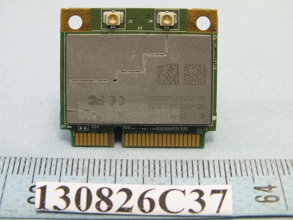
IXM-UNA-P3
Nov 21, 20133G Module
Equipment Class
PCB - PCS Licensed Transmitter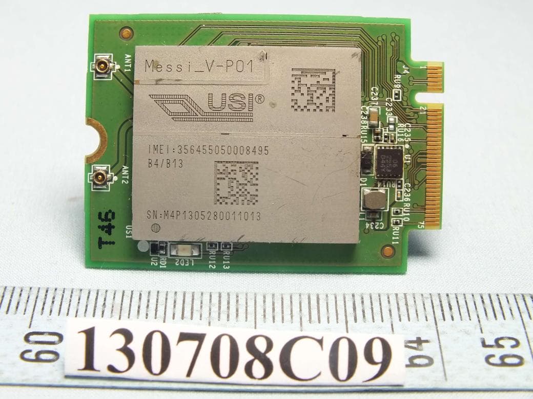
IXMMESSI-V
Sep 29, 2013LTE Module
Equipment Class
JBP - Part 15 Class B Computing Device Peripheral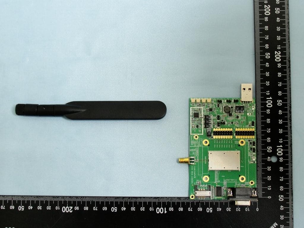
IXM-UNA850
Oct 01, 2012UNA 850 module
Equipment Class
PCB - PCS Licensed Transmitter
IXM-UNA900
Apr 19, 2012WWAN Module
Equipment Class
PCB - PCS Licensed Transmitter
IXMUGNAS-P3
Jul 28, 2011NETWORK ATTACHED STORAGE
Equipment Class
DTS - Digital Transmission System