IXMCF-B-AG-01802.11b WLAN CF Card
Universal Scientific Industrial Co., Ltd.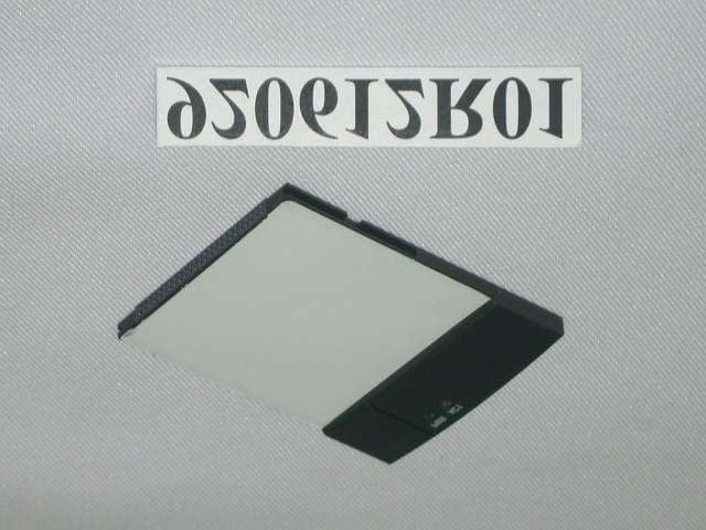
Click to zoom
Application Details
- Equipment Class
- DTS - Digital Transmission System
- Date of Grant
- Aug 17, 2003
- Application Purpose
- Original Equipment
- Date of Application
- Aug 17, 2003
- Equipment Note
- 802.11b WLAN CF Card
- Frequency Range
- 2412.00000000 - 2462.00000000
- Country
- Taiwan
Documents & Files
Document Text
Text extracted from the exhibit documents filed with the FCC. Open a document above to read the original.
Users Manual
Configure the Wireless Network To configure the wireless network in a PocketPC environment: 1.Tap Start Settings System tab. 2.Tap the USI WLAN CF Card icon to run the Wireless Networking Setting utility. 3. Select, add, or delete a profile: a. Select a profile from the drop-down menu, and tap OK to switch your station from one wireless network to another. b. Tap Add or Edit to add or edit the selected profile. c. Tap Delete to delete the selected profile. 4. Tap Next, and set the Network Name. USI WLAN CF Card 802.11b 2.4GHz Quick Start Guide 5. Tap Next, and configre your security settings. 6. Tap Next, and turn Power Management on or off. 7. Click finish. Finding Information • For more information, see the User's Guide on the CD that came with the card. • For the latest information, go to the USI website at www.usi.com.tw Information in this document is subject to change without notice. 2002 Universal Scientific Industrial Co.,Ltd.All rights reserved. Install the Driver To install the driver and utility on your Pocket PC from the software and documentation CD: 1. Using your sync cable or cradle, connect your Pocket PC to the computer. For additional information, see the documen- tation that came with your Pocket PC. 2. Insert the software and documentation CD into the drive on the computer. 3. Using Microsoft Windows Explorer or My Computer, navigate to x:\Setup, where x is the CD drive letter. 4. Double-click setup.exe. 5. Follow the instructions on the computer screen to finish the installation. 6. Insert the USI WLAN CFCard into the CF Card slot on your PocketPC. Reproduction in any manner whatso- ever without the written permission of USI is strictly forbidden. Federal Communications Commission (FCC) Requirements, Part 15 This equipment has been tested and found to comply with the limits for a class B digital device, pursuant to part 15 of the FCC Rules. These limits are designed to provide reasonable protection against harmful interference in a residential installation. This equipment generates, uses and can radiate radio frequency energy and, if not installed and used in accordance with the instructions, may cause harmful interference to radio communications. However, there is no guarantee that interference will not occur in a particular installation. If this equipment does cause harmful interference to radio or television reception, which can be determined by turning the equipment off and on, the user is encouraged to try to correct the interference by one or more of the following measures: ---Reorient or relocate the receiving antenna. ---Increase the separation between the equipment and receiver. ---Connect the equipment into an outlet on a circuit different from that to which the receiver is connected. ---Consult the dealer or an experienced radio/TV technician for help. This device complies with Part 15 of the FCC Rules. Operation is subject to the following two conditions: (1) This device may not cause harmful interference. (2) This device must accept any interference received, including interference that may cause undesired operation IMPORTANT NOTE FCC RF Radiation Exposure Statement: This equipment complies with FCC RF radiation exposure limits set forth for an uncontrolled environment. This device and its antenna must not be co-located or operating in conjunction with any other antenna or transmitter. Regulatory information / Disclaimers Installation and use of this Wireless LAN device must be in strict accordance with the instructions included in the user documentation provided with the product. Any changes or modifications (including the antennas) made to this device that are not expressly approved by the manufacturer may void the user’s authority to operate the equipment. The manufacturer is not responsible for any radio or television interference caused by unauthorized modification of this device, or the substitution of the connecting cables and equipment other than manufacturer specified. It is the responsibility of the user to correct any interference caused by such unauthorized modification, substitution or attachment. Manufacturer and its authorized resellers or distributors will assume no liability for any damage or violation of government regulations arising from failing to comply with these guidelines. Use on the supplied antenna. Unauthorized antenna, modification, or attachments could damage the transmitter and may violate FCC regulations.
Cover Letter(s)
Universal Scientific Industrial Co., Ltd. July 10,2003 Federal Communications Commission Authorization and Evaluation Division FCC ID: IXMCF-B-AG-01 Confidentiality Request Pursuant to Sections 0.457 and 0.459 of the Commission’s Rules, the Applicant hereby requests confidential treatment of information accompanying this Application as outlined below: 1. Schematic RF circuitry diagram 2. Functional block diagram 3. Operational Description The above materials contain trade secrets and proprietary information not customarily released to the public. The public disclosure of these matters might be harmful to the Applicant and provide unjustified benefits to its competitors. The Applicant understands that pursuant to Rule 0.457, disclosure of this Application and all accompanying documentation will not be made before the date of the Grant for this application. Sincerely, Johnson Ho / Section Manager Universal Scientific Industrial Co., Ltd.
Cover Letter(s)
From: [email protected] Sent: Monday, August 04, 2003 1:25 AM To: [email protected] Cc: [email protected]; [email protected]; [email protected] Subject: Subject: FW: Universal Scientific Industrial Co., Ltd., FCC ID:IXMCF-B- AG-01, AN03T3118 Hi Mike, Please find below for the answers for Q#1,-6,and 7. Q#1, please refer to the attached for the equipment spec for details. Q#2, the upper frequency for spurious emission test is to 24GHz, and because the reading of emissions are attenuated more than 20dB below the permissible limits or the field strength is too small to be measured, so they hadn't beeen recorded on the test report. Q#3, through checking and explain to USI, that now they can accept just do the product approval instead of modular approval, so please take off the modular request letter. Q#4, CF card can be taken as ITE accessory device and that's why FCC DOC logo is added.Also, attached please find a FCC Doc test report for reference. Q#5, the maintain distance and the modular installation have been deleted and please refer to the attached for the revised user manual. Q#6, please find the attached for the statement issued by USI, stating that this CF card can only be operated at the Ch. 1-11. Q#7, please refer to the attached for the revised confidential letter. Thank you and Best Regards, Jonson ----- Original Message ----- From: "Mike Kuo" <[email protected]> To: "Jonson Lee (E-mail)" <[email protected]>; "Eric (E-mail)" <[email protected]>; "Lucy (E-mail)" <[email protected]>; "Ting (E-mail)" <[email protected]> Sent: Tuesday, July 29, 2003 5:53 AM Subject: FW: Universal Scientific Industrial Co., Ltd., FCC ID:IXMCF-B-AG-01, AN03T3118 -----Original Message----- From: CERTADM Sent: Monday, July 28, 2003 2:49 PM To: '[email protected]' Subject: Universal Scientific Industrial Co., Ltd., FCC ID:IXMCF-B-AG-01, AN03T3118 Notice_content ------------- 15.247 portion : Question #1: The peak output power measurement was made with Narda detector. Based upon FCC recent instruction on the peak output measurement for WLAN device. Such instruction is given below: Output Power Measurements For all output power measurements using power meters, please assure that the probe video bandwidth is greater than the signal bandwidth. Otherwise measurement errors can result. We have noticed many instances, especially for DTS devices, where the output power measurement probe appeared to have a smaller video bandwidth than the signal bandwidth. When output power probes with sufficient bandwidth are not available to measure a particular signal than the alternate techniques, discussed in Joe Dichoso's "Unlicensed" TCB training material from May 2003, should be used. These techniques include spectrum analyzer channel power functions and power/bandwidth extrapolation. UNII devices have alternate procedures defined in Public Notice DA 02-2138. Remember for all power measurements please use the correct measurement detector peak or average corresponding to the appropriate limit. Please provide the specification of Narda Detector with the information to justify that such detector complied with FCC instruction. Otherwise, please provide output measurement to comply with FCC instruction. Question #2: What is the upper frequency investigated for radiated spurious emission tests above 1 GHz ? Question #3: The device submitted in this application is compact flash card with integral antenna with standard interface allows user to plug in this device in a typical notebook computer with CF interface. CF card with integral antenna is considered as finished product and it is not considered as module transmitter. This application will not be reviewed as transmitter module approval. Please confirm. Administrative review portion: Question #4: The proposed FCC ID label contains FCC DoC logo which indicates this devise is also complied with FCC DoC procedure. Please justify why this CF card is under the scope of FCC DoC procedure by referencing section 15.3(r ) of FCC rules. Question #5: There are two RF exposure statement provided in the user manual. One of RF exposure statement requires the end user to maintain 2.5cm separation distance and the other RF statement does not have such requirements. Please explain the intends for two RF exposure statements in the user manual. Question #6: Based upon the operational description, this CF card is capable of transmitting with 13 channels (EU) and 14 channels ( Japan ). Based upon recent FCC instructions, when the device is capable of transmitting beyond authorized frequency channel, the following information has to be confirmed by the manufacturer: User Selectable Frequencies by Country At this time, the FCC will not authorize transmitters that have the capability to allow the end user to choose various frequency bands that may be valid for other countries but are not in accordance with the frequency bands permitted by the FCC rules for use in the USA. This includes transmitters that use active or passive listening techniques on these non-USA frequencies. These transmitters must have these end user options disabled. Section 15.15(b) prohibits adjustments of any control by the user that will cause operation of a device in violation of the regulations. Accordingly, any proposal to allow the end user to choose extended channels on frequencies outside of an allowable frequency band in the USA is not acceptable. For example, a WLAN device operating according to Section 15.247 on channels 1-11 between 2.4 - 2.483.5 GHz must not have any user controls or software to allow the device to operate on channels 12 and 13 which are outside of the allowed USA band. This issue may be addressed in a future rulemaking. Based upon above instructions from FCC, please confirm in writing that this CF card will not have any user selectable function to enable this device operates beyond 2412-2462MHz. Question #7: Two items ( schematic and block diagram ) are listed in the request for confidenti…
Text truncated - open the document above for the full version.
Cover Letter(s)
Walsin Technology Corporation MULTILAYER CERAMIC ANTENNA RFANT Series 2.4 GHz ISM Band Working Frequency P/N: RFANT5220110A0T Customer :Universal Scientific Industrial Co., Ltd Approval No : Issue Date :June 18, 2003 Customer Approval : WALSIN Technology Corp. Authorized By : Page 1 of 13 AS_RFANT5220110A0T_USI_CF June-2003 Walsin Technology Corporation FEATURES ounted Devices with a small dimension of 5.2 x 2.0 x 1.1 mm 3 meet future miniaturization trend. design as PPLICATIONS N 2.4GHz wireless applications ESCRIPTION poration develops a new ceramic embedded antenna specified for 2.4 GHz ISM Band application, as his antenna has a rectangular ceramic body with a tiny dimension of 5.2x 2.0 x 1.1 mm 3 meet the future SMT automation and ONSTRUCTION Fig 1. Outline of 2.4GHz Antenna – RFANT5220110A0T F Surface M Embedded and LTCC (Low Temperature Co-fired Ceramic) technology is able to future integrate with system well as beautifying the housing of final product. High Stability in Temperature / Humidity Change A Bluetooth Wireless LA HormRF ISM band D Walsin Technology Cor shown in below “CONSTRUCTION”. Both of Wireless LAN IEEE 802.11b and Bluetooth TM typically located on this unlicensed frequency band which range covers from 2.4GHz to 2.4835GHz. To fulfil the friendly usage for antenna, this antenna has been designed to a typical 150MHz bandwidth through Walsin’s advanced LTCC (Low Temperature Co-fired Ceramic) technology and superior product design via 3D EM Simulation Skill. T miniaturization requirements on modern portable devices. C ig 2. Dimension 2.0 ±0.2 mm 1.15 ±0.10 mm 5.2 ± 0.2 m m 0.30 ± 0.15 m m 0.30 ± 0.15 m m WTC 2.0 ±0.2 mm 1.15 ±0.10 mm 5.2 ± 0.2 m m 0.30 ± 0.15 m m 0.30 ± 0.15 m m WTC W T C W T C Soldering terminal Identification mark Feeding W T C W T C Soldering terminal Identification mark Feeding Page 2 of 13 AS_RFANT5220110A0T_USI_CF June-2003 Walsin Technology Corporation SOLDER LAND PATTERN DESIGN Figure GROUND 6.4 1.0 1.0 4.4 2.0 Ground Soldering Pad 50 ΩTransmission Line Unit : mm GROUND 6.46.4 1.0 1.0 4.4 2.0 Ground Soldering Pad 50 ΩTransmission Line Unit : mm 1.01.0 To 50Ω RF I/O To 50Ω RF I/O ELECTRICAL CHARACTERISTICS Item Specification Working Frequency Range 2.4 GHz 2.5GHz Gain 2 dBi (Typical) VSWR 2 max. Polarization Linear Azimuth Beamwidth Omni-directional Impedance 50Ω Rated Power (max.) 3 Watts Maximum Input Power 5 Watts for 5 minutes Remark: The specification is defined based on the test board dimension as in below Page 3 of 13 AS_RFANT5220110A0T_USI_CF June-2003 Walsin Technology Corporation AS_RFANT5220110A0T_USI_CF June-2003 Antenna on Test Board ( FR4 Thickness 0.8mm) Empty Area Empty Area 18x9 mm Empty Area Empty Area 18x9 mm 50ΩFe line GROUND 30x18 mm ed ed 1mm 3.3mm 1.5mm WTC 2.5mm 18mm 50ΩFe line GROUND 30x18 mm 1mm 3.3mm 1.5mm WTCWTC 2.5mm 18mm Antenna S11 on Test Board Bandwidth >150MHz Bandwidth >150MHz Page 4 of 13 Walsin Technology Corporation RADIATION PATTERN RADIATION PATTERN Radiation Pattern and Gain were dependent on measurement board design. The specification of RFANT5220110A0T antenna was measured based on the PCB size and installation position as shown in the below figure Test Board Radiation Pattern and Gain were dependent on measurement board design. The specification of RFANT5220110A0T antenna was measured based on the PCB size and installation position as shown in the below figure Test Board Y Z WTC X Y Z WTC X Y Z WTC X Y Z WTC X Y Z WTC X Y Z WTC X GROUND 30x18 mm WT C X Y Z GROUND 30x18 mm WT C WT C X Y Z X Y Z Empty AreaEmpty Area z Y Vertical Vertical Horizontal Horizontal Y - Z Plane Average Gain= -3.22 dBi Peak Gain = 1.69 dBi Average Gain = -0.82 dBi Peak Gain= -5.42 dBi Average Gain=-8.98 dBi Y z Page 5 of 13 AS_RFANT5220110A0T_USI_CF June-2003 Walsin Technology Corporation Page 6 of 13 AS_RFANT5220110A0T_USI_CF June-2003 X Y X - Z Plane Average Gain= -3.24 dBi Peak Gain= -5.97 dBi Average Gain= -8.61dBi Peak Gain= 2.66 dBi Average Gain= -0.91 dBi X - Y Plane Average Gain= -3.12 dBi Peak Gain= -5.97 dBi Average Gain= -9.24dBi Peak Gain= 2.59 dBi Average Gain= -0.68 dBi z X z X X Y Walsin Technology Corporation APPLICATION INFORMATION (1). RFANT5220110A0T on Card-Bus Layout Proposal – (56mm x 43mm) Project Name: Hermes2 CF Card (TITAN) Measurement Condition: Housing included Antenna-2 Antenna-1 (2). VSWR and S11 Measurement Results: VSWR (2GHz to 3GHz) S11 (2GHz to 3GHz) Antenna-1 Antenna-2 1 2.4000GHz -14.095dB 2 2.4835GHz -11.737dB 3 2.3447GHz -9.3714dB 4 2.5135GHz -9.3631dB 5 2.5567GHz -6.7577dB 1 2.4000GHz -17.706dB 2 2.4835GHz -13.403dB 3 2.3417GHz -9.4271dB 4 2.5648GHz -9.9950dB 1 2.4000GHz 1.3062 2 2.4835GHz 1.5405 3 2.3417GHz 2.0523 4 2.5648GHz 1.9789 1 2.4000GHz 1.4886 2 2.4835GHz 1.6766 3 2.3447GHz 2.0228 4 2.5135GHz 2.0372 5 2.5567GHz 2.7238 Page 7 of 13 AS_RFANT5220110A0T_USI_CF June-2003 Walsin Technology Corporation Radiation Pattern at 2.45GHz: (1). Antenna-1: Z Y Z X X Y Z Y Z Y Z X Z X X Y X Y Peak Gain : -0.50dBi @ 145 deg Average Gain: -3.91dBi Peak Gain : -2.69dBi @ 20 deg Average Gain: -8.21dBi Peak Gain : -1.39dBi @ 120 deg Average Gain: -4.88dBi Peak Gain : -0.53dBi @ 245 deg Average Gain: -4.64dBi Peak Gain : -11.06dBi @ 85 deg Average Gain: -13.13dBi Peak Gain : +0.47dBi @ 300 deg Average Gain: -2.53dBi Page 8 of 13 AS_RFANT5220110A0T_USI_CF June-2003 Walsin Technology Corporation Page 9 of 13 AS_RFANT5220110A0T_USI_CF June-2003 (2). Antenna-2: Z Y Z X X Y Z Y Z Y Z X Z X X Y X Y g : i eg : i g : i g : i eg : i : i Peak Gain : -10.47dBi @ 255 d Average Gain-13.84dB Peak Gain : +0.69dBi @ 200 de Average Gain-3.69dB Peak Gain : -1.64dBi @ 190 de Average Gain-4.41dB Peak Gain : -1.43dBi @ 245 de Average Gain-4.51dB Peak Gain : +0.28dBi @ 40 deg Average Gain-3.64dB Peak Gain : -0.84dBi @ 345 d Average Gain-6.58dB Walsin Technology Corporation (3). General information The performance of embedded ceramic antenna could be sensitive influenced by customer's grounding area, PC board siz…
Text truncated - open the document above for the full version.
ID Label/Location Info
1 2 3 4 5 A A B B C C D D E E F F SOURCE ORGANIZATION TITLE: TAIWAN / COM MODEL NO DWG NO DESIGNER DATE SCALE: UNIT: mm USI P/N SHEET REV A1 APP BY DATE G NO DESCRIPTION DATE Unless otherwise Tolerance specified ± 1.0 1 A1 G 1 2 3 4 5 38mm 15 mm
RF Exposure Info
C&C Laboratory Co., Ltd. Report No: B30703002 FCC ID: IXMCF-B-AG-01 Date of Issue: July 18, 2003 Page 1 Total Pages: 1 in accordance with the requirements of FCC Report and Order: ET Docket 93-62, and OET Bulletin 65 Supplement C For Universal Scientific Industrial Co., Ltd. 802.11b WLAN CF Card Model: FCC ID: IXMCF-B-AG-01 Tr a d e N a m e : USI Prepared for Kuei Shan Hsiang,Tao Yuan Shien, Taiwan, R.O.C. Prepared by C&C LABORATORY, CO., LTD. Note: This report shall not be reproduced except in full, without the written approval of C&C Laboratory Co., Ltd. This document may be altered or revised by C&C Laboratory Co., Ltd. personnel only, and shall be noted in the revision section of the document. C&C Laboratory Co., Ltd. Report No: B30703002 FCC ID: IXMCF-B-AG-01 Date of Issue: July 18, 2003 Page 2 TABLE OF CONTENTS 1. TEST RESULT CERTIFICATION ................................................................................ 3 2. EUT DESCRIPTION ........................................................................................................ 3 3. REQUIREMENTS FOR COMPLIANCE TESTING DEFINED BY THE FCC ....... 5 4. DOSIMETRIC ASSESSMENT SYSTEM ...................................................................... 6 4.1 MEASUREMENT SYSTEM DIAGRAM............................................................................. 7 4.2 SYSTEM COMPONENTS .................................................................................................... 8 5. EVALUATION PROCEDURE...................................................................................... 10 5.1 DATA EVALUATION........................................................................................................ 10 5.2 SAR EVALUATION PROCEDURE .................................................................................. 11 6. MEASUREMENT UNCERTAINTY ............................................................................ 13 7. EXPOSURE LIMIT ........................................................................................................ 14 8. MEASUREMENT RESULTS ........................................................................................ 15 8.1 SYSTEM VALIDATION .................................................................................................... 15 8.2 TEST LIQUID CONFIRMATION ...................................................................................... 16 8.3 EUT TUNE-UP PROCEDURE ........................................................................................... 16 8.4 EUT SETUP PHOTOS ........................................................................................................ 18 8.5 SAR MEASUREMENT RESULT....................................................................................... 19 9. EUT PHOTOS ................................................................................................................. 20 10. EQUIPMENT LIST & CALIBRATION ...................................................................... 21 11. REFERENCES ................................................................................................................ 22 12. ATTACHMENT .............................................................................................................. 23 C&C Laboratory Co., Ltd. Report No: B30703002 FCC ID: IXMCF-B-AG-01 Date of Issue: July 18, 2003 Page 3 1. TEST RESULT CERTIFICATION Applicant: Equipment Under Test: 802.11b WLAN CF Card Trade Name: USI Model: FCC ID IXMCF-B-AG-01 Device Category: PORTABLE DEVICES Exposure Category: GENERAL POPULATION/UNCONTROLLED EXPOSURE Report Number: Date of Test: July 16, 2003 Test Sample is a: 802.11b WLAN CF Card Modulation Type: Direct Sequence Spread Spectrum Operating Mode: Maximum continuous output Tx Frequency: 2412 ~ 2462 MHz Max. O/P Power: 15.9dBm (2462 MHz) (Conducted) Max. SAR (1g): 0.124mW/g (2437MHz ) Application Type: Certification FCC Rule part(s): § 15.247 Laptop: COMPAQ Part No: SERIES2150 Serial No.: 1V31LDLZ3407 This wireless portable device has been shown to be capable of compliance for localized specific absorption rate (SAR) for uncontrolled environment/general population exposure limits specified in ANSI/IEEE Std. C95.1-1999 and had been tested in accordance with the measurement procedures specified in FCC OET 65 Supplement C (released on 6/29/2001 - see Test Report). I attest to accuracy of the data. All measurements reported herein were performed by me or were made under my supervision and are correct to the best of my knowledge and belief. I assume full responsibility for completeness of these measurements and vouch for the qualifications of all persons taking them. Approved By Reviewed By Jonson Lee / Director Chris Hsieh / Engineer C&C Laboratory Co., Ltd. C&C Laboratory Co., Ltd. C&C Laboratory Co., Ltd. Report No: B30703002 FCC ID: IXMCF-B-AG-01 Date of Issue: July 18, 2003 Page 4 2. EUT DESCRIPTION Applicant: Equipment Under Test: 802.11b WLAN CF Card Trade Name: USI Model: FCC ID IXMCF-B-AG-01 Device Category: PORTABLE DEVICES Exposure Category: GENERAL POPULATION/UNCONTROLLED EXPOSURE Report Number: Date of Test: July 16, 2003 Test Sample is a: Notebook with 802.11b WLAN Modulation Type: Direct Sequence Spread Spectrum Operating Mode: Maximum continuous output Tx Frequency: 2412 ~ 2462 MHz Max. O/P Power: 15.9 dBm (2462MHz) (Conducted) Max. SAR (1g): 0.124mW/g (2437MHz) Application Type: Certification FCC Rule part(s): § 15.247 Laptop: COMPAQ Part No: SERIES2150 Serial No.: 1V31LDLZ3407 Notes: 1 Specific Absorption Rate (SAR) is a measure of the rate of energy absorption due to exposure to an RF transmitting source (wireless portable device). 2 EEE/ANSI Std. C95.1-1999 limits are used to determine compliance with FCC ET Docket 93-62 C&C Laboratory Co., Ltd. Report No: B30703002 FCC ID: IXMCF-B-AG-01 Date of Issue: July 18, 2003 Page 5 3. REQUIREMENTS FOR COMPLIANCE TESTING DEFINED BY THE FCC The US Federal Communications Commission has releas…
Text truncated - open the document above for the full version.
RF Exposure Info
Date/Time: 07/16/03 11:16:38 Test Laboratory: The name of your organization File Name: D2450V2 SN 728.da4 D2450V2 SN 728 DUT: Dipole 2450 MHz; Type: D2450V2; Serial: D2450V2 - SN:728 Program: System Performance Check at 2450MHz Communication System: CW2450; Frequency: 2450 MHz;Duty Cycle: 1:1 Medium: HSL2450 (σ = 1.746 mho/m, ε r = 38.362, ρ = 1000 kg/m 3 ) Air Temperature 25.8 deg C ; Liquid Temperature 25.3 deg C Phantom section: Flat Section DASY4 Configuration: z Probe: ET3DV6 - SN1762; ConvF(5.1, 5.1, 5.1); Calibrated: 3/31/2003 z Sensor-Surface: 4mm (Mechanical And Optical Surface Detection) Sensor-Surface: 0mm (Fix Surface) z Electronics: DAE3 Sn558; Calibrated: 3/7/2003 z Phantom: SAM 34; Type: SAM V4.0; Serial: TP-1150 z Measurement SW: DASY4, V4.1 Build 47; Postprocessing SW: SEMCAD, V1.6 Build 115 Pin=250mW,d=10mm/Area Scan (6x6x1): Measurement grid: dx=15mm, dy=15mm Reference Value = 97.6 V/m Power Drift = -0.02 dB Maximum value of SAR = 10.8 mW/g Pin=250mW,d=10mm/Zoom Scan (5x5x7)/Cube 0: Measurement grid: dx=7.5mm, dy=7.5mm, dz=5mm Peak SAR (extrapolated) = 27.8 W/kg SAR(1 g) = 13.7 mW/g; SAR(10 g) = 6.34 mW/g Reference Value = 97.6 V/m Power Drift = -0.02 dB Maximum value of SAR = 15.1 mW/g Pin=250mW,d=10mm/Z Scan (1x1x21): Measurement grid: dx=20mm, dy=20mm, dz=5mm Reference Value = 97.6 V/m Power Drift = -0.01 dB Maximum value of SAR = 12.7 mW/g Page1 0 dB = 15.1mW/g Page2
RF Exposure Info
Date/Time: 07/16/03 12:29:00 Test Laboratory: The name of your organization File Name: cf-0mm.da4 cf-0mm DUT: 802.11b WLAN cf card; Type: CF-B-AG-01; Serial: FCC ID:IXMCF-B-AG-01 Program: touch Communication System: 802.11b WLAN cf card; Frequency: 2412 MHz;Duty Cycle: 1:1 Medium: BSL2450 (σ = 1.927 mho/m, ε r = 51.017, ρ = 1000 kg/m 3 ) Air Temperature 25.9 deg C ; Liquid Temperature 25.9 deg C Phantom section: Flat Section DASY4 Configuration: z Probe: ET3DV6 - SN1762; ConvF(4.6, 4.6, 4.6); Calibrated: 3/31/2003 z Sensor-Surface: 4mm (Mechanical And Optical Surface Detection) Sensor-Surface: 0mm (Fix Surface) z Electronics: DAE3 Sn558; Calibrated: 3/7/2003 z Phantom: SAM 12; Type: SAM V4.0; Serial: TP-1271 z Measurement SW: DASY4, V4.1 Build 47; Postprocessing SW: SEMCAD, V1.6 Build 115 low/Area Scan (6x6x1): Measurement grid: dx=15mm, dy=15mm Reference Value = 3.94 V/m Power Drift = 0.004 dB Maximum value of SAR = 0.105 mW/g low/Zoom Scan (5x5x7)/Cube 0: Measurement grid: dx=7.5mm, dy=7.5mm, dz=5mm Peak SAR (extrapolated) = 0.234 W/kg SAR(1 g) = 0.104 mW/g; SAR(10 g) = 0.0498 mW/g Reference Value = 3.94 V/m Power Drift = 0.004 dB Maximum value of SAR = 0.112 mW/g low/Z Scan (1x1x21): Measurement grid: dx=20mm, dy=20mm, dz=5mm Reference Value = 3.94 V/m Power Drift = -0.05 dB Maximum value of SAR = 0.0791 mW/g Page1 0 dB = 0.112mW/g Page2 Date/Time: 07/16/03 12:52:53 Test Laboratory: The name of your organization File Name: cf-0mm.da4 cf-0mm DUT: 802.11b WLAN cf card; Type: CF-B-AG-01; Serial: FCC ID:IXMCF-B-AG-01 Program: touch Communication System: 802.11b WLAN cf card; Frequency: 2437 MHz;Duty Cycle: 1:1 Medium: BSL2450 (σ = 1.927 mho/m, ε r = 51.017, ρ = 1000 kg/m 3 ) Air Temperature 25.9 deg C ; Liquid Temperature 25.9 deg C Phantom section: Flat Section DASY4 Configuration: z Probe: ET3DV6 - SN1762; ConvF(4.6, 4.6, 4.6); Calibrated: 3/31/2003 z Sensor-Surface: 4mm (Mechanical And Optical Surface Detection) Sensor-Surface: 0mm (Fix Surface) z Electronics: DAE3 Sn558; Calibrated: 3/7/2003 z Phantom: SAM 12; Type: SAM V4.0; Serial: TP-1271 z Measurement SW: DASY4, V4.1 Build 47; Postprocessing SW: SEMCAD, V1.6 Build 115 mid/Area Scan (6x6x1): Measurement grid: dx=15mm, dy=15mm Reference Value = 3.94 V/m Power Drift = 0.2 dB Maximum value of SAR = 0.13 mW/g mid/Zoom Scan (5x5x7)/Cube 0: Measurement grid: dx=7.5mm, dy=7.5mm, dz=5mm Peak SAR (extrapolated) = 0.282 W/kg SAR(1 g) = 0.124 mW/g; SAR(10 g) = 0.0591 mW/g Reference Value = 3.94 V/m Power Drift = 0.2 dB Maximum value of SAR = 0.131 mW/g mid/Z Scan (1x1x21): Measurement grid: dx=20mm, dy=20mm, dz=5mm Reference Value = 3.94 V/m Power Drift = 0.2 dB Maximum value of SAR = 0.0966 mW/g Page1 0 dB = 0.131mW/g Page2 Date/Time: 07/16/03 13:23:15 Test Laboratory: The name of your organization File Name: cf-0mm.da4 cf-0mm DUT: 802.11b WLAN cf card; Type: CF-B-AG-01; Serial: FCC ID:IXMCF-B-AG-01 Program: touch Communication System: 802.11b WLAN cf card; Frequency: 2462 MHz;Duty Cycle: 1:1 Medium: BSL2450 (σ = 1.927 mho/m, ε r = 51.017, ρ = 1000 kg/m 3 ) Air Temperature 25.8 deg C ; Liquid Temperature 25.8 deg C Phantom section: Flat Section DASY4 Configuration: z Probe: ET3DV6 - SN1762; ConvF(4.6, 4.6, 4.6); Calibrated: 3/31/2003 z Sensor-Surface: 4mm (Mechanical And Optical Surface Detection) Sensor-Surface: 0mm (Fix Surface) z Electronics: DAE3 Sn558; Calibrated: 3/7/2003 z Phantom: SAM 12; Type: SAM V4.0; Serial: TP-1271 z Measurement SW: DASY4, V4.1 Build 47; Postprocessing SW: SEMCAD, V1.6 Build 115 High/Area Scan (6x6x1): Measurement grid: dx=15mm, dy=15mm Reference Value = 4.23 V/m Power Drift = 0.02 dB Maximum value of SAR = 0.113 mW/g High/Zoom Scan (5x5x7)/Cube 0: Measurement grid: dx=7.5mm, dy=7.5mm, dz=5mm Peak SAR (extrapolated) = 0.277 W/kg SAR(1 g) = 0.122 mW/g; SAR(10 g) = 0.0579 mW/g Reference Value = 4.23 V/m Power Drift = 0.02 dB Maximum value of SAR = 0.127 mW/g High/Z Scan (1x1x21): Measurement grid: dx=20mm, dy=20mm, dz=5mm Reference Value = 4.23 V/m Power Drift = -0.2 dB Maximum value of SAR = 0.0955 mW/g Page1 0 dB = 0.127mW/g Page2 Date/Time: 07/16/03 14:30:05 Test Laboratory: The name of your organization File Name: cf-15mm.da4 cf-15mm DUT: 802.11b WLAN cf card; Type: CF-B-AG-01; Serial: FCC ID:IXMCF-B-AG-01 Program: 15mm Communication System: 802.11b WLAN cf card; Frequency: 2412 MHz;Duty Cycle: 1:1 Medium: BSL2450 (σ = 1.927 mho/m, ε r = 51.017, ρ = 1000 kg/m 3 ) Air Temperature 25.6 deg C ; Liquid Temperature 25.5 deg C Phantom section: Flat Section DASY4 Configuration: z Probe: ET3DV6 - SN1762; ConvF(4.6, 4.6, 4.6); Calibrated: 3/31/2003 z Sensor-Surface: 4mm (Mechanical And Optical Surface Detection) Sensor-Surface: 0mm (Fix Surface) z Electronics: DAE3 Sn558; Calibrated: 3/7/2003 z Phantom: SAM 12; Type: SAM V4.0; Serial: TP-1271 z Measurement SW: DASY4, V4.1 Build 47; Postprocessing SW: SEMCAD, V1.6 Build 115 low/Area Scan (5x4x1): Measurement grid: dx=15mm, dy=15mm R…
Text truncated - open the document above for the full version.
Contact Information
Applicant
Martin Shih(Section Manager)
Test Firm
Compliance Certification Services Inc.Kurt Chen
Technical Specifications
| # | Rule Parts | Frequency Range | Power Output |
|---|---|---|---|
| 1 | 15C | 2.41 GHz - 2.46 GHz | 38.90 mW |
Other Applications from Universal Scientific Industrial Co., Ltd.
IXM-UNA-P3
Nov 21, 20133G Module
Equipment Class
PCB - PCS Licensed Transmitter
IXMMESSI-V
Sep 29, 2013LTE Module
Equipment Class
JBP - Part 15 Class B Computing Device Peripheral
IXM-UNA850
Oct 01, 2012UNA 850 module
Equipment Class
PCB - PCS Licensed Transmitter
IXM-UNA900
Apr 19, 2012WWAN Module
Equipment Class
PCB - PCS Licensed Transmitter
IXMUGNAS-P3
Jul 28, 2011NETWORK ATTACHED STORAGE
Equipment Class
DTS - Digital Transmission System