IXMCF-B-AG-02802.11b WLAN Compact Flash Module
Universal Scientific Industrial Co., Ltd.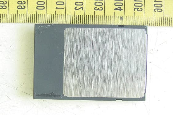
Click to zoom
Application Details
- Equipment Class
- DTS - Digital Transmission System
- Date of Grant
- Mar 11, 2004
- Application Purpose
- Original Equipment
- Date of Application
- Mar 11, 2004
- Equipment Note
- 802.11b WLAN Compact Flash Module
- Frequency Range
- 2412.00000000 - 2462.00000000
- Country
- Taiwan
Documents & Files
Document Text
Text extracted from the exhibit documents filed with the FCC. Open a document above to read the original.
Users Manual
WLAN 802.11b Compact Flash Card Users’ Manual v 1.2 Copyright© 2004 by separated owners. All Rights Reserved. Contents 1. Introduction........................................................................3 1.1 Features.................................................................................3 2. Install and Configure a Wireless Network.................................5 2.1 Preparation............................................................................5 2.2 Install Drivers and Utilities From a CD..........................................5 2.3 Configure the Wireless Network on Your Device............................7 3. Using the Client Manager Utility............................................18 3.1 Installing the Client Manager.....................................................18 3.2 Taskbar Icon Status................................................................18 3.3 Using the Client Manager.........................................................19 4. Specifications....................................................................21 4.1 Physical Specifications ...........................................................21 4.2 Power Characteristics..............................................................21 4.3 Networking Characteristics................................................... ...21 4.4 Radio Characteristics...............................................................22 5. Basic Troubleshooting........................................................24 2 1. Introduction A WLAN is a local area network that uses radio frequencies to transmit and receive data between computers or other network devices. WLANs can be independent networks, which use small or temporary peer-to-peer configurations, or infrastructure networks. The Compact Flash card (CF card) allows devices running the Microsoft ® Pocket PC operating system to connect to a Wi-Fi IEEE 802.11b WLAN or communicate directly with other devices connected to a WLAN. This product is a 802.11b 11 Mbps wireless network adapter that provides CF+ host interface with Type-I mechanical design. The CF card is designed to meet the mobility, performance, security, interoperability, management, and reliability requirements of the IEEE 802.11b high data rate standard . The CF card provides PDA or handheld PC users highly mobility from cell-to-cell roaming. With a CF-to PCMCIA adapter, users can easily implement this WLAN device under most \Windows platforms. The product contains two ceramic antennas that provide diversity switch, which support robust and smooth data connection under multi-path (office) environment. New features such as WOL (Wake on LAN) and 802.11d are supported for new applications and requirements. In addition to WEP, WPA and TKIP are supported to provide the security on your network. 1.1 Features • Compact Flash form factor fits devices with Compact Flash Type I extended card slots. • Functions with devices that are running the Pocket PC operating system and that are equipped with Compact Flash Type I extended card slots. • Compliant with 11 Mbps 802.11b high-speed specification. • Data rate of 11/5.5/2/1 Mbps; includes automatic fallback in a noisy environment. 3 • Power management to keep low power consumption and extend battery life of Host system. • Small size and premium ID design which is suitable for PDA and handled device. Enables you to be fully mobile. • Can be operated with IEEE 802.11b compliant equipment. • User-friendly client manager utility. • Supports 64- and 128-bit Wired Equivalent Privacy (WEP). • Direct Sequence Spread Spectrum (DSSS) technology provides robust, interference-resistant, and secure wireless connection. • Wireless connection without the hassles and cost of cabling. • Greater flexibility to locate or move a networked device. • Support 802.11d for universal regulation • The CF card has two LED indicators: Transmit/receive and power on/off. • Support Windows XP/ME/2000/98/CE 3.0/Pocket PC 2002,2003 4 2. Install and Configure the Wireless Network 2.1 Preparation Before the installation, please check the contents for: • A 802.11b WLAN CF card • A software driver CD for your CF card • A quick install guide. To install the CF card, you need the items: • A device equipped with CF Type I extended card slots • A sync cable that comes with your PDA • A computer with a CD or DVD drive 2.2 Install Drivers and Utilities From a CD Please follow the steps to install the drivers and utilities: Step 1: Connect the sync cable to either a serial or a USB connector on the computer, and connect the other end of the cable to the device. When a connection exists between the computer and the device, you can transfer data and synchronize the information on your computer with the information on your device. Step 2: Insert the software driver into the CD drive on the computer. Step 3: The driver will auto-run. Please click Install Driver when you see the screen.(Note: Please go to g:/WinCE/setup.exe to install the driver. Drive g is your CD or DVD driver.) Step 4: Follow the instructions on your computer screen to finish the installation. 5 Step 5: Insert the CF card into your device. You can access the client manager utility from the taskbar on the Today screen. 2.3 Configure the Wireless Network on Your Device After you insert the CF card into the host, please follow the steps to configure the wireless network. 1. Click the Start ÆSettingsÆSystem, and then click the WLAN Network icon to run the Wireless Networking Setting utility. Note: For WinCE3.0, Windows CE4.0, Pocket PC 2002, and Pocket PC 2003 users, the configuration procedure is the same. 6 ¾ (I) Select a profile and click OK to switch from one wireless network to another. ¾ (II) Click Add or Edit to add or edit the selected profile. ¾ (III) Click Delete to delete the selected profile. (I) Select a Profile Select a configuration profile to switch your station from one wireless network to another. [NOTE]: Before you can s…
Text truncated - open the document above for the full version.
Cover Letter(s)
1 Mike Kuo From: iris Sent: March102004Wednesday 1:23 AM To: Mike Kuo Subject: Re: Universal Scientific Industrial Co., Ltd., FCC ID:IXMCF-B-AG-02, AN04T3725 CF-B-AG-02-manual -v1.pdf Hi Mike, Please see the attachment. We have already revise the user manual. If you have any other question, please advise us ASAP. Because we are very urgent for this case (include Canada). Best Regards, Iris Lin ----- Original Message ----- From: "Mike Kuo" <[email protected]> To: "ETC/Iris (E-mail)" ; "Liou, S. S. (E-mail)" Cc: "Will Yauo (E-mail)" Sent: Tuesday, March 09, 2004 2:18 AM Subject: FW: Universal Scientific Industrial Co., Ltd., FCC ID:IXMCF-B-AG-02, AN04T3725 > > > -----Original Message----- > From: CERTADM > Sent: Monday, March 08, 2004 10:12 AM > To: Mike Kuo > Subject: Universal Scientific Industrial Co., Ltd., FCC ID:IXMCF-B-AG-02, > AN04T3725 > > > Notice_content > ------------- > Question #1: In the request for modular approval letter, it mentioned this > device will be used as mobile device per section 2.1091 of FCC rules. In > the page 22 of user manual, in the caution statement, it requires to have > this device and its antenna to be installed to provide 20 cm separation > distance but manual also indicate this device complies with section > 2.1093(d)(2) ( portable device ) of RF exposure compliance. In the > operational description and user manual, mentioned this CF card is suitable > for handheld device like PDA or tablet PC. > > The intended usage of this CF card with external antennas are designed to be > used in both Portable/ section 2.1093 and Mobile / section 2.1091 of FCC > rules. The antenna cable length of two proposed antennas are less than 20 > cm. If this device is used for handheld product or laptop/tablet device, > the 20 cm separation distance can not be maintained. If this device is used > by access point or wireless router, due the design of access point and 2 > router, 20 cm separation distance can be maintained. > > Based upon above assessment, please confirm the following : > > a. This application will be reviewed as limited modular approval to be used > in access point, wireless router or desktop computer where the 20 cm > separation distance can be maintained between transmitting antenna to the > body of end user. Use in handheld device or notebook computer are > prohibited. This device can only be installed by OEM installer, user > installation is prohibited. > > B. if this device is going to be sold to handheld device or notebook > computer, the antenna needs to be installed inside typical PDA or notebook > computer to be tested for radiated spurious emission and restricted band > edge. The minimum separation distance between the transmitting antennas to > the body of end user will be at least 2.5 cm separation distance. Due to > the output power is below 120/2.4GHz=50mW, with at least 2.5 cm separation > distance, SAR evaluation is not required. > > C. if this device is going to be used as mobile device per section 2.1093 of > rules, please delete the statement in page 22 of user manual where > indicating that this device complies with 2.1091(d)(2) of RF exposure > compliance. In addition, please remove all device usages for handheld > device or notebook computer. > > Best Regards > > Mike Kuo > The items indicated above must be submitted before processing can continue > on the above referenced application. Failure to provide the requested > information within 30 days of the original e-mail date may result in > application dismissal and forfeiture of the filing fee. Also, please note > that partial responses increase processing time and should not be submitted. > Any questions about the content of this correspondence should be directed to > the e-mail address listed below the name of the sender.
External Photos
ETC Report No. : ET93R-02-063-04 FCC ID.:IXMCF-B-AG-02 Rev. No 1.0 CONSTRUCTED PHOTOS of EUT Front View of EUT Rear View of EUT
Internal Photos
ETC Report No. : ET93R-02-063-04 FCC ID.:IXMCF-B-AG-02 Rev. No 1.0 CONSTRUCTED PHOTOS of EUT Internal View of EUT ETC Report No. : ET93R-02-063-04 FCC ID.:IXMCF-B-AG-02 Rev. No 1.0 CONSTRUCTED PHOTOS of EUT Component View of Main PCB Component View of Main PCB ETC Report No. : ET93R-02-063-04 FCC ID.:IXMCF-B-AG-02 Rev. No 1.0 CONSTRUCTED PHOTOS of EUT Solder View of Main PCB Front View ofTransmission track type antenna (KD02961-L05X) ETC Report No. : ET93R-02-063-04 FCC ID.:IXMCF-B-AG-02 Rev. No 1.0 CONSTRUCTED PHOTOS of EUT Rear View ofTransmission track type antenna (KD02961-L05X) Front View ofHelical antenna (CA05951-738X) ETC Report No. : ET93R-02-063-04 FCC ID.:IXMCF-B-AG-02 Rev. No 1.0 CONSTRUCTED PHOTOS of EUT Rear View ofHelical antenna (CA05951-738X)
RF Exposure Info
FCC ID: IXMPCF-B-AG-02 RF Exposure Evaluation of E.U.T. : 802.11b WLAN CompactFlash Module FCC ID. : IXMPCF-B-AG-02 MODEL : CF-B-AG-02 for APPLICANT : Universal Scientific Industrial Co., Ltd. ADDRESS : 141, Lane 351, Taiping Road, Sec. 1, Tsao Tuen, Nan-Tou, Taiwan Prepared by ELECTRONICS TESTING CENTER, TAIWAN NO. 34, LIN 5, DING FU TSUN, LINKOU HSIANG, TAIPEI HSIEN, TAIWAN, R.O.C. Tel:(02)26023052 Fax:(02)26010910 http://www.etc.org.tw ; e-mail: [email protected] Report Number : ET93R-02-063-04 FCC ID: IXMPCF-B-AG-02 Product Information: Type of EUT: 802.11b WLAN CompactFlash Module FCC ID: IXMPCF-B-AG-02 Manufacturer: Universal Scientific Industrial Co., Ltd. Model: CF-B-AG-02 Description: The 802.11b WLAN CompactFlash Module designed with a transmitting method of direct sequence spread spectrum is for local area network operation, which operates at 2.4 GHz ISM band and data rate up to 11 Mbps. Maximum conducted output power (measured): 14.0 dBm or 27.54 mW The following table lists the provided authorized antennas: Antenna Gain Model Antenna Type (dBi) Numeric KD02961-L05X /4Transmission track type –0.80 0.83 CA05951-738X /4Helical antenna –1.25 0.74 Below is an example of the RF Exposure Statement: CAUTION: To maintain compliance with FCC’s RF exposure guidelines, this equipment should be installed and operated with minimum distance 20cm between the radiator and your body. Use on the supplied antenna. Unauthorized antenna, modification, or attachments could damage the transmitter and may violate FCC regulations. FCC ID: IXMPCF-B-AG-02 Relative Requirement for Compliance According to section 1.1310 of FCC 47 CFR Part 1, limits for maximum permissible exposure (MPE) are as following: TABLE 1 – LIMITS FOR MAXIMUN PERMISSIBLE EXPOSURE (MPE) Frequency Range (MHz) Electric Field Strength (V/m) Magnetic Field Strength (A/m) Power Density (mW/cm 2 ) Averaging Time (minutes) (A) Limits for Occupational/Controlled Exposures 0.3-3.0 .................. 614 1.63 *(100) 6 3-30 ..................... 1842/f 4.89/f *(900/f 2 ) 6 30-300 .................. 61.4 0.163 1.0 6 300-1500 ............... ...................... ...................... f/300 6 1500-100,000 ......... ...................... ...................... 5 6 (B) Limits for General Population/Uncontrolled Exposure 0.3-1.34 ............... 614 1.63 *(100) 30 1.34-30 ............... 824/f 2.19/f *(180/f2) 30 30-300 .................. 27.5 0.073 0.2 30 300-1500 ............... ...................... ...................... f/1500 30 1500-100,000 ......... ...................... ...................... 1.0 30 f = frequency in MHz * = Plane-wave equivalent power density NOTE 1 TO TABLE 1: Occupational/controlled limits apply in situations in which persons are exposed as a consequence of their employment provided those persons are fully aware of the potential for exposure and can exercise control over their exposure. Limits for occupational/controlled exposure also apply in situations when an individual is transient through a location where occupational / controlled limits apply provided he or she is made aware of the potential for exposure. NOTE 2 TO TABLE 1: General population/uncontrolled exposures apply in situations in which the general public may be exposed, or in which persons that are exposed as a consequence of their employment may not be fully aware of the potential for exposure or can not exercise control over their exposure. FCC ID: IXMPCF-B-AG-02 RF Exposure Calculations: The following information provides the minimum separation distance for the highest gain antenna provided. This calculation is based on the highest EIRP possible from the system, considering maximum power and antenna gain, and considering a 1.0 mW/cm 2 uncontrolled exposure limit. The formula shown in OET Bulletin 65 is used in the calculation. Equation from page 19 of OET Bulletin 65, Edition 97-01 is: S= PG / 4R 2 where: S = power density (in appropriate units, e.g. mW/cm 2 ) P = power input to the antenna (in appropriate units, e.g., mW) G = power gain of the antenna in the direction of interest relative to an isotropic radiator R = distance to the center of radiation of the antenna (appropriate units, e.g., cm) hence R= PG / 4S) 1/2 For our device P = 27.54 mW G = 0.83 S = Exposure limit = 1.0 mW/cm 2 R = ((27.54 * 0.83) / (4**1.0)) 1/2 = 1.35 cm For complying the FCC limits for general population/uncontrolled exposure, the minimum MPE distance is 1.35 cm. This means that according to OET Bulletin 65 (Edition 97-01), Supplement C (Edition 01-01), the equipment fulfills the requirements on power density for general population/uncontrolled exposure and therefore fulfills the requirements of 47 CFR Part 15.247 (b)(5).
Test Report
Rev. No 2.0 FCC Part 15 EMI TEST REPORT of E.U.T. : 802.11b WLAN CompactFlash Module FCC ID. : IXMPCF-B-AG-02 MODEL : CF-B-AG-02 for APPLICANT: Universal Scientific Industrial Co., Ltd. ADDRESS: 141, Lane 351, Taiping Road, Sec. 1, Tsao Tuen, Nan-Tou, Taiwan Test Performed by ELECTRONICS TESTING CENTER, TAIWAN NO. 34, LIN 5, DING FU TSUN, LINKOU HSIANG TAIPEI HSIEN, TAIWAN, R.O.C. Tel : (02)26023052 Fax : (02)26010910 http://www.etc.org.tw ; e-mail:[email protected] Report Number : ET93R-02-063-04 ETC Report No. : ET9 3R-02-063-04FCC ID.: IXMCF-B-AG-02 Rev. No 1.0 Table of ContentsPage 1 GENERAL INFORMATION........................................................................................................1 1.1 Product Description........................................................................................................................1 1.2 Characteristics of Device.................................................................................................................1 1.3 Test Methodology...........................................................................................................................1 1.4 Test Facility....................................................................................................................................1 2 PROVISIONS APPLICABLE........................................................................................................2 2.1 Definition........................................................................................................................................2 2.2 Requirement for Compliance...........................................................................................................3 2.3 Restricted Bands of Operation.........................................................................................................5 2.4 Labeling Requirement......................................................................................................................5 2.5 User Information.............................................................................................................................6 3. SYSTEM TEST CONFIGURATION............................................................................................7 3.1 Justification.....................................................................................................................................7 3.2 Devices for Tested System..............................................................................................................7 4 RADIATED EMISSION MEASUREMENT...............................................................................8 4.1 Applicable Standard........................................................................................................................8 4.2 Measurement Procedure.................................................................................................................8 4.3 Measuring Instrument....................................................................................................................10 4.4 Radiated Emission Data.................................................................................................................11 4.4.1 RF Portion.............................................................................................................................. 11 4.4.2 Radiated Eimssion of Restricted bands...................................................................................... 17 4.4.3 Other Emission........................................................................................................................ 19 4.5 Field Strength Calculation..............................................................................................................20 4.6 Photos of Radiation Measuring Setup............................................................................................21 5 CONDUCTED EMISSION MEASUREMENT.........................................................................23 5.1 Standard Applicable......................................................................................................................23 5.2 Measurement Procedure...............................................................................................................23 5.3 Conducted Emission Data.............................................................................................................24 5.4 Result Data Calculation.................................................................................................................27 5.5 Conducted Measurement Equipment.............................................................................................28 5.6 Photos of Conduction Measuring Setup.........................................................................................29 6 ANTENNA REQUIREMENT.....................................................................................................31 6.1 Standard Applicable......................................................................................................................31 6.2 Antenna Construction and Directional Gain....................................................................................31 7 EMISSION BANDWIDTH MEASUREMENT..........................................................................32 ETC Report No. : ET9 3R-02-063-04FCC ID.: IXMCF-B-AG-02 Rev. No 1.0 7.1 Standard Applicable......................................................................................................................32 7.2 Measurement Procedure...............................................................................................................32 7.3 Measurement Equipment...............................................................................................................32 7.4 Measurement Data..........................................................................................…
Text truncated - open the document above for the full version.
Test Setup Photos
ETC Report No. : ET93R-02-063-04 FCC ID.:IXMCF-B-AG-02 Rev. No 1.0 Photos of Radiation Measuring Setup A. Transmission track type antenna (KD02961-L05X) @11Mbps ETC Report No. : ET93R-02-063-04 FCC ID.:IXMCF-B-AG-02 Rev. No 1.0 B. Helical antenna(CA05951-738X) @11Mbps
Contact Information
Applicant
Martin Shih(Section Manager)
Test Firm
Electronics Testing Center, TaiwanWin-Po Tsai
Technical Specifications
| # | Rule Parts | Frequency Range | Power Output |
|---|---|---|---|
| 1 | 15C | 2.41 GHz - 2.46 GHz | 27.50 mW |
Other Applications from Universal Scientific Industrial Co., Ltd.
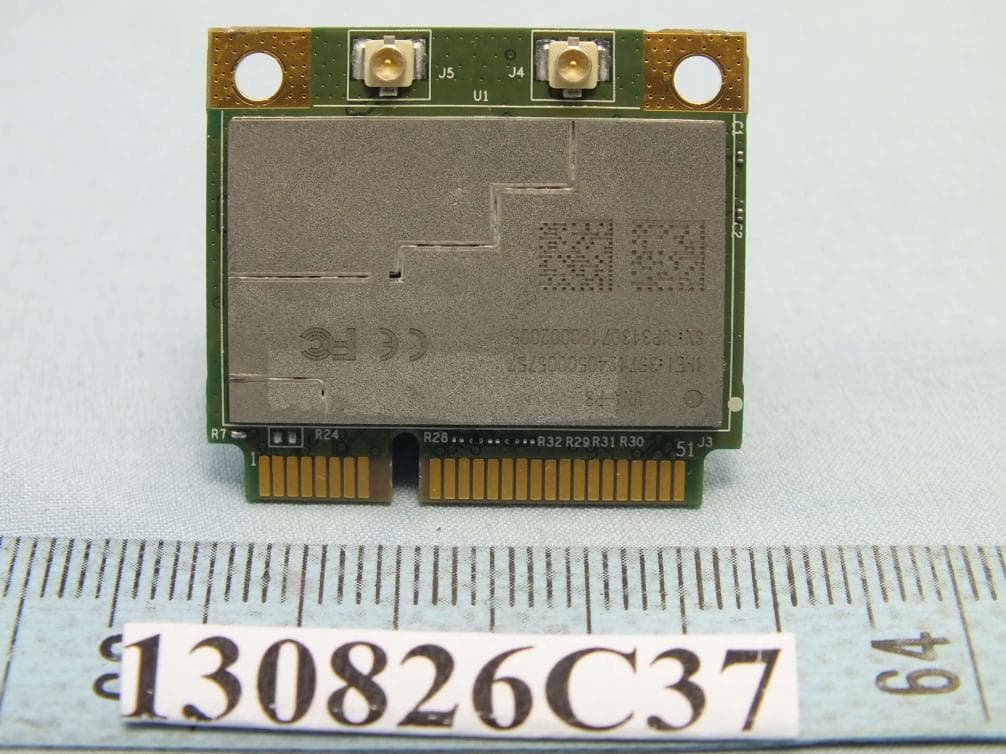
IXM-UNA-P3
Nov 21, 20133G Module
Equipment Class
PCB - PCS Licensed Transmitter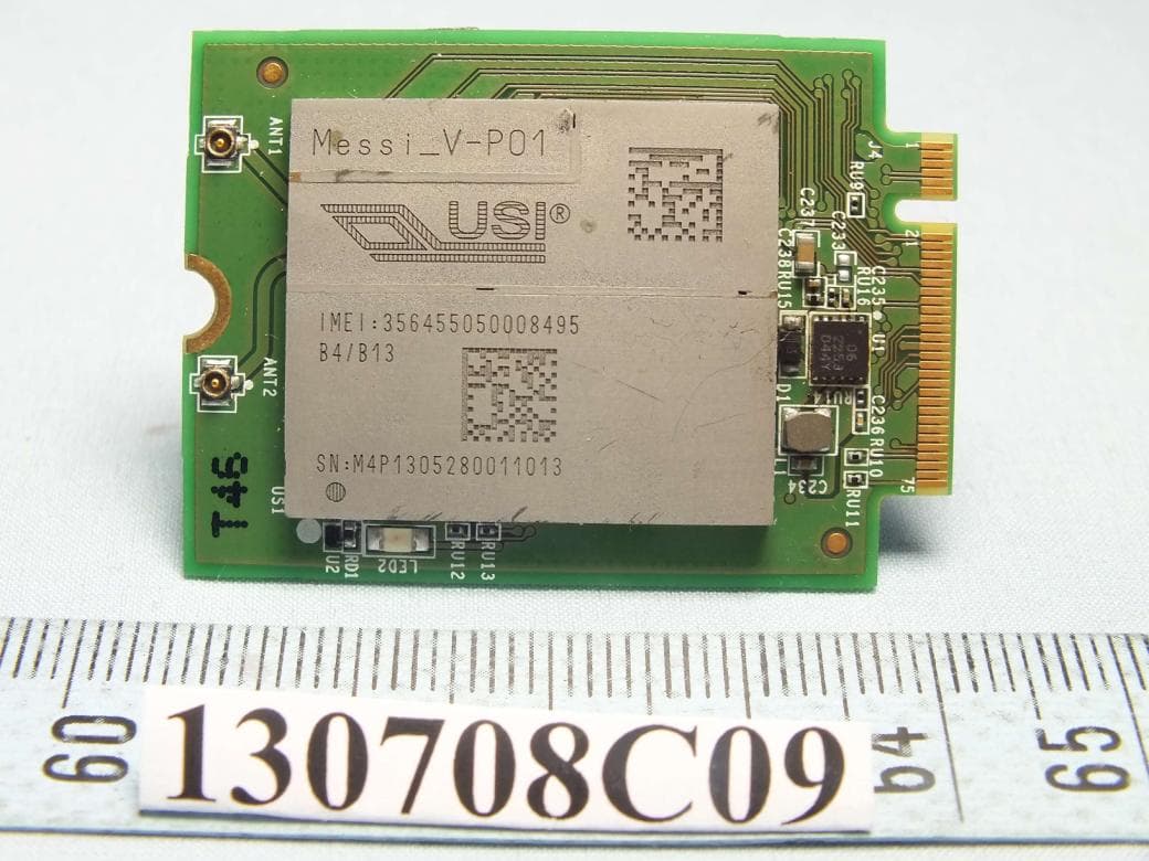
IXMMESSI-V
Sep 29, 2013LTE Module
Equipment Class
JBP - Part 15 Class B Computing Device Peripheral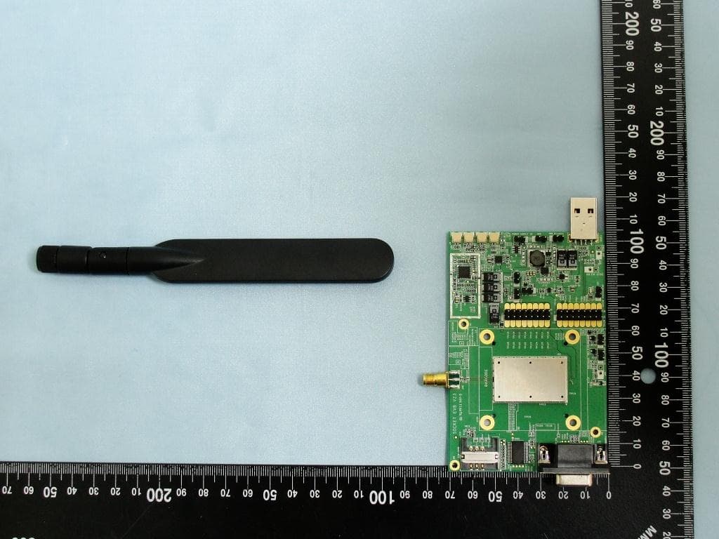
IXM-UNA850
Oct 01, 2012UNA 850 module
Equipment Class
PCB - PCS Licensed Transmitter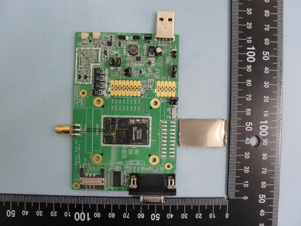
IXM-UNA900
Apr 19, 2012WWAN Module
Equipment Class
PCB - PCS Licensed Transmitter
IXMUGNAS-P3
Jul 28, 2011NETWORK ATTACHED STORAGE
Equipment Class
DTS - Digital Transmission System