IXMCF114100Wireless LAN CF Card
Universal Scientific Industrial Co., Ltd.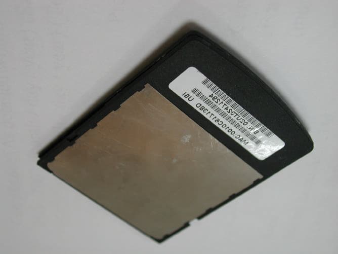
Click to zoom
Application Details
- Equipment Class
- DTS - Digital Transmission System
- Date of Grant
- Sep 23, 2002
- Application Purpose
- Original Equipment
- Date of Application
- Sep 23, 2002
- Equipment Note
- Wireless LAN CF Card
- Frequency Range
- 2412.00000000 - 2462.00000000
- Country
- Taiwan
Documents & Files
Document Text
Text extracted from the exhibit documents filed with the FCC. Open a document above to read the original.
Users Manual
USI 802.11b WLAN CF Card Quick User Guide Special Issue Regarding to the Configurations of the WLAN CF Card This WLAN CF Card, is designed and classified as a HAND-HELD device. It is designed to be adapted with the hand-held device such as PDA, PocketPC, Palm etc. The configuration other than these usage (e.g. with the body-worn manner) is not intended by the manufacturer and is strictly prohibited. In addition, for your own safety, it is recommended that keeping at least 20cm separation between the device and your body to minimize the possible RF exposure. This device must not be co-located or operating in conjunction with any other antenna or transmitter in order to avoid mutual interference. Index 1. Introduction..................................................................................................................... 4 1.1 Network Scenarios................................................................................................ 4 1.2 Features................................................................................................................. 4 2. Installing and Configuring the Wireless Network for Pocket PC................................... 6 2.1 Preparation............................................................................................................ 6 2.2 Installing the Driver and Utility from a CDROM................................................ 6 2.3 Configuring the Wireless Network in Windows CE............................................ 8 3. Using the Client Manager Utility.................................................................................. 15 3.1 Installing the Client Manager............................................................................. 15 3.2 The meaning of Tack Tray Icons........................................................................ 15 3.3 Using the Client Manager................................................................................... 15 4. Card Specifications....................................................................................................... 18 4.1 Physical Specifications....................................................................................... 18 4.2 Power Characteristics......................................................................................... 18 4.3 Networking Characteristics................................................................................. 18 4.4 Radio Characteristics.......................................................................................... 19 Basic Troubleshooting...................................................................................................... 21 Index of Flow Chart Figure 1............................................................................................................... 5 Figure 2............................................................................................................... 7 Figure 3............................................................................................................... 8 Figure 4............................................................................................................... 9 Figure 5............................................................................................................. 11 Figure 6............................................................................................................. 12 Figure 7............................................................................................................. 13 Figure 8............................................................................................................. 14 Figure 9............................................................................................................. 16 Figure 10........................................................................................................... 16 Figure 11........................................................................................................... 17 1. Introduction Wireless LAN is local area networking without wires, which uses radio frequencies to transmit and receive data between PC’s or other network devices without wires or cables. Wireless LAN configurations include independent networks suitable for small or temporary peer-to-peer configurations and infrastructure networks, offering fully distributed data connectivity via micro cells and roaming. The USI 802.11b WLAN CF card allows Pocket/Handheld PC (Windows CE 3.0 or 4.0) devices to connect to a Wi-Fi TM IEEE 802.11b wireless local area network (LAN), or communicate directly with other devices enabled for wireless LAN connectivity. The USI 802.11b WLAN CF card is designed to meet the mobility, performance, security, interoperability, management, and reliability requirements of IEEE 802.11b high data rate standard. 1.1 Network Scenarios 1.2 Features Features includes: • CompactFlash TM form factor fits devices with CF Type I and Type II extended card slots • Functions with Pocket/Handhelp PC (Windows CE 3.0 or 4.0) devices with CF Type I and Type II extended card slots • Compliant with 11 Mbps 802.11b high-speed specification • Data rate 11/5.5/2/1 Mbps automatic fallback under noisy environment • Power Management for decreased power consumption • Interoperable with IEEE 802.11b compliant equipment • Supports full mobility and seamless roaming from cell to cell • User-friendly client manager utility • Supports 64 and 128-bit WEP (Wired equivalent privacy). • Direct Sequence Spread Spectrum (DSSS) technology provides robust, • interference-resistant and secure wireless connection. • Wireless connection without the hassles and cost of cabling. • Greater flexibility to locate or move networked device • The USI 802.11b WLAN CF Card has only one LED indicators o Transmit/Receive (flashing green) o Power ON/OFF LED(flashing red) Figure 1 2. Installing and Configuring the Wireless Network for Pocket PC 2.…
Text truncated - open the document above for the full version.
Block Diagram
Blockdiagram THESEUS Baseband Chipset & HERMES MAC Chipset August 14, 2002 WLAN Compact Flash Card Wireless LAN Card Designed with Ruby RF Chipset, DATA/ADDRESS SWITCH FLASH DATA/ADDRESS SRAM RF_RX RUBY ANTENNA DATA/ADDRESS BASEBAND RF CONVERTER OP AMP ATTENUATOR (Frequency of oscillator : 22MHz) BUFFER POWER DETECT RF POWER AMPLIFIER DATA BASE BAND THESEUS (Oscillator : 22MHz) Q MAC HERMES I POWER DETECT CF CARD CONNECTOR Interface TYPE I RF_TX RF_TX POWER SUPPLY
Cover Letter(s)
Training Research Co., Ltd. 255 Nanyang Street, Shijr, Taipei Hsien 221, Taiwan, R.O.C. TEL: 886-2-26935155 FAX: 886-2-26934440 TRCSince1985 ® Sep 12, 2002 RE: Universal Scientific Industrial Co., Ltd. FCC ID: IXMCF114100 Dear Timothy: After the review of your comments, we have made some modifications upon your advice; they are summarized as follows: 1. The Block Diagram updated with adding all the frequency of the oscillators shown, is uploaded. 2. The manufacturer wants the product being locked in its working configuration at the “HANDHELD” mode. Please refer to the declaration of locking the configuration by the manufacturer attached. 3. Thanks for your kindly reminding about the report. The negative sign is inserted and please find the modified one uploaded. 4. The Compliance Information is inserted to the manual. Please find the modified one uploaded. Should you have any questions or more information is needed, please don’t hesitate to ask us. Thank you. Sincerely yours, Eric Wong Project Engineer Training Research Co Ltd.
Cover Letter(s)
Training Research Co., Ltd. 255 Nanyang Street, Shijr, Taipei Hsien 221, Taiwan, R.O.C. TEL: 886-2-26935155 FAX: 886-2-26934440 Email: [email protected] TRCSince1985 ® September 24, 2002 RE: Universal Scientific Industrial Co., Ltd. FCC ID: IXMCF114100 Dear Timothy: After the review of your comments, we have made some response upon your advice; they are summarized as follows: 1. The testing utilities under the WINCE or Palm OS (hand-held status) have not been developed till now. That’s why we can only tested with the Notebook via the CompactFlash-PCMCIA adapter, in the same way as the other cases granted before. 2. The driver bundled with the product is only for the use of the WINCE OS, also the manual will not have any issue instructing the user to use the card other than hand-held device. That’s why we claim that the device not intended for the use of the statue other than hand-held. Should you have any questions or more information is needed, please don’t hesitate to ask us. Thank you. Sincerely yours, Eric Wong Project Engineer Training Research Co Ltd.
Cover Letter(s)
American Telecommunications Certification Body Inc. 6731 Whittier Ave, McLean, VA 22101 September 6, 2002 RE: Universal Scientific Industrial Co., Ltd. FCC ID: IXMCF114100 After a review of the submitted information, I have a few comments on the above referenced Application. These comments are all made upon the assumption that the EUT's full conducted output power is 21 mW and the antenna gain is 2.5 dBi. 1) The block diagram should show the frequency of all oscillators in the transmitter portion of the device (CFR 2.1033(a)(5)). Please provide a corrected copy. 2) CF cards must be treated similar to PCMCIA Cards unless specific configurations can be “locked in” (controlled use via specific hardware or software issues). a) From the users manual, it appears that the only supported host configuration is Windows CE. Please explain if this is the only operating system to be supported. b) Please explain how hardware and/or software will be used to prevent use in laptops or other devices. c) If the devices intended use is for PDA’s or hand held equipment only, please explain why the EMC report shows the device tested in laptop. Please describe how laptop data applies to hand held device, and/or re-test in hand held if appropriate. d) The phrase “This device and its antenna must not be co-located or operating in conjunction with any other antenna or transmitter” must be added to the MPE statements in the users manual. If the configuration can not adequately be “locked in”, then the following will apply. Please note that in the past 2 weeks, the FCC has recently changed how to treat these types of devices for MPE/SAR related issues. 2.5 cm is no longer considered acceptable spacing for laptop configurations. The FCC has instructed us that we must consider that these device might be used in a touch position to the body. Assuming this device is for general purpose use please explain: a) The device should be classified for portable and/or mobile use. b) State that the antenna may be closer than 20 cm. c) Since the output power (either conducted or EIRP, Conducted = 21 mW, EIRP = 36.6) exceeds 24.6 mW ( a number specified by the FCC), this device will require SAR testing. Please note that testing must be performed in a touch position to the SAR phantom. Alternatively, the power may be lowered such that the EIRP is less than 24.6 mW. e) If SAR testing is performed, the Users Manual should contain information regarding the device and that it has met with SAR requirements. Additionally the current MPE statements would need to be modified. 3) FYI, one of the margins in Table 11 is lacking a negative sign. z Page 2September 6, 2002 4) If this device may be considered as a PC Peripheral, then an compliance information sheet should be included in the manual on the same page as the FCC statements (page 20 of 23 of the users manual). This information should contain the following information regarding DoC compliance: COMPLIANCE INFORMATION (47CFR 2.1077) If a product is tested and authorized under a Declaration of Conformity, a compliance information statement shall be supplied with the product at the time of marketing or importation, containing the following information: (1) Identification of the product, i.e. name and model number. (2) The identification, by name, address and telephone number, of the responsible party. The responsible party is defined as either the manufacturer, or if the equipment is imported, the importer. The responsible party for a Declaration of Conformity must be located within the United States. Timothy R. Johnson Examining Engineer mailto: [email protected] The items indicated above must be submitted before processing can continue on the above referenced application. Failure to provide the requested information may result in application termination. Correspondence should be considered part of the permanent submission and may be viewed from the Internet after a Grant of Equipment Authorization is issued. Please do not respond to this correspondence using the email reply button. In order for your response to be processed expeditiously, you must submit your documents through the AmericanTCB.com website. Also, please note that partial responses increase processing time and should not be submitted. Any questions about the content of this correspondence should be directed to the sender.
Cover Letter(s)
American Telecommunications Certification Body Inc. 6731 Whittier Ave, McLean, VA 22101 September 18, 2002 RE: Universal Scientific Industrial Co., Ltd. FCC ID: IXMCF114100 After a review of the submitted information, I have a few comments on the above referenced Application. These comments are all made upon the assumption that the EUT's full conducted output power is 21 mW and the antenna gain is 2.5 dBi. 1) Your response stated hand held use only. EMC report shows test in laptop. Please describe how laptop data applies to hand held device, and/or re-test in hand held if appropriate. 2) Users manual now state hand held use only. Please explain how hardware and/or software will be used to prevent use in laptops or other devices (i.e. Drivers will only be given and supported for the Windows CE operating system. Note: Instructing the users to how to use a device away from the body is not enough to classify the device as mobile. The device should have software or hardware limitations or be designed for such use to ensure that this device meets RF exposure requirements. FYI, Reference to "locked in" configurations are considered controlled configurations. An example of this is this device is sold only when integrated into a particular product and is not sold by itself for general users. Timothy R. Johnson Examining Engineer mailto: [email protected] The items indicated above must be submitted before processing can continue on the above referenced application. Failure to provide the requested information may result in application termination. Correspondence should be considered part of the permanent submission and may be viewed from the Internet after a Grant of Equipment Authorization is issued. Please do not respond to this correspondence using the email reply button. In order for your response to be processed expeditiously, you must submit your documents through the AmericanTCB.com website. Also, please note that partial responses increase processing time and should not be submitted. Any questions about the content of this correspondence should be directed to the sender.
External Photos
External Photo of USI 802.11b CompactFlash Card External Photo of USI 802.11b CompactFlash Card
ID Label/Location Info
Label Location of USI 802.11b CompactFlash Card
Internal Photos
Internal Photo of USI 802.11b CompactFlash Card Internal Photo of USI 802.11b CompactFlash Card Internal Photo of USI 802.11b CompactFlash Card Internal Photo of USI 802.11b CompactFlash Card Internal Photo of USI 802.11b CompactFlash Card
RF Exposure Info
Training Research Co., Ltd. No. 2, Lane 194, Huan-Ho St., Hsi-Chih, Taipei Hsien 221, Taiwan, R.O.C. TEL: 886-2-26935155 FAX: 886-2-26934440 TRCSince1985 ® Measurement of MPE 1. Foreword In adopt with the Human Exposure IEEE C95.1, and according to the FCC 1.1310. The Maximum Permissible Exposure (MPE) is obligated to measure in order to prove the safety of radiation harmfulness to the human body. The Gain of the antenna used is measured in an Anechoic chamber. The maximum total power to the antenna is to be recorded. By adopting the Friis Transmission Formula and the power gain of the antenna, we can find the distance right away from the product, where the limit of the MPE is. 2. Description of EUT EUT : USI 802.11B CompactFlash Card Classification : Mobile Device (i) Under normal use condition, the antenna is at least 20cm away from the user; (ii) Warning statement for keeping 20cm separation distance and the prohibition of operating next to the person has been printed in the user’s manual Model No. : CF114100 Granted FCC ID : IXMCF114100 Frequency Range : 2.412 GHz ~ 2.462GHz Antenna Kit : 1 chip antenna Supported Channel: 11 Channel Modulation Skill : DBPSK, DQPSK, CCK Power Type : Powered by the CompactFlash slot of the client’s device Applicant : Universal Scientific Industrial Co., Ltd. 135, Lane 351, Taiping Rd., Sect.1, Tsao Tuen, Nan-Tou 542, Taiwan, R.O.C. Training Research Co., Ltd. No. 2, Lane 194, Huan-Ho St., Hsi-Chih, Taipei Hsien 221, Taiwan, R.O.C. TEL: 886-2-26935155 FAX: 886-2-26934440 TRCSince1985 ® 3. Limits for Maximum Permissible Exposure (MPE) Frequency Range (MHz) Electric Field Strength (V/m) Magnetic Filed Strength (H) (A/m) Power Density (S) (mW/cm2) Averaging Time |E| 2 , |H| 2 or S (minutes) (A) Limits for Occupational/Controlled Exposure 0.3-3.0 614 1.63 100 6 3.0-30 1842/f 4.89/f 900/f 2 6 30-300 61.4 0.163 1.0 6 300-1500 -- -- f/300 6 1500-100,000 -- -- 5 6 (B) Limits for General Population/Uncontrolled Exposure 0.3-1.34 614 1.63 100 30 1.34-30 824/f 2.19/f 180/f 2 30 30-300 27.5 0.073 0.2 30 300-1500 -- -- f/1500 30 1500-100,000 -- -- 1.0 30 [The EUT is tested in transmit and receive modes and in the first, middle and the last channel separately. The following shows only our observation have the greatest emissions.] According to OET BULLETIN 56 Fourth Edition/August 1999, Equation for Predicting RF Fields: Friis Transmission Formula: 23 22 /1029.7 )20(4 778.161.20 4 cmmW R PG S − ×= × == ππ Where: S = power density (in appropriate units, e.g. mW/cm 2 ) P = power input to the antenna (in appropriate units, e.g., mW) G = power gain of the antenna in the direction of interest relative to an isotropic radiator R = distance to the center of radiation of the antenna (appropriate units, e.g., cm) The Numeric gain G of antenna with a gain specified in dB is determined by: G = Log -1 (dB antenna gain/10) G = Log -1 (2.5 / 10) = 1.778 HF R&D Print date 02/08/14 Long Shape TYPE 230 Aug. 7, 02 Multilayer Ceramic Antenna for Bluetooth (ISM Band 2.40GHz) 4311 115 00230 AN2300000708031K Grant Lin/Cliff2002-08- 07 Page 1 sheet 190-1 A4 spec.doc Phycomp Taiwan Ltd. MULTILAYER CERAMIC ANTENNA (TYPE 230) FOR BLUETOOTH & WLAN IEEE 802.11b (2.45G Hz ISM Band) (Long Shape) QUICK REFERENCE DATA Dimension7.8* 3.6 * 0.9 mm Central Frequency*2.37 GHz Bandwidth >100 MHz Gain 2.5dBi max VSWR 2.0 max Polarization Linear Azimuth Omni-directional Impedance 50Ù Operating Temperature-55~125 o C TerminationNi/Sn (Environmentally-Friendly Leadless) Resistance to soldering heat260 o C, 10 sec. Maximum Power1W * Based on customer PCB Special Environmental Concerns- Green Products Design: The foil making process is using environmentally-friendly aqueous solvent technology. Termination is lead free (Pb free) and packing materials can be re-cycled HF R&D Print date 02/08/14 Long Shape TYPE 230 Aug. 7, 02 Multilayer Ceramic Antenna for Bluetooth (ISM Band 2.40GHz) 4311 115 00230 AN2300000708031K Grant Lin/Cliff2002-08- 07 Page 1 sheet 190-1 A4 spec.doc Phycomp Taiwan Ltd. APPLICATION DIMENSIONAL DATA Figure DimensionPort L : 7.8 +/-0.25 mm W: 3.6 +/- 0.2 mm T: 0.9 +/- 0.2 mm F: 1.25 +/- 0.25 mm C: 0.4 +/-0.2 mm S1: 1.25 +/- 0.25 mm S2: 1.40 +/- 0.25 mm - - - Feed Termination - NC Solder Termination Only Optional NC Solder Termination Only HF R&D Print date 02/08/14 Long Shape TYPE 230 Aug. 7, 02 Multilayer Ceramic Antenna for Bluetooth (ISM Band 2.40GHz) 4311 115 00230 AN2300000708031K Grant Lin/Cliff2002-08- 07 Page 3 sheet 190-3 A4 spec.doc Phycomp Taiwan Ltd. SOLDER LAND PATTERN Figure Dimensions Remark L W F C S1 S2 9 ± 0.10 mm 4.4 ± 0.20 mm 1.40 ± 0.25 mm 0.80 ± 0.20 mm 1.40 ± 0.25 mm 1.60 ± 0.25 mm Feed Pad NC Mount Pad Only Optional NC Mount Pad Only Typical Radiation Pattern Polar Plot -90 -45 0 45 90 135 180 225 H-Plane -90 -45 0 45 90 135 180 225 E-Plane HF R&D Print date 02/08/14 Long Shape TYPE 230 Aug. 7, 02 Multilayer Ceramic Antenna for Bluetooth (ISM Band 2.40GHz) 4311 115 00230 AN2300000708031K Grant Lin/Cliff2002-08- 07 Page 4 sheet 190-4 A4 spec.doc Phycomp Taiwan Ltd. Typical Return Loss and SWR RELIABILITY DATA (Reference to IEC Specification) IEC 384-10/ CECC 32 100 CLAUSE IEC 60068-2 TEST METHOD TESTPROCEDUREREQUIREMENTS 4.4MountingThe antenna can be mounted on printed- circuit boards or ceramic substrates by applying wave soldering, reflow soldering (including vapour phase soldering) or conductive adhesive No visible damage 4.5Visual inspection and dimension check Any applicable method using × 10 magnification In accordance with specification (chip off 4mm) 4.6.1AntennaCentral Frequency 2.37GHz at 20 o C Per customer request board HF R&D Print date 02/08/14 Long Shape TYPE 230 Aug. 7, 02 Multilayer Ceramic Antenna for Bluetooth (ISM Band 2.40GHz) 4311 115 00230 AN2300000708031K Grant Lin/Cliff2002-08- 07 Page 5 sheet 190-5 A4 spec.doc Phycomp Taiwan Ltd. IEC 384-10/ CECC 32 100 CLAUSE IEC 60068-2 TEST METHOD TESTPROCEDUREREQUIREMENTS 4.8AdhesionA force of 3 N applied fo…
Text truncated - open the document above for the full version.
Test Report
Test Report -------------------------------------------------------------------------------- 1/44 Report No.: U1315674 Training Research Co., Ltd., TEL: 886-2-26935155, Fax: 886-2-26934440 MEASUREMENT REPORT of WIRELESS LAN COMPACTFLASH CARD Applicant : Universal Scientific Industrial Co., Ltd. Model No. : CF114100 EUT : USI 802.11b CompactFlash Card FCC ID : IXMCF114100 Report No. : U1315674 Tested by : Training Research Co., Ltd. TEL : 886-2-26935155 FAX : 886-2-26934440 255, Nanyang Street, Shijr, Taipei Hsien 221, Taiwan, R.O.C. Test Report -------------------------------------------------------------------------------- 3/44 Report No.: U1315674 Training Research Co., Ltd., TEL: 886-2-26935155, Fax: 886-2-26934440 Tables of Contents I. GENERAL ......................................................................................................................... 4 1.1 Introduction .................................................................................................................. 5 1.2 Description of EUT ....................................................................................................... 5 1.3 Description of Support Equipment ................................................................................. 6 1.4 Configuration of System Under Test .............................................................................. 8 1.5 Verify the Frequency and Channel ................................................................................. 9 1.6 Test Procedure ............................................................................................................ 10 1.7 Location of the Test Site ............................................................................................... 10 1.8 General Test Condition ................................................................................................. 10 II. Section 15.101(a) : Equipment Authorization of Unintentional Radiators....................... 11 III. Section 15.203 : Antenna Requirement............................................................................. 12 IV. Section 15.207 : Power Line Conducted Emissions for AC Powered Units ................... 13 4.1 Test Condition & Setup ................................................................................................ 13 4.2 List of Test Instruments ................................................................................................ 13 4.3 Test Configuration ........................................................................................................ 14 4.4 Test Result of Conducted Emissions ............................................................................. 15 V. Section 15.247(a) : Technical Description of the EUT..................................................... 18 VI. Section 15.247(a)(2) : Bandwidth for Direct Sequence System ..................................... 19 6.1 Test Condition & Setup ................................................................................................ 19 6.2 Test Instruments Configuration ...................................................................................... 19 6.3 List of Test Instruments ................................................................................................ 19 6.4 Test Result of Bandwidth ............................................................................................... 20 VII. Section 15.247(b) : Power Output .................................................................................... 24 7.1 Test Condition & Setup ................................................................................................ 24 7.2 List of Test Instruments ................................................................................................ 24 7.3 Test Result ................................................................................................................... 25 VIII.Section 15.247(c) : Spurious Emissions (Radiated) ....................................................... 26 8.1 Test Condition & Setup ................................................................................................ 26 8.2 List of Test Instruments ................................................................................................ 27 8.3 Test Instruments Configuration ...................................................................................... 28 8.4 Test Result of Spurious Radiated Emissions .................................................................. 29 8.5 Test Result of Band-edge Compliance............................................................................ 36 IX.Section 15.247(d) : Power Spectral Density ...................................................................... 39 9.1 Test Condition & Setup ................................................................................................ 39 9.2 Test Instruments Configuration ...................................................................................... 39 9.3 List of Test Instruments.................................................................................................. 39 Test Report -------------------------------------------------------------------------------- 4/44 Report No.: U1315674 Training Research Co., Ltd., TEL: 886-2-26935155, Fax: 886-2-26934440 9.4 Test Result of Power Spectral Density .......................................................................... 40 Appendix A: Set Up Procedure ............................................................................................... 44 Test Report -------------------------------------------------------------------------------- 5/44 Report No.: U1315674 Training Research Co., Ltd., TEL: 886-2-26935155, Fax: 886-2-26934440 . GENERAL 1.1 Introduction The following measurement report is submitted on behalf of Applicant in support of a wireless access CompactFlash card certification in accordance wit…
Text truncated - open the document above for the full version.
Test Report
Test Report ------------------------------------------------------------------------------ 24/44 Report No.: U1315674 (Version II) Training Research Co., Ltd., TEL: 886-2-26935155, Fax: 886-2-26934440 VII. Section 15.247(b): Power Output 7.1 Test Condition & Setup 1. The output of the transmitter is connected to the BOONTON RF Power Meter. 2. The calibration is performed before every tests. The values of the output power of the EUT will shown in the dBm directly are the transmitter output peak power. Recording as follows. 7.2 List of Test Instruments Instrument Name Model No. Brand Serial No. Last Cali. Due On RF Power Meter 4532 BOONTON 117501 02/03/21 03/03/21 EUT BOONTON 4532 RF Power Meter Test Report ------------------------------------------------------------------------------ 25/44 Report No.: U1315674 (Version II) Training Research Co., Ltd., TEL: 886-2-26935155, Fax: 886-2-26934440 7.3 Test Result Formula: Signal generator + |Cable loss| = Output peak power Signal Generator Cable Loss Limit Output peak power Channel dBm dBm (DTS) dBm mW CH1 11.31 0.00 100mW 11.31 13.60 CH6 10.97 0.00 100mW 10.97 12.50 CH11 10.74 0.00 100mW 10.74 11.86 Note: The limit is varying according to the equipment class, listed below: 1. Digital Transmission System (DTS): 100mW 2. Spread Spectrum Transmitter (DSS): 1W
Contact Information
Applicant
Martin Shih(Section Manager)
Technical Contact
Training Research Co., Ltd.Eric Wong
[email protected]+886-2-26935155
255 Nanyang Street, Shijr, · Taipei Hsien · Taiwan
Non-Technical Contact
Training Research Co, Ltd.Eric Wong
[email protected]+886-2-26935155
Test Firm
Training Research Co., Ltd.Jack Tsai
Technical Specifications
| # | Rule Parts | Frequency Range | Power Output |
|---|---|---|---|
| 1 | 15C | 2.41 GHz - 2.46 GHz | 13.60 mW |
Other Applications from Universal Scientific Industrial Co., Ltd.
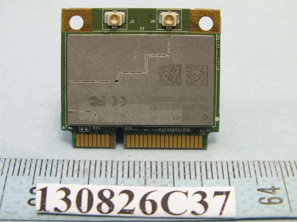
IXM-UNA-P3
Nov 21, 20133G Module
Equipment Class
PCB - PCS Licensed Transmitter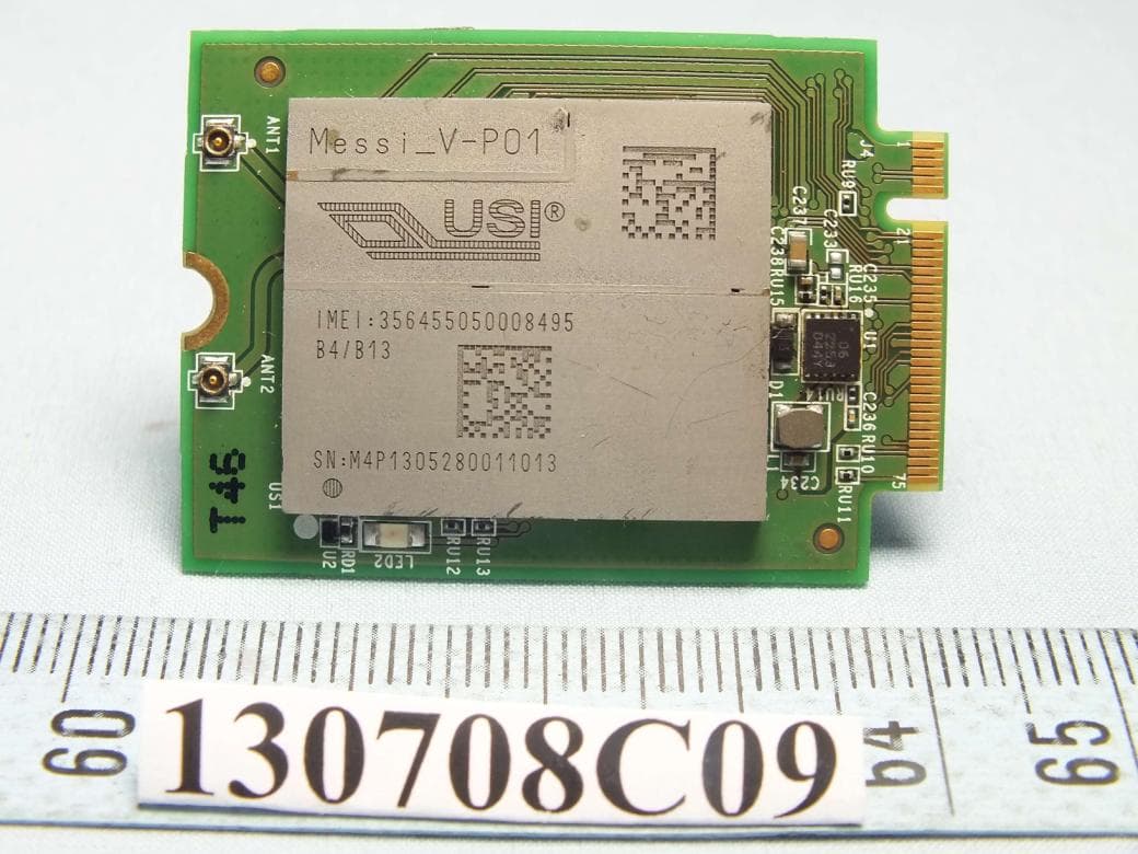
IXMMESSI-V
Sep 29, 2013LTE Module
Equipment Class
JBP - Part 15 Class B Computing Device Peripheral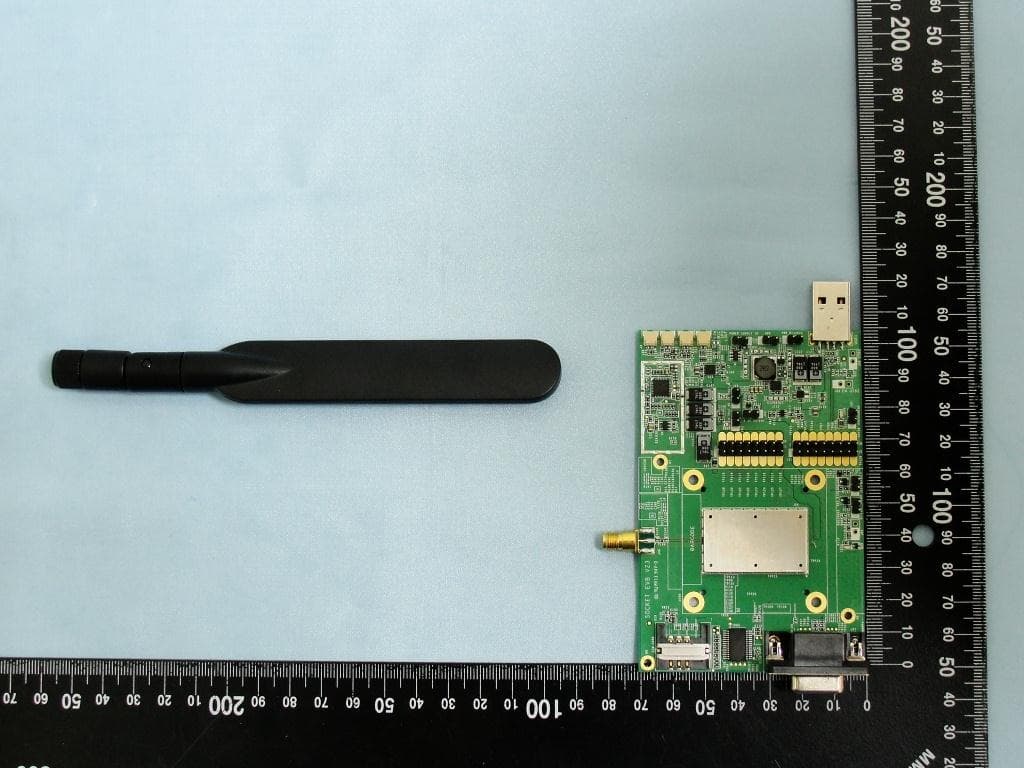
IXM-UNA850
Oct 01, 2012UNA 850 module
Equipment Class
PCB - PCS Licensed Transmitter
IXM-UNA900
Apr 19, 2012WWAN Module
Equipment Class
PCB - PCS Licensed Transmitter
IXMUGNAS-P3
Jul 28, 2011NETWORK ATTACHED STORAGE
Equipment Class
DTS - Digital Transmission System