IXMUB22111SBluetooth Module
Universal Scientific Industrial Co., Ltd.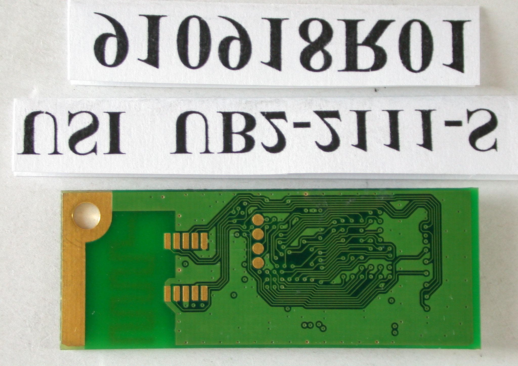
Click to zoom
Application Details
- Equipment Class
- DSS - Part 15 Spread Spectrum Transmitter
- Date of Grant
- Nov 04, 2002
- Application Purpose
- Original Equipment
- Date of Application
- Nov 04, 2002
- Equipment Note
- Bluetooth Module
- Frequency Range
- 2402.00000000 - 2480.00000000
- Country
- Taiwan
Documents & Files
Document Text
Text extracted from the exhibit documents filed with the FCC. Open a document above to read the original.
Users Manual
Page 1 135, Lane 351, Taiping Road, Sec . 1, Nan-Tou , Taiwan; (049)2325876; www.usi.com.tw Rev2.0 Oct/29/2002 UB2-2111-S User’s Manual With the Bluetooth Software BTW 1.2.x or above Trademark Information BTW is a product of Widcomm Inc. Windows, Windows 98, Windows NT, Windows Millennium, Windows XP are trademarks of Microsoft Corporation. Internet Explorer is a product of Microsoft Corporation. The BLUETOOTH trademarks are owned by Bluetooth SIG and used by USI under license. T39 handset is a product of Ericsson. All other trade names mentioned in this document or the other documentation provided with this product are trademarkes or registered trademarks of their respective holders. Page 2 135, Lane 351, Taiping Road, Sec . 1, Nan-Tou , Taiwan; (049)2325876; www.usi.com.tw Rev2.0 Oct/29/2002 UB2-2111-S User’s Manual With the Bluetooth Software BTW 1.2.x or above Table of Contents ItemPage Hardware Specification3 Connector Pin outs4 Mounting Guide for Antenna Radiation5 Impedance Matching of Antenna6 System Requirement7 Bluetooth Software Install step by Step8-14 Start Connection Over The Bluetooth Airwaves – File Transfer15 - 18 Connecting Over The Bluetooth Airwaves – Security19 - 20 Start Connection Over The Bluetooth Airwaves – Dial Up Networking Profile21 -23 Technical Support24 Page 3 135, Lane 351, Taiping Road, Sec . 1, Nan-Tou , Taiwan; (049)2325876; www.usi.com.tw Rev2.0 Oct/29/2002 UB2-2111-S User’s Manual With the Bluetooth Software BTW 1.2.x or above Hardware Specification l Conducted Power: 0.8mW l Frequency Range: 2.402GHz~2.4835GHz l Modulation: GFSK l Sensitivity: -80 dbm l Data Rate: Asynchronous:723.2kbps/57.6kbps Synchronous:433.9kbps/433.9kbps l Operating Voltage: +3.3VD l Operating systems: Windows 98SE Windows ME Windows 2000 Windows XP l AntennaPeak Gain @ 2.45GHz: 0.5dBi l Dimesion Length: 36.00 mm Width: 13.80 mm Height: 3.8 mm Page 4 135, Lane 351, Taiping Road, Sec . 1, Nan-Tou , Taiwan; (049)2325876; www.usi.com.tw Rev2.0 Oct/29/2002 UB2-2111-S User’s Manual With the Bluetooth Software BTW 1.2.x or above Connector pinouts Type-A PIN # Type-B PIN # Module Pin Name Usage for Platforms Description 12 GNDGND Ground. 24 USB_D+USB_D+ USB Data +. Must be routed with USB_D- as a 90Ω differential pair. 36 USB_D-USB_D- USB Data –. Must be routed with USB_D+ as a 90Ω differential pair. 48 USB_PWRUSB_PWR This is a 5V rail that is used by bus-powered USB devices. The module does not actually draw power from this pin, uses this pin to detect whether the USB host port is powered so as to avoid latch-up conditions. 510 RSVDTest Point, COEX1 Reserved. This pin may be used for resolving coexistence with the 802.11 radio(s) on the MPCI card in the platform. 61 HW_RADIO_DIS#HW_RADIO_DIS# Active low input from the platform to the card to disable all the radios on the module from transmitting. 77 RSVDTest Point, COEX2 Reserved. This pin may be used for resolving coexistence with the 802.11 radio(s) on the MPCI card in the platform. . 85 +3.3V+3V_SUS This is the rail from which the module powers itself (as a self-powered USB device). 93 LED_BT_RadioStateBT_RADIO_ON Active-high LED drive signal for indicating the state of the Bluetooth Radio. This LED should not have a flashing feature. 109 GNDNC Page 5 135, Lane 351, Taiping Road, Sec . 1, Nan-Tou , Taiwan; (049)2325876; www.usi.com.tw Rev2.0 Oct/29/2002 UB2-2111-S User’s Manual With the Bluetooth Software BTW 1.2.x or above Mounting Guide for Antenna Radiation In order to achieve longest communication range, please keep the area surrounding antenna free of grounding or metal housing. UB2-2111-S Antenna Ground should not come in this area Ground Do not completely cover the antenna portion with ground plates. Ground Covering only one side of the antenna is acceptable. But the distance between ground plate and antenna should be keep as far as possible. Ground Page 6 135, Lane 351, Taiping Road, Sec . 1, Nan-Tou , Taiwan; (049)2325876; www.usi.com.tw Rev2.0 Oct/29/2002 UB2-2111-S User’s Manual With the Bluetooth Software BTW 1.2.x or above Impedance Matching of Antenna UB2-2111-S utilizes a monopole printed antenna for radiate communication. Application environments, such as notebooks, PDAs, printers or other handheld devices, both have plastic housings, different motherboards and other mechanism structures. These factors will cause the deviation of antenna central frequency. Therefore, impedance matching of antenna should be optimized for various applications to achieve longest communication range. Please consult USI for further information. Page 7 135, Lane 351, Taiping Road, Sec . 1, Nan-Tou , Taiwan; (049)2325876; www.usi.com.tw Rev2.0 Oct/29/2002 UB2-2111-S User’s Manual With the Bluetooth Software BTW 1.2.x or above System Requirements BTW runs under: - Windows 98 (Second edition) - Millennium (Windows 98 ME) - Windows 2000 - Windows XP During the installation, you need a CD-ROM driver for access to the bundle software. Page 8 135, Lane 351, Taiping Road, Sec . 1, Nan-Tou , Taiwan; (049)2325876; www.usi.com.tw Rev2.0 Oct/29/2002 UB2-2111-S User’s Manual With the Bluetooth Software BTW 1.2.x or above Bluetooth Software Install step by step Step 1 Insert the Widcomm BTW CD into the PC’s CDROM drive. Installation proceeds automatically. Since Windows NT does not support USB, the installation of the CD should be done on systems with Windows ’98 or Windows 2000. Step 2 An InstallShield box appears to inform you the installation Wizard is being set up. Please wait. Figure 2. Welcome Window Note: These images were captured from a Windows 2000 system. Your images may look slightly different. Step 3 A Welcome To The Installation Wizard window appears as shown in Figure 2. Select Next to continue the installation process. Page 9 135, Lane 351, Taiping Road, Sec . 1, Nan-Tou , Taiwan; (049)2325876; www.usi.com.tw Rev2.0 Oct/29/2002 UB2-2111-S User’s Manual With the Bluetooth Software BTW 1.2.x or above Figure 3. License Agreement Window S…
Text truncated - open the document above for the full version.
Cover Letter(s)
FCC ID: IXMUB22111S ADT No.910918R01 Modular Approval Request Letter Advance Data Technology Oct. 14, 2002 Dear Application Examiner, Unicersal Scientific Industrial Co., Ltd’s Bluetooth USB module, FCC ID: IXMUB22111S, would like to have your authorization for Module Approval specific to the mobile device such as Notebook. The requirements of Public Notice DA00-1407 have been met and shown on the following statements. 1. “The modular transmitter must have its own RF shielding.”: The radio portion of this module has been shielded, please see exhibition External Photo. 2. “The modular transmitter must have buffered modulation/data inputs.” The EUT has buffered data inputs, it is integrated in chip AM29LV800B. 3. “The modular transmitter must have its own power supply regulation.” There is a regulator in the DC input port, the part number is RICHTEK XC6204B182MR. 4. “The modular transmitter must comply with the antenna requirements of section 15.203 and 15.204(C).” The EUT meets the FCC antenna requirements. The spurious emission, unique antenna connector and photo of antennas are shown in the test report. 5. “The modular transmitter must be tested in a stand-alone configuration” The EUT was tested in a stand-alone configuration via a USB cable. Please see section Photographs of Test Configuration in the test report. 6. “The modular transmitter must be labeled with its own FCC ID number.” Please see exhibition Label Sample for the FCC ID of this module. And also in the exhibition Users Manual, there are instructions give to the OEM on how to label the end product. FCC ID: IXMUB22111S ADT No.910918R01 7. “The modular transmitter must comply with any specific rule or operating requirements applicable to the transmitter and the manufacturer must provide adequate instructions along with the module to explain any such requirements.” The EUT is compliant with all applicable FCC rules. Detail instructions for maintaining compliance are given in the Users Manual. 8. “The modular transmitter must comply with any applicable RF exposure requirements.” The EUT is compliant with all applicable RF exposure requirements. RF Exposure is addressed in the RF exposure exhibition. Please contact me if you have any further questions. Thanks for your attention. Best Regards,
Cover Letter(s)
American Telecommunications Certification Body Inc. 6731 Whittier Ave, McLean, VA 22101 October 21, 2002 RE: FCC ID: IXMUB22111S Attention: Alan Lane I have a few comments on this Application. 1 You have requested modular approval for this device. However, the manual is for a Bluetooth Dongle (step 12 page 8), not a module. Then on page 19 you call it a module. A module would be sold to an OEM for incorporation into a final product, your reference to a Bluetooth Dongle is for a final product already not a module. Please make the documentation consistent. If this is the manual that will be provided with this device, then the device would need to be certified as a Bluetooth Dongle and reference to module will have to be removed. If this is to be a module, please provide the instructions and installation manual that is to be provided to the integrator (OEM) manufacturer and not a manual of a final product. 2 Please change your caution statement on page 18 to reflect the fact that unauthorized modifications may void the users authority to operate the device, not just that it may violate FCC regulations. You could for example add the words – “and may void the user;s right to operate the equipment” at the end of the existing statement. 3 Pages 19, 20 and 21 have conflicting rf exposure statements. On page 19 you state that 20cm must be maintained, yet on page 20 and 21 you state 2.5cm must be maintained. Please make the manual consistent in the area of rf compliance. xx Dennis Ward mailto:[email protected] The items indicated above must be submitted before processing can continue on the above referenced application. Failure to provide the requested information may result in application termination. Correspondence should be considered part of the permanent submission and may be viewed from the Internet after a Grant of Equipment Authorization is issued. Please do not respond to this correspondence using the email reply button. In order for your response to be processed expeditiously, you must submit your documents through the AmericanTCB.com website. Also, please note that partial responses increase processing time and should not be submitted. Any questions about the content of this correspondence should be directed to the sender.
External Photos
Page 1 ANNEX PHOTOGRAPHS OF EUT Page 3
ID Label/Location Info
USI UB2-2111-S Adhesive Area USI UB2-2111-S FOR HOME OR FCC Tested to Comply With FCC Standards FCCID:IXMUB22111S 電波: XXXXXXXX 10.17.2002 25.00 19.40 R XXXXXXX XXXXXXX Rating:3.3V 0560 FOR HOME OR OFFICE USE Tested to Comply With FCC Standards IC: xxxxxxxxxx 0.1MAX. Adhesive Paper Label (On The Shielding) 1:1 Wink 02 R SYM DESCRIPTION DATE DWNDATE TOLERANCE UNLESS OTHERWISE SPECIFIED SCALE DRAWING NO. SHEET REV TITLE Universal Scientific Industrial Co., Ltd. USI APPDATE UNIT ±0.1 mm NOTES: 1) MATERIAL: 3M9448 2.4DS4 PDF 檔案以 "PDF 製作工廠" 試用版建立 http://www.fineprint.com
Internal Photos
Page 2 Page 4
Operational Description
FCC ID: IXMUB22111S ADT No.910918R01 Operational Description The transmitter of the EUT is seeking for Module Approval specific to the host equipment such as Notebook. The antenna type is printed antenna and no antenna connector. Under normal use condition, the user has to keep at least 2.5cm separation distance between radiator and the body of the user. The other instruction, please have a look at the users manual. This device is a Frequency Hopping device with 79 hopping frequencies.
RF Exposure Info
FCC ID: IXMUB22111S ADT No.: 910918R01 FCC TEST REPORT REPORT NO.: RF910918R02 MODEL NO.:UB2-2111-S ACCORDING: FCC Guidelines for Human Exposure IEEE C95.1 APPLICANT:Universal Scientific Industrial Co., Ltd. ADDRESS:141, Lane 351, Taiping Road, Sec. 1, Tsao Tuen, Nan-Tou, Taiwan, R.O.C. ISSUED BY:Advance Data Technology Corporation LAB LOCATION:47 14th Lin, Chiapau Tsun, Linko, Taipei, Taiwan, R.O.C. 0528 ILAC MRA Lab Code: 200102-0 FCC ID: IXMUB22111S ADT No.: 910918R01 RF Exposure Measurement (Portable Device) 1. Introduction 2.4GHz frequency band is regarded specially as a dangerous band for its heating harmfulness to the human body. That’s why microwave oven is operating in this frequency band. The manufacturer whose product is working in this frequency band is obligatory to prove the harmfulness of his product. In this document, we try to prove the safety of radiation harmfulness to the human body for our product. The limit for Maximum Permissible Exposure (MPE) specified in FCC 1.1310 is followed. The Gain of the antenna used in this product is measured in a Fully Anechoic Chamber (FAC), and the maximum total power input to the antenna is measured. Through the Friis transmission formula and the maximum gain of the antenna, we can calculate the distance, away from the product, where the limit of MPE is reached. 2. RF Exposure Limit According to FCC 1.1310: The criteria listed in the following table shall be used to evaluate the environmental impact of human exposure to radio-frequency (RF) radiation as specified in 1.1307(b). FCC ID: IXMUB22111S ADT No.: 910918R01 LIMITS FOR MAXIMUM PERMISSIBLE EXPOSURE (MPE) Frequency Range (MHz) Electric Field Strength (V/m) Magnetic Field Strength (A/m) Power Density (mW/cm 2 ) Average Time (minutes) (A)Limits For Occupational / Control Exposures 30-30061.40.1631.06 300-1500......F/3006 1500-100,000......56 (B)Limits For General Population / Uncontrolled Exposure 30-30027.50.0730.230 300-1500......F/150030 1500-100,000......1.030 F = Frequency in MHz 3. Friis Formula Friis transmission formula : Pd = (Pout*G) / (4*pi*r 2 ) where Pd = power density in mW/cm 2 Pout = output power to antenna in mW G = gain of antenna in linear scale Pi = 3.1416 R = distance between observation point and center of the radiator in cm Pd is the limit of MPE, 1 mW/cm 2 . If we know the maximum Gain of the antenna and the total power input to the antenna, through the calculation, we will know the distance r where the MPE limit is reached. Ref. : David K. Cheng, Field and Wave Electromagnetics, Second Edition, Page 640, Eq. (11-133). 4. EUT Operating condition The software provided by Manufacturer enabled the EUT to transmit and receive data at lowest, middle and highest channel individually. FCC ID: IXMUB22111S ADT No.: 910918R01 5. Test Results 5.1 Antenna Gain The maximum Gain measured in Fully Anechoic Chamber is 0Bi or 1(numeric). 5.2 Output Power Into Antenna & RF Exposure Distance : CHANNEL CHANNEL FREQUENCY (MHz) OUTPUT POWER TO ANTENNA (mW) MINIMUM ALLOWABLE DISTANCE ( r ) FROM SKIN (Centi-Meter) 024020.780.25 3924410.780.25 7824800.810.25 The minimum allowable distance is very close to the enclosure of the antenna. So, the user has no need to worry about the harmfulness of radiation. But it is recommended to always keep, at least, 2.5cm separation distance with the antenna.
Test Report
FCC ID: IXMUB22111S Report No.: RF910918R011Issued: Sept. 30, 2002 FCC TEST REPORT REPORT NO.: RF910918R01 MODEL NO.: UB2-2111-S RECEIVED: Sept. 18, 2002 TESTED: Sept. 19 ~ Sept. 25, 2002 APPLICANT:Universal Scientific Industrial Co., Ltd. ADDRESS:141, Lane 351, Taiping Road, Sec. 1, Tsao Tuen, Nan-Tou, Taiwan, R.O.C. ISSUED BY:Advance Data Technology Corporation LAB LOCATION:47 14th Lin, Chiapau Tsun, Linko, Taipei, Taiwan, R.O.C. This test report consists of 60 pages in total. It may be duplicated completely for legal use with the approval of the applicant. It should not be reproduced except in full, without the written approval of our laboratory. The client should not use it to claim product endorsement by CNLA, NVLAP or any government agencies. The test results in the report only apply to the tested sample. 0528 ILAC MRA Lab Code: 200102-0 FCC ID: IXMUB22111S Report No.: RF910918R012Issued: Sept. 30, 2002 TABLE OF CONTENTS 1CERTIFICATION........................................................................................................4 2SUMMARY OF TEST RESULTS................................................................................5 3GENERAL INFORMATION.........................................................................................6 3.1GENERAL DESCRIPTION OF EUT...........................................................................6 3.2DESCRIPTION OF TEST MODES.............................................................................7 3.3GENERAL DESCRIPTION OF APPLIED STANDARDS.............................................7 3.4DESCRIPTION OF SUPPORT UNITS........................................................................8 4TEST PROCEDURES AND RESULTS.......................................................................9 4.1CONDUCTED EMISSION MEASUREMENT..............................................................9 4.1.1LIMITS OF CONDUCTED EMISSION MEASUREMENT...........................................................9 4.1.2TEST INSTRUMENTS................................................................................................................9 4.1.3TEST PROCEDURES...............................................................................................................10 4.1.4DEVIATION FROM TEST STANDARD.....................................................................................10 4.1.5TEST SETUP............................................................................................................................11 4.1.6EUT OPERATING CONDITIONS.............................................................................................11 4.1.7TEST RESULTS........................................................................................................................12 4.2NUMBER OF HOPPING FREQUENCY USED.........................................................18 4.2.1LIMIT OF HOPPING FREQUENCY USED...............................................................................18 4.2.2TEST INSTRUMENTS..............................................................................................................18 4.2.3TEST PROCEDURES...............................................................................................................19 4.2.4DEVIATION FROM TEST STANDARD.....................................................................................19 4.2.5TEST SETUP............................................................................................................................19 4.2.6TEST RESULTS........................................................................................................................19 4.3DWELL TIME ON EACH CHANNEL.........................................................................22 4.3.1LIMIT OF DWELL TIME USED.................................................................................................22 4.3.2TEST INSTRUMENTS..............................................................................................................22 4.3.3TEST PROCEDURES...............................................................................................................23 4.3.4DEVIATION FROM TEST STANDARD....................................................................................23 4.3.5TEST SETUP............................................................................................................................23 4.3.6TEST RESULTS........................................................................................................................24 4.4CHANNEL BANDWIDTH..........................................................................................28 4.4.1LIMITS OF CHANNEL BANDWIDTH.......................................................................................28 4.4.2TEST INSTRUMENTS..............................................................................................................28 4.4.3TEST PROCEDURE.................................................................................................................29 4.4.4DEVIATION FROM TEST STANDARD.....................................................................................29 4.4.5TEST SETUP............................................................................................................................29 4.4.6EUT OPERATING CONDITION................................................................................................29 4.4.7TEST RESULTS........................................................................................................................30 4.5HOPPING CHANNEL SEPARATION........................................................................34 4.5.1LIMIT OF HOPPING CHANNEL SEPARATION.......................................................................34 FCC ID: IXMUB22111S Report No.: RF910918R013Issued: Sept. 30, 2002 4.5.2TEST INSTRUMENTS.....................................................................................…
Text truncated - open the document above for the full version.
Test Report
FCC ID: IXMUB22111S Report No.: RF910918R0141Issued: Sept. 30, 2002 4.6.7 TEST RESULTS Output Power Into Antenna: CHANNEL CHANNEL FREQUENCY (MHz) PEAK POWER OUTPUT (dBm) PEAK POWER LIMIT (dBm) PASS/FAIL 02402-1.0630PASS 392441-1.0630PASS 782480-0.9030PASS FCC ID: IXMUB22111S Report No.: RF910918R0142Issued: Sept. 30, 2002 Channel 0 FCC ID: IXMUB22111S Report No.: RF910918R0143Issued: Sept. 30, 2002 Channel 39 FCC ID: IXMUB22111S Report No.: RF910918R0144Issued: Sept. 30, 2002 Channel 78 FCC ID: IXMUB22111S Report No.: RF910918R0145Issued: Sept. 30, 2002 4.7 RADIATED EMISSION MEASUREMENT 4.7.1 LIMITS OF RADIATED EMISSION MEASUREMENT Field strength limits are at the distance of 3 meters, emissions radiated outside of the specified bands, shall be according to the general radiated limits in 15.209 as following: Field Strength of Fundamental Frequencies (MHz) uV/mdBuV/m 30-8810040.0 88-21615043.5 216-96020046.0 Above 96050054.0 NOTE: 1. The lower limit shall apply at the transition frequencies. 2. Emission level (dBuV/m) = 20 log Emission level (uV/m). 3. As shown in 15.35(b), for frequencies above 1000MHz, the field strength limits are based on average detector, however, the peak field strength of any emission shall not exceed the maximum permitted average limits, specified above by more than 20dB under any condition of modulation. FCC ID: IXMUB22111S Report No.: RF910918R0146Issued: Sept. 30, 2002 4.7.2 TEST INSTRUMENTS DESCRIPTION & MANUFACTURER MODEL NO.SERIAL NO. CALIBRATED UNTIL *HP Spectrum Analyzer8590L3520A00667Aug. 26, 2003 *CHASE PreamplifierCPA9231A/43215Nov. 08, 2002 * HP Preamplifier8449B3008A01201Dec. 06, 2002 * HP Preamplifier8449B3008A01292Aug. 07, 2003 * ROHDE & SCHWARZ TEST RECEIVER ESVS10 846285/012Sept. 16, 2003 * ROHDE & SCHWARZ TEST RECEIVER ESMI 839013/007 839379/002 Jan. 27, 2003 SCHWARZBECK Tunable Dipole Antenna VHA 9103 UHA 9105 E101051 E101055 Nov. 23, 2002 * CHASE BILOG AntennaCBL6112B2751March 30, 2003 * SCHWARZBECK Horn Antenna BBHA9120-D1D130July 03, 2003 * EMCO Horn Antenna31159312-4192April 09, 2003 * CHANCE Turn Table & Tower Controller ACS-INANA * SoftwareADT_Radiated_V5.06NANA * ANRITSU RF SwitchesMP59BM51167Aug. 21, 2003 * TIMES RF cableLMR-600CABLE-ST6-01Aug. 21, 2003 NOTE:1. The calibration interval of the above test instruments is 12 months. And the calibrations are traceable to NML/ROC and NIST/USA. 2. “*” = These equipment are used for the final measurement. 3. The horn antenna and HP preamplifier (model: 8449B) are used only for the measurement of emission frequency above 1GHz if tested. 4. The test was performed in ADT Open Site No. 6. 5. The VCCI Site Registration No. is R-728. FCC ID: IXMUB22111S Report No.: RF910918R0147Issued: Sept. 30, 2002 4.7.3 TEST PROCEDURES a. The EUT was placed on the top of a rotating table 0.8 meters above the ground at a 10 meter open area test site. The table was rotated 360 degrees to determine the position of the highest radiation. b. The EUT was set 3 meters away from the interference-receiving antenna, which was mounted on the top of a variable-height antenna tower. c. The antenna is a broadband antenna, and its height is varied from one meter to four meters above the ground to determine the maximum value of the field strength. Both horizontal and vertical polarizations of the antenna are set to make the measurement. d. For each suspected emission, the EUT was arranged to its worst case and then the antenna was tuned to heights from 1 meter to 4 meters and the rotatable table was turned from 0 degrees to 360 degrees to find the maximum reading. e. The test-receiver system was set to Peak Detect Function and Specified Bandwidth with Maximum Hold Mode. f. If the emission level of the EUT in peak mode was 10 dB lower than the limit specified, then testing could be stopped and the peak values of the EUT would be reported. Otherwise the emissions that did not have 10 dB margin would be re- tested one by one using peak, quasi-peak or average method as specified and then reported in a data sheet. NOTE: 1. The resolution bandwidth and video bandwidth of test receiver/spectrum analyzer is 120kHz for Peak detection (PK) and Quasi-peak detection (QP) at frequency below 1GHz. 2. The resolution bandwidth and video bandwidth of test receiver/spectrum analyzer is 1 MHz for Peak detection at frequency above 1GHz. 3. The resolution bandwidth of test receiver/spectrum analyzer is 1 MHz and the video bandwidth is 300 Hz for Average detection (AV) at frequency above 1GHz. FCC ID: IXMUB22111S Report No.: RF910918R0148Issued: Sept. 30, 2002 4.7.4 DEVIATION FROM TEST STANDARD No deviation 4.7.5 TEST SETUP For the actual test configuration, please refer to the related item – Photographs of the Test Configuration. 4.7.6 EUT OPERATING CONDITIONS Same as item 4.1.6. FCC ID: IXMUB22111S Report No.: RF910918R0149Issued: Sept. 30, 2002 4.7.7 TEST RESULTS Digital Portion: EUTBluetooth USB moduleMODEL UB2-2111-S MODE Channel 78 FREQUENCY RANGE 30-1000 MHz INPUT POWER (SYSTEM) 120Vac, 60 Hz DETECTOR FUNCTION Quasi-Peak ENVIRONMENTAL CONDITIONS 25 deg. C, 70%RH, 1050 hPa TESTED BY: Gary Chang ANTENNA POLARITY & TEST DISTANCE: HORIZONTAL AT 3 M No. Frequency (MHz) Correction Factor (dB) Reading Value (dBuV) Emission Level (dBuV/m) Limit (dBuV/m) Margin (dB) Antenna Height (cm) Table Angle (Degree) 132.45 17.0 10.827.840.0-12.21744 2144.03 11.8 16.428.243.5-15.3151310 3240.04 12.6 16.028.646.0-17.4196162 4272.01 13.9 15.629.446.0-16.6138125 5336.04 15.3 16.632.046.0-14.0112299 6480.08 19.0 8.327.346.0-18.7106308 ANTENNA POLARITY & TEST DISTANCE: VERTICAL AT 3 M No. Frequency (MHz) Correction Factor (dB) Reading Value (dBuV) Emission Level (dBuV/m) Limit (dBuV/m) Margin (dB) Antenna Height (cm) Table Angle (Degree) 132.15 17.1 19.636.740.0-3.3108144 239.83 13.4 22.636.040.0-4.0100152 357.00 7.2 24.131.240.0-8.8106213 4131.99 12.3 14.226.543.5-17.0102302 5144.03 11.8 16.728.543.5-15.014256 6443.88 18.3 10.028.346.0-17.7162320 7480.10 19.0 6.225.146…
Text truncated - open the document above for the full version.
Test Setup Photos
FCC ID: IXMUB22111S Report No.: RF910918R0158Issued: Sept. 30, 2002 5 PHOTOGRAPHS OF THE TEST CONFIGURATION CONDUCTED EMISSION TEST FCC ID: IXMUB22111S Report No.: RF910918R0159Issued: Sept. 30, 2002 RADIATED EMISSION TEST
Contact Information
Applicant
Martin Shih(Section Manager)
Technical Contact
Advance Data Technology CorporationVivi Wang
[email protected]+886-3-327-0910
13-1, Lane19, WenShan 3rd ., St., · Taoyuan · Taiwan
Non-Technical Contact
Advance Data Technology CorporationVivi Wang
[email protected]+886-3-327-0910
Test Firm
Bureau Veritas CPS (H.K.) Ltd. Taoyuan BranchRichard Chen
Technical Specifications
| # | Rule Parts | Frequency Range | Power Output |
|---|---|---|---|
| 1 | 15C | 2.40 GHz - 2.48 GHz | 800.00 µW |
Other Applications from Universal Scientific Industrial Co., Ltd.
IXM-UNA-P3
Nov 21, 20133G Module
Equipment Class
PCB - PCS Licensed Transmitter
IXMMESSI-V
Sep 29, 2013LTE Module
Equipment Class
JBP - Part 15 Class B Computing Device Peripheral
IXM-UNA850
Oct 01, 2012UNA 850 module
Equipment Class
PCB - PCS Licensed Transmitter
IXM-UNA900
Apr 19, 2012WWAN Module
Equipment Class
PCB - PCS Licensed Transmitter
IXMUGNAS-P3
Jul 28, 2011NETWORK ATTACHED STORAGE
Equipment Class
DTS - Digital Transmission System