IXMWM-BB-AG-01801.11b + Bluetooth Module
Universal Scientific Industrial Co., Ltd.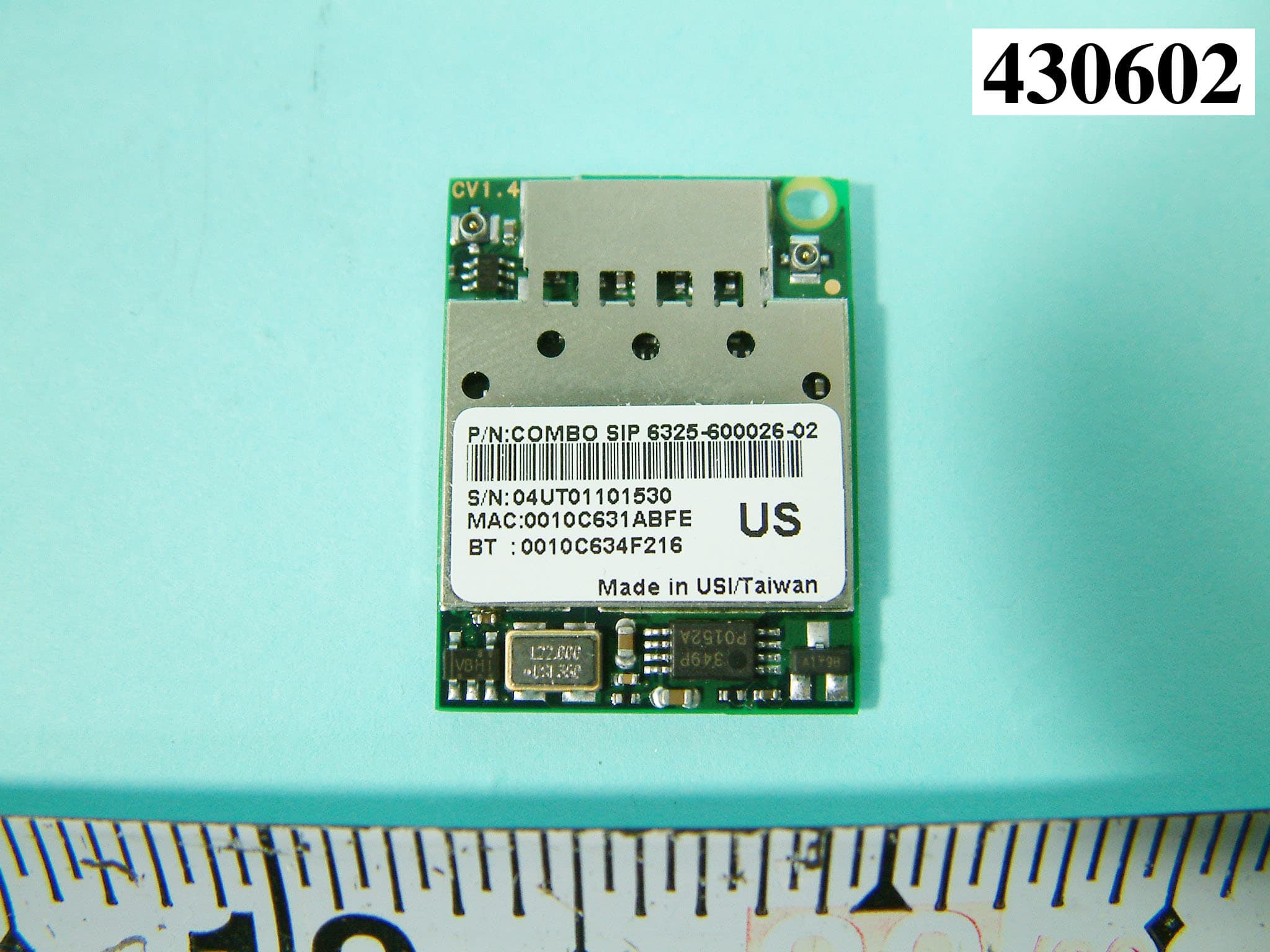
Click to zoom
Application Details
- Equipment Class
- DTS - Digital Transmission System
- Date of Grant
- Mar 17, 2004
- Application Purpose
- Original Equipment
- Date of Application
- Mar 17, 2004
- Equipment Note
- 801.11b + Bluetooth Module
- Frequency Range
- 2402.00000000 - 2480.00000000
- Country
- Taiwan
Documents & Files
Document Text
Text extracted from the exhibit documents filed with the FCC. Open a document above to read the original.
Users Manual
Federal Communication Commission Interference Statement This equipment has been tested and found to comply with the limits for a Class B digital device, pursuant to Part 15 of the FCC Rules. These limits are designed to provide reasonable protection against harmful interference in a residential installation. This equipment generates, uses and can radiate radio frequency energy and, if not installed and used in accordance with the instructions, may cause harmful interference to radio communications. However, there is no guarantee that interference will not occur in a particular installation. If this equipment does cause harmful interference to radio or television reception, which can be determined by turning the equipment off and on, the user is encouraged to try to correct the interference by one of the following measures: - Reorient or relocate the receiving antenna. - Increase the separation between the equipment and receiver. - Connect the equipment into an outlet on a circuit different from that to which the receiver is connected. - Consult the dealer or an experienced radio/TV technician for help. FCC Caution: To assure continued compliance, (example - use only shielded interface cables when connecting to computer or peripheral devices) any changes or modifications not expressly approved by the party responsible for compliance could void the user's authority to operate this equipment. This device complies with Part 15 of the FCC Rules. Operation is subject to the following two conditions: (1) This device may not cause harmful interference, and (2) this device must accept any interference received, including interference that may cause undesired operation. This device is intended only for OEM Integrators. The OEM integrator should be aware of the following important issues. Labeling of the End Product The end product integrate this module has to be clearly identified on the label that this end product contain an FCC approved RF module. The format of such statement could containTx FCC ID: IXMWM-BB-AG-01 or similar. Integration Note a) This module is authorized under limited module approval specified to mobile host equipment. So, the antenna must be installed such that 20cm is maintained between the antenna and users. b) The transmitter module may not be co-located with any other transmitter or antenna. As long as the 2 conditions above are met, further transmitter testing will not be required. However, the OEM integrator is still responsible for testing their end-product for any additional compliance requirements required with this module installed (for example, digital device emission, PC peripheral requirements, etc.) IMPORTANT NOTE: In the event that these conditions can not be met (for example certain laptop configurations, general purpose PCMCIA or similar cards, or co-location with another transmitter), then the FCC authorization is no longer considered valid and the FCC ID can not be used on the final product (including the transmitter) and obtaining a separate FCC authorization. All rights are reserved by USI. No part of this technical document can be reproduced in any form without permission of USI. 1 Features l Small size suitable for low volume system integration. l Low power consumption, extend battery life. l 2.412 – 2.484 GHz frequency band. l Support hardware signaling l Easy for integration into mobile and handheld device with flexible system configuration and antenna design. Data Sheet Feb. 2004, Rev 2.4 802.11b+Bluetooth COMBO SiP Module WM-BB-AG-01 Introduction The USI 802.11 Wireless SiP module WM-BB-AG- 01 which refers as “COMBO SiP module” is a full small size module that provides full function of 802.11b and Bluetooth class 2 on a 22*29 mm tiny module via 60 pins board to board connector. This multi- functionality and board to board physical interface provide system users the maximum flexibility including system feature and system integration. WM-BB-AG-01 is approved as one of USI embedded Wi-Fi module product lines. There are two product variants of WM-BB-AG-01 by de- populating either 802.11b or Bluetooth to be a single module which provided better cost-feature on system with single design-in effort. The small size design (22*29*3.5 mm), low power consumption (Tx 330 mA) and excellent radio performance make it the best solution which is suitable for OEM customers who require embedded 802.11b Wi-Fi plus Bluetooth features, such as, wireless PDA, barcode scanner, mini-printer, VoIP phone etc. For the hardware features, Agere 802.11 chipset solution is adopted for 802.11b, and CSR BlueCore 02-ROM for Bluetooth. Two antenna connectors provide antenna connectivity for each function. In additional to the classic radio design, physical signaling between Bluetooth and 802.11b functional block provides the best performance when Bluetooth and 802.11b function at the same time. For the software and driver development, USI provides extensive technical document and reference software code for system integration. Hardware evaluation kit and development utility will be released base on listed OS and processors to OEM customers under agreement for development. www.usi.com.tw 802.11 b + Bluetooth COMBO SiP Module v 2.4 All rights are reserved by USI. No part of this technical document can be reproduced in any form without permission of USI. 2 OEM Deliverables • WM-BB-AG-01 with packing • Test Platform includes application (PDA ), software utilities which support customers for integration, performance tests, and homologation. Temperature and Humidity . Operating Temperature 0° to 60° Celsius Non Operating Temperature -10° to 70° Celsius Humidity Range 20% to 90%( Non-condensing, relative) Voltage and Current Power supply for the WM-BB-AG-01 will be provided by the host via the board to board connector. Voltage Operating Voltage 3.3 Volt (Typ.), Max 3.6V, Min 3.15V Voltage Ripple +/- 2%(Max value not exceeding operating voltage) Current (Typical) Continuous Transmit 340 mA (Both…
Text truncated - open the document above for the full version.
Cover Letter(s)
Request Letter Subject: Limited Module Approval Date: 17 th Mar. 2004 FCC ID: IXMWM-BB-AG-01 Dear Reviewer, We, Sporton International Inc., are authorized by USI Corporation to have their state-of-the-art 802.11b and Bluetooth Module approved under limited module approval authorization. The application of this module is specified to Mobile host equipment. The requirements regulated in Public Notice DA00-1407 have been fulfilled and clearly explained below. 1. The requirement of RF shielding: The shielding of the radio portion can be demonstrated in exhibition External Photo. 2. The requirement of buffered inputs: Buffered data inputs stage has been integrated in chip N4100 3. The requirement of power supply regulation: The part number of the power regulator is PSCO152. 4. The requirements of section 15.203 and 15.204(C): The requirements of antenna connector and spurious emission have been fulfilled. Please reference the exhibition Test Report. 5. The requirement of stand-alone test configuration: Please reference exhibition Test Configuration Photo for the stand-alone test configuration. 6. The requirement of labeling: The instruction on the labeling rule of the end product has been stated in the users manual of this module. Please also see the exhibition Label Sample. 7. The requirement of compliance on specific rule or operating requirements: The required FCC rule has been fulfilled and all the instructions for maintaining compliance has been clearly stated in the Users Manual. 8. The requirement of RF exposure: Please refer exhibition RF Exposure for the compliance of RF exposure rule. Please do not hesitate to contact me for any questions of this request letter. Thank you. Regards, Dr. Alan Lane V. General Manager No. 52, Hwa Ya 1 st Rd., Hwa Ya Technology Park, Kwei-Shan Hsiang, TaoYuan Hsien, Taiwan, R.O.C. Sporton International Inc. e-mail: [email protected] Tel: +886 3 327 3456 Fax: +886 3 327 0973
Cover Letter(s)
Request Letter Subject: Limited Module Approval Date: 17 th Mar. 2004 FCC ID: IXMWM-BB-AG-01 Dear Reviewer, We, Sporton International Inc., are authorized by USI Corporation to have their state-of-the-art 802.11b and Bluetooth Module approved under limited module approval authorization. The application of this module is specified to Mobile host equipment. The requirements regulated in Public Notice DA00-1407 have been fulfilled and clearly explained below. 1. The requirement of RF shielding: The shielding of the radio portion can be demonstrated in exhibition External Photo. 2. The requirement of buffered inputs: Buffered data inputs stage has been integrated in chip N4100 3. The requirement of power supply regulation: The part number of the power regulator is PSCO152. 4. The requirements of section 15.203 and 15.204(C): The requirements of antenna connector and spurious emission have been fulfilled. Please reference the exhibition Test Report. 5. The requirement of stand-alone test configuration: Please reference exhibition Test Configuration Photo for the stand-alone test configuration. 6. The requirement of labeling: The instruction on the labeling rule of the end product has been stated in the users manual of this module. Please also see the exhibition Label Sample. 7. The requirement of compliance on specific rule or operating requirements: The required FCC rule has been fulfilled and all the instructions for maintaining compliance has been clearly stated in the Users Manual. 8. The requirement of RF exposure: Please refer exhibition RF Exposure for the compliance of RF exposure rule. Please do not hesitate to contact me for any questions of this request letter. Thank you. Regards, Dr. Alan Lane V. General Manager No. 52, Hwa Ya 1 st Rd., Hwa Ya Technology Park, Kwei-Shan Hsiang, TaoYuan Hsien, Taiwan, R.O.C. Sporton International Inc. e-mail: [email protected] Tel: +886 3 327 3456 Fax: +886 3 327 0973
Cover Letter(s)
American Telecommunications Certification Body Inc. 6731 Whittier Ave, McLean, VA 22101 March 17, 2004 RE: Universal Scientific Industrial Co, Ltd. FCC ID: IXMWM-BB-AG-01 After a review of the submitted information, I have a few comments on the above referenced Application. 1) We agree that the RF exposure is not an issue, but the FCC still requires calculations as part of the application. I have provided a sample regarding a device with 2 RF outputs, both capable of transmitting at the same time if applicable. 2) Please note that it is uncertain if the device may simultaneously transmit for both the 802.11b and bluetooth transmitters. If they will not ever transmit simultaneously when in use by the end user, please properly document the filing. If they may transmit simultaneously when in use by the end user, inter-modulation radiated testing is required, including bandedge for simulateous TX for radiated intermod. Please note that when the radios do not share an antenna, only radiated tests for simultaneous transmission is required. Only one set of worst case simultaneous transmission data is going to be requested to be submitted at this time. The test engineer should indicate the worst case condition and provide justification as to why the worst case condition was chosen. The grantee should be reminded that even though the FCC requests only one set of data, they are responsible for compliance for all modes of simultaneous transmission.. Note that information given in the users manual supports the fact that the 2 transmitters may transmit simulateously. 3) Please provide clearer external photographs. Additionally, it is recommended to show/label the photographs to clearly distinguish just the EUT. Additionally, it does not appear that photographs of the bottom of the EUT were provided as part of the external photos. Please provide. 4) Please provide clearer internal photos. Additionally, due to the nature of 2 different antennas, and the fact that each is only approved for one part of the transmitter, please clearly label the external photographs to distinguish which antennas are for use with which part of the device. 5) The schematics are not clear on the regulator(s) used for 3.3 V. Please provide further information in order to support modular approval and adjust the modular approval letter as necessary. 6) Please note that since this device is being approved as a modular device, inclusion of the DoC statement or labeling of the device for a DoC (FCC logo) is not necessary. The integrator will be responsible to test the end device for Digital device emissions or PC peripheral emissions as applicable to the end use device. Please either justify or remove the FCC logo from the product. 7) The manual mentions PCMCIA cards as a possible device that this may be integrated into. Note that a PCMCIA card is not normally considered to meet with the 20 cm requirement. Therefore the users manual should contain further detailed information to adequately caution the OEM integrator as to conditions necessary to maintain compliance. For example: This device is intended only for OEM integrators under the following conditions: a) The antenna must be installed such that 20 cm is maintained between the antenna and users, and b) The transmitter module may not be co-located with any other transmitter or antenna. As long as the 2 conditions above are met, further transmitter testing will not be required. However, the OEM integrator is still responsible for testing their end-product for any additional compliance requirements required with this module installed (for example, digital device emissions, PC peripheral requirements, etc.). IMPORTANT NOTE: In the event that these conditions can not be met (for example certain laptop configurations, general purpose PCMCIA or similar cards, or co-location with another transmitter), then the FCC authorization is no longer considered valid and the FCC ID can not be used on the final product. In these circumstances, the OEM integrator will be responsible for re-evaluating the end product (including the transmitter) and obtaining a separate FCC authorization. z Page 2March 18, 2004 8) Information in the manual mentions "Since this module is installed inside the end product, the end product should be affixed a label on visible area showing that this product contain a RF module, and also its FCC ID.". Please note that the label on the exterior of the device must not simply be labeled with "FCC ID: IXMWM-BB- AG-01", as this label denotes the device as approved (which is not the case once it is integrated). The label on any final assembled device should indicate that the approved transmitter is internal by using a format such as "Contains TX FCC ID: IXMWM-BB-AG-01" or similar. Please adjust the documentation to make this clear. 802.11b report 9) Only conducted emissions test photographs were provided. Please also provide a separate exhibit for the radiated test photographs. 10) Data for spurious emission of the 802.11 shows the same limit (74 dBuV) for both peak and average measurements. Please adjust the limit as appropriate for the average measurements. 11) Please provide information regarding the RBW/VBW settings used for radiated emissions. 12) Photographs shown in the test report for radiated emissions appear to be conducted emissions. Please review/correct as necessary. 13) Several pieces of test equipment appear to be out of calibration (2 RF cables, Receiver, Bilog Antenna). Calibration interval is stated as 1 year. Equipment this far out of calibration could shed doubts on the results obtained. Please explain/correct as necessary. 14) Power spectral density results have not been provided. Please provide. 15) FYI. For future applications, please provide plots to support band edge emissions. Bandedge measurements are a common source of error and are frequently measured improperly. Therefore plots supporting this results are typically desired. Bluetooth Report 12) Pl…
Text truncated - open the document above for the full version.
Cover Letter(s)
Hi, Tim, Sorry for my late response, the weather here like, our president election, getting un-predicted. Here is my response. 1) Done already. 2) Will be ready tonight. 3) re-submitted already. 4) re-submitted already. 5) The RD of the customer is coming back tomorrow morning, I will get back to you tomorrow. 6) Thank you. 7) re-submitted already. 8) re-submitted already. 9) really ? I saw it on section 5.5.5. 10) That is only the software error. will revised the report tonight. 11) RB=VB=1MHz for peak, RB=1MHz, VB=10Hz for average. 12) the same as (9). 13) will revise and submit to you tonight. 14) done already. 15) We did have plots on the test report. BlueTooth part 12) DTS as discussed last week. 13) discussed last week already. 14) Thank you. I have revised the test report. 16) please see section 5.6, we do have plots. 17) will revised tonight. 18) will revised tonight. 15) Understand. Thank you. Alan Page 1 of 1In 3/25/2004Printed for "Timothy R. Johnson" <[email protected]>
Cover Letter(s)
Hi, Tim, What about number 1 but without exact model name of the PDA on the grant ? Because at this moment we still have no idea about the model name of the PDA which is going to be the host. ..... So, turning back to our this project. I do think what you need to do is to put a statement on the grant that this module is specific to a PDA with 3.3VDC regulator to guarantee stable power supply for the module. Even you insist to see the detail information of the PDA, maybe I will still have some difficulty to get some for you since this PDA, as I know, is still under design. Please advice your comment. Thank you. Regards, Alan
External Photos
Bluetooth: Inverted-F Antenna Bluetooth: Inverted-F Antenna Bluetooth: Inverted-F Antenna Bluetooth: Inverted-F Antenna 802.11b: Metal Inverted-F Antenna 802.11b: Metal Inverted-F Antenna 802.11b: Metal Inverted-F Antenna 802.11b: Metal Inverted-F Antenna
ID Label/Location Info
FCC ID: IXMWM-BB-AG-01 Label Location
Internal Photos
REPORT NO. : F430602 SPORTON International Inc. PAGE NUMBER : A1 OF A6 TEL : 886-2-2696-2468 ISSUED DATE : Mar. 16, 2004 FAX : 886-2-2696-2255 APPENDIX A. Photographs of EUT REPORT NO. : F430602 SPORTON International Inc. PAGE NUMBER : A2 OF A6 TEL : 886-2-2696-2468 ISSUED DATE : Mar. 16, 2004 FAX : 886-2-2696-2255 REPORT NO. : F430602 SPORTON International Inc. PAGE NUMBER : A3 OF A6 TEL : 886-2-2696-2468 ISSUED DATE : Mar. 16, 2004 FAX : 886-2-2696-2255
Operational Description
FCC ID:IXMWM-BB-AG-01 Description of Operation EUT is a WLAN with 11 channels and Bluetooth with 79 channels. This device provided of transmitting speed 1,2,5.5,11 Mbps for WLAN and 1 Mbps for Bluetooth. The device adapts Direct Sequence Spread Spectrum (DSSS) for WLAN and Frequency Hopping Spread Spectrum modulation ( FHSS ) for Bluetooth. An embedded system can become WLAN and Bluetooth enabled by inserting the WLAN and Bluetooth RF module that interfaces to the embedded processor CompactFlash interface . The antenna is printed Antenna, With embedded system becoming WLAN and Bluetooth-enable by the modules, many wireless applications will become possible, such as: Communicate with each other wirelessly (between embedded systems, laptops, PCs, and others), including sharing or exchanges of data.
RF Exposure Info
Issued on Mar. 16, 2004 SPORTON International Inc. TEL : 886-2-2696-2468 FAX : 886-2-2696-2255 MPE TEST REPORT OET65, IEEE C95.1, RSS-102 CATEGORY: Mobile Module PRODUCT NAME: 802.11b + BlueTooth COMBO SIP FCC ID.: IXMWM-BB-AG-01 MODEL NAME: WM-BB-AG-01 APPLICANT: Universal Scientific Industrial Co., Ltd 135, Lane 351, Taiping, Sec. 1, Tsao Yuen, Nan-Tou, Taiwan, R.O.C. ISSUED BY: SPORTON INTERNATIONAL INC. 6F, No. 106, Sec. 1, Hsin Tai Wu Rd., His Chih, Taipei Hsien, Taiwan, R.O.C. Statements: The test result in this report refers exclusively to the presented test model / sample. Without written approval of SPORTON International Inc., the test report shall not be reproduced except in full. Certificate or Test Report could not be used by the applicant to claim the product endorsement by CNLA, NVLAP or any agency of U.S. government. The test equipment used to perform the test are calibrated and traceable to NML/ROC or NIST/USA. Lab Code: 200079-0 Issued on Mar. 16, 2004 SPORTON International Inc. FCC ID. : NLFBT56R-BN TEL : 886-2-2696-2468 Page No. : 2of 3 FAX : 886-2-2696-2255 Issued Date : Mar. 16, 2004 1. Introduction Radio power energy is available everywhere in our daily environment. More and more application involves radio energy, which makes RF hazard becomes more and more important to human health. International organization such as IEEE or FCC spent a lot of effort to investigate the risk of placing human body in RF energy environment and try to define a rule to limit the RF emission of the radio device for protection of human health. SAR and MPE was defined as 2 major evaluation methods for RF hazard. SAR is mainly used for RF device which could be very close to the human body, and MPE is for device not going to be carried with the human body. In short, portable device has to follow the rule of SAR and mobile one MPE. This test report is for the evaluation of MPE on Mobile device which the separation distance between the antenna and the human body, under normal use condition, is longer than 20cm. 2. MPE ( Maximum Permissible Exposure ) 2.1 Limits (A) Limits for Occupational / Controlled Exposure Frequency Range (MHz) Electric Field Strength (E) (V/m) Magnetic Field Strength (H) (A/m) Power Density (S) (mW/ cm²) Averaging Time |E|²,|H|² or S (minutes) 0.3-3.0 614 1.63 (100)* 6 3.0-30 1842 / f 4.89 / f (900 / f)* 6 30-300 61.4 0.163 1.0 6 300-1500 F/300 6 1500-100,000 5 6 (B) Limits for General Population / Uncontrolled Exposure Frequency Range (MHz) Electric Field Strength (E) (V/m) Magnetic Field Strength (H) (A/m) Power Density (S) (mW/cm²) Averaging Time |E|²,|H|² or S ( minutes ) 0.3-1.34 614 1.63 (100)* 30 1.34-30 824/f 2.19/f (180/f)* 30 30-300 27.5 0.073 0.2 30 300-1500 F/1500 30 1500-100,000 1.0 30 F = frequency in MHz Issued on Mar. 16, 2004 SPORTON International Inc. FCC ID. : NLFBT56R-BN TEL : 886-2-2696-2468 Page No. : 2of 3 FAX : 886-2-2696-2255 Issued Date : Mar. 16, 2004 2.2 MPE Calculation Method E (V/m) = d GP××30 Power Density: Pd (mW/cm²) = 377 2 E E = Electric field (V/m) P = Peak RF output power (mW) G = EUT Antenna numeric gain (numeric) d = Separation distance between radiator and human body (m) The formula can be changed to Pd = 2 377 30 d GP × ×× From the peak EUT RF output power, the minimum mobile separation distance, d=20cm, as well as the gain of the used antenna, the RF power density can be obtained. 2.3 Calculated Result Maximum power density of each transmitter. Transmitter Channel No. Antenna Gain (numeric) Peak Output Power ( mW ) Power Density (S) (mW/cm²) Limit of Power Density (S) (mW/cm²) BlueTooth Channel 00 0.98 1.762 0.00003 1 802.11b Channel 01 0.83 28.184 0.0046 1 Power Density Ratio Calculation. PDR 1 PDR 2 Sum Limit 0.00003/1 = 0.00003 0.0046/1 = 0.0046 0.00463 1.0 The sum of the power density ratio is smaller than 1.0, which fulfill the RF exposure requirement.
Test Report
FCC ID: IXMWM-BB-AG-01 Issued on Mar. 23, 2004 Report No.: F430602 SPORTON International Inc. TEL : 886-2-2696-2468 FAX : 886-2-2696-2255 FCC TEST REPORT (Intermodulation Evalutation) CATEGORY: Mobile Module PRODUCT NAME: 802.11b + Bluetooth COMBO SIP FCC ID.: IXMWM-BB-AG-01 FILING TYPE: Certification BRAND NAME: USI MODEL NAME: WM-BB-AG-01 APPLICANT: Universal Scientific Industrial Co., Ltd. 135, Lane 351, Taiping, Sec.1, Tsao Yuen, Nan-Tou, Taiwan, R.O.C. MANUFACTURER: The same as Applicant. ISSUED BY: SPORTON INTERNATIONAL INC. 6F, No. 106, Sec. 1, Hsin Tai Wu Rd., His Chih, Taipei Hsien, Taiwan, R.O.C. Statements: The test result in this report refers exclusively to the presented test model / sample. Without written approval of SPORTON International Inc., the test report shall not be reproduced except in full. Certificate or Test Report could not be used by the applicant to claim the product endorsement by CNLA, NVLAP or any agency of U.S. government. The test equipment used to perform the test are calibrated and traceable to NML/ROC or NIST/USA. Lab Code: 200079-0 FCC ID: IXMWM-BB-AG-01 Issued on Mar. 23, 2004 Report No.: F430602 SPORTON International Inc. FCC ID. : IXMWM-BB-AG-01 TEL : 886-2-2696-2468 Page No. : 1of 3 FAX : 886-2-2696-2255 Issued Date : Mar. 23, 2004 Table of Contents 1. Introduction ........................................................................................................................... 2 2. Description of the EUT .........................................................................................................2 3. Evaluation Concept ..............................................................................................................2 4. Test Method and Observation ............................................................................................. 2 FCC ID: IXMWM-BB-AG-01 Issued on Mar. 23, 2004 Report No.: F430602 SPORTON International Inc. FCC ID. : IXMWM-BB-AG-01 TEL : 886-2-2696-2468 Page No. : 2of 3 FAX : 886-2-2696-2255 Issued Date : Mar. 23, 2004 1. Introduction Except the normal EM emission nature happened on single transmitter, co-located transmitter inherently produced extra emission which is only available while multiple transmitters is operated simultaneously. Such phenomenon is called “inter-modulation”. According to FCC’s rule, emission produced from inter-modulation has to be evaluated and fulfill the limit of spurious emission. In this test report, evaluation concept as well as the result will be presented. 2. Description of the EUT This product is a module seeking for limited module approval specific to mobile host equipment. There are 2 radio functions which have been integrated together inside this module, standard bluetooth with 79 hopping channels and wireless LAN IEEE802.11b with 11 channels. Both RF solutions do not share the same antenna. BlueTooth uses printed inverted-F antenna, WLAN metal inverted-F. Both individuals has been tested according to FCC part 15 rule and found in compliance with the limit. Since this product is an module, so test feature is used to have it tested under stand-alone configuration and software is used to have both of them operated simultaneously. 3. Evaluation Concept It is very hard to tell which combination is for sure can produce maximum inter-modulation emission. But basically it should be happened on the combination of 2 carrier emissions because they are the most strong one and, under the test environment defined by FCC, constructed interference of these 2 carriers should be available. So, testing will only be carried out on such condition. 4. Test Method and Observation 3 channels of WLAN has been tested while the bluetooth is also operated on the same carrier frequencies. It is observed that the emission is quite low in 3 conditions. One of the plot has been shown below. It is convinced that all the inter-modulation emission is lower than the limit. FCC ID: IXMWM-BB-AG-01 Issued on Mar. 23, 2004 Report No.: F430602 SPORTON International Inc. FCC ID. : IXMWM-BB-AG-01 TEL : 886-2-2696-2468 Page No. : 3of 3 FAX : 886-2-2696-2255 Issued Date : Mar. 23, 2004
Test Report
FCC ID: IXMWM-BB-AG-01 Issued on Mar. 16, 2004 Report No.: F430602 SPORTON International Inc. TEL : 886-2-2696-2468 FAX : 886-2-2696-2255 FCC TEST REPORT CATEGORY: Mobile Module ( BlueTooth Part ) PRODUCT NAME: 802.11b + Bluetooth COMBO SIP FCC ID.: IXMWM-BB-AG-01 FILING TYPE: Certification BRAND NAME: USI MODEL NAME: WM-BB-AG-01 APPLICANT: Universal Scientific Industrial Co., Ltd. 135, Lane 351, Taiping, Sec.1, Tsao Yuen, Nan-Tou, Taiwan, R.O.C. MANUFACTURER: The same as Applicant. ISSUED BY: SPORTON INTERNATIONAL INC. 6F, No. 106, Sec. 1, Hsin Tai Wu Rd., His Chih, Taipei Hsien, Taiwan, R.O.C. Statements: The test result in this report refers exclusively to the presented test model / sample. Without written approval of SPORTON International Inc., the test report shall not be reproduced except in full. Certificate or Test Report could not be used by the applicant to claim the product endorsement by CNLA, NVLAP or any agency of U.S. government. The test equipment used to perform the test are calibrated and traceable to NML/ROC or NIST/USA. Lab Code: 200079-0 FCC ID: IXMWM-BB-AG-01 Issued on Mar. 16, 2004 Report No.: F430602 SPORTON International Inc. FCC ID. : HLEMS860 TEL : 886-2-2696-2468 Page No. : i FAX : 886-2-2696-2255 Issued Date : Mar. 20, 2004 Table of Contents History of this test report....................................................................................................................................ii 1. General Description of Equipment under Test.............................................................................................1 1.1. Applicant..........................................................................................................................................................................................1 1.2. Manufacturer ...................................................................................................................................................................................1 1.3. Basic Description of Equipment under Test ....................................................................................................................................1 1.4. Technical Features..........................................................................................................................................................................1 1.5 Table for Carrier Frequencies .........................................................................................................................................................2 2. Test Configuration of the Equipment under Test.........................................................................................3 2.1. Description of the Test ..........................................................................................................................................................…
Text truncated - open the document above for the full version.
Contact Information
Applicant
Martin Shih(Section Manager)
Technical Contact
Sporton International Inc.Alan Lane
[email protected]+886-3-327-3456
No. 52, Hwa Ya 1st Rd., Hwa Ya Technology Park · Kwei-Shan Hsiang, Taoyuan · Taiwan
Non-Technical Contact
Sporton International Inc.Alan Lane
[email protected]+886-3-327-3456
Test Firm
Sporton International Inc.Kathy Lin
Technical Specifications
| # | Rule Parts | Frequency Range | Power Output |
|---|---|---|---|
| 2 | 15C | 2.40 GHz - 2.48 GHz | 1.80 mW |
Other Applications from Universal Scientific Industrial Co., Ltd.
IXM-UNA-P3
Nov 21, 20133G Module
Equipment Class
PCB - PCS Licensed Transmitter
IXMMESSI-V
Sep 29, 2013LTE Module
Equipment Class
JBP - Part 15 Class B Computing Device Peripheral
IXM-UNA850
Oct 01, 2012UNA 850 module
Equipment Class
PCB - PCS Licensed Transmitter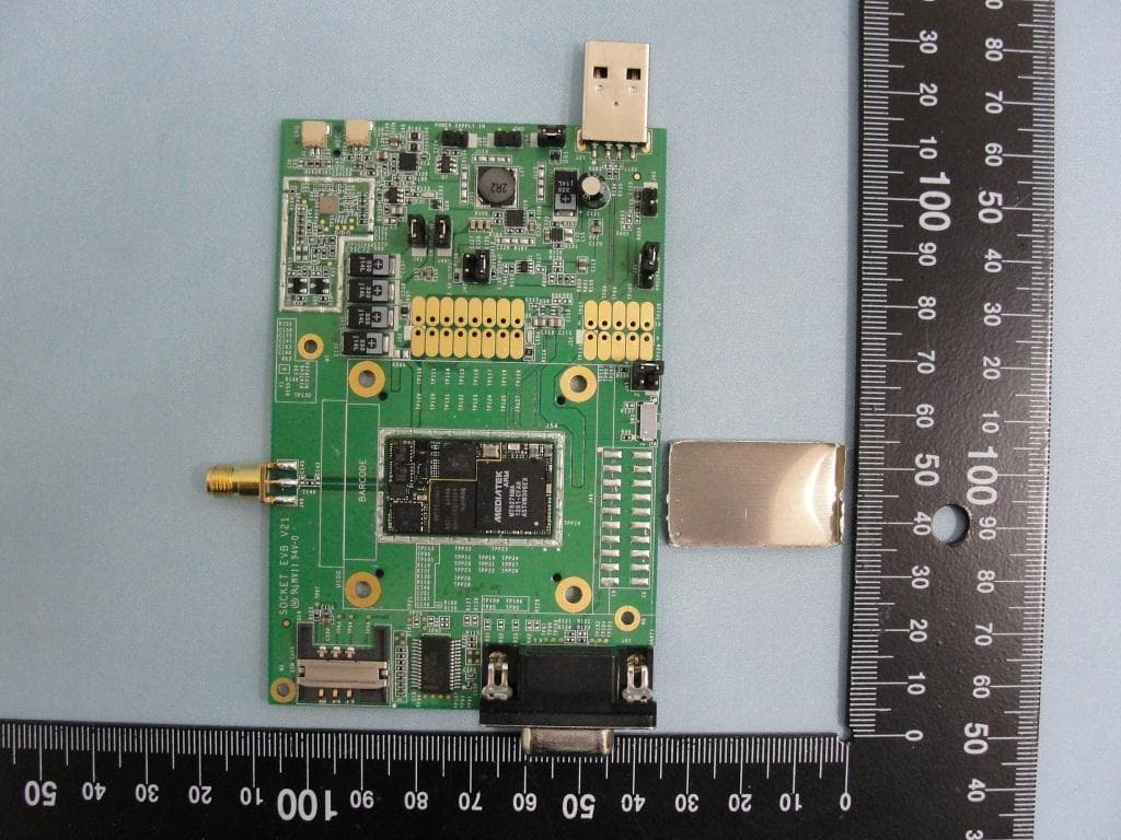
IXM-UNA900
Apr 19, 2012WWAN Module
Equipment Class
PCB - PCS Licensed Transmitter
IXMUGNAS-P3
Jul 28, 2011NETWORK ATTACHED STORAGE
Equipment Class
DTS - Digital Transmission System