J8ZBP-9000Wireless Pier to Pier Intercom
Anchor Audio Inc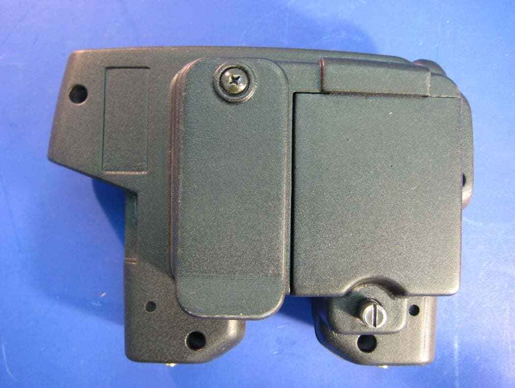
Click to zoom
Application Details
- Equipment Class
- DTS - Digital Transmission System
- Date of Grant
- Aug 09, 2010
- Application Purpose
- Original Equipment
- Date of Application
- Jul 27, 2010
- Equipment Note
- Wireless Pier to Pier Intercom
- Frequency Range
- 926.00000000 - 926.00000000
- Company
- Anchor Audio Inc
- Country
- United States
Documents & Files
Document Text
Text extracted from the exhibit documents filed with the FCC. Open a document above to read the original.
Users Manual
CONTENTS GETTING STARTED .......................................................................................................................................................... 2 WHAT IS PROLINK? .......................................................................................................................................................... 3 BELT PACKS ................................................................................................................................................................... 3 HEADSETS ...................................................................................................................................................................... 3 RECHARGEABLE BATTERIES ............................................................................................................................................. 3 BASIC OPERATION / SYSTEM RANGE ............................................................................................................................. 4,5 DEFINITIONS AND APPLICATIONS ......................................................................................................................................6 FREQUENTLY ASKED QUESTIONS ...................................................................................................................................... 7 TROUBLESHOOTING ........................................................................................................................................................ 7 TECHNICAL SPECIFICATIONS ............................................................................................................................................ 8 Anchor Audio, Inc. Portable Sound Systems • Torrance, California 100-0200-000/A - 04/10 OWNER’S MANUAL ProLink ™ WIRELESS INTERCOM SYSTEM - PATENT PENDING ANCHOR AUDIO CUSTOMER SERVICE 888/444-6077 • 310/784-2300 For videos on how to setup & use the ProLink: www.anchoraudio.com TECHNICAL SPECIFICATIONS FCC ID: J8ZBP-9000 ProLink Belt Pack (BP-9000) RF Frequency Range 902-928MHz Modulation FSK Range (line of sight) Duplex 250’ / 75 m Antenna 1/2 - wavelength dipole Power Supply 9VDC, 1.2ADC Battery Life 15 hours Weight 15oz. / 0.42kg (w/ batteries) Dimensions 4.5 x 6.25 x 3.75” / 114.3 x 158.75 x 95.25 mm Single-Ear (H-2000S & Dual-Ear Headphones H-2000) Drivers Dynamic, 40mm Impedance 300ohm +/- 15% Frequency Response 20Hz - 20kHz SPL 91dB +/- 3dB Rated Power > 40mW Distortion < 5% Microphone Dynamic, Uni-directional, Low impedance Mic Sensitivity Referenced to 0dB=1V/μbar, 1kHz Min -85 dB / Typical -83 dB / Max -81 dB Frequency Response 200Hz-12kHz Connector Plug 4-pin XLR, female Weight Single: 13 oz. / 0.37 kg & Dual: 16 oz. / 0.45 kg Warning: Changes or modifications not expressly approved by Anchor Audio, Inc. could void the user’s authority to operate this device. Only use the provided belt-clip. This device complies with part 15 of the FCC Rules. Operation is subject to the following two conditions: (1) This device may not cause harmful interference, and (2) this device must accept any interference received, including interference that my cause undesired operation. “This device has been designed to operate with a 1/2 wavelength dipole antenna with RPSMA connector, and having a maximum gain of 1.17dB. Antennas not included in this list or having a gain greater than 1.17dB are strictly prohibited for use with this device. The required antenna impedance is 50 ohms.” “To reduce potential radio interference to other users, the antenna type and its gain should be so chosen that the equivalent isotropically radiated power (e.i.r.p.) is not more than that permitted for successful communication.” “Operation is subject to the following two conditions: (1) this device may not cause interference, and (2) this device must accept any interference, including interference that may cause undesired operation of the device.” 72 A MESSAGE FROM THE OWNER Thank you for choosing an Anchor Audio wireless intercom system. Our products incorporate state-of-the-art design and the fin- est quality of materials and workmanship. We’re proud of our products and appreciate the confidence which you have shown by selecting an Anchor system. I hope you’ll take a few minutes to review this manual. We’ve incorporated several unique features into our products, and your knowledge of how to use them will enhance the performance and your enjoyment of the system. Janet Jacobs, President on behalf of all Anchor Employees GETTING STARTED Please check your new unit carefully for any damage which may have occurred during shipment. Each Anchor product is care- fully inspected at the factory and packed in specially designed boxes for safe transport. Notify the freight carrier immediately of any damage to the shipping box or product. Repack the unit in the original box and wait for inspection by the carrier’s claim agent. Notify your dealer of the pending freight claim. NOTE: All damage claims must be made with freight carrier! RETURNING SYSTEMS FOR SERVICE OR REPAIR For service or repair, please contact the dealer where system was purchased or Anchor Audio Customer Service (800/262-4671 or 310/784-2300) to obtain a RA (Return Authorization) number. All shipments to Anchor Audio must include RA number and be shipped prepaid. C.O.D. shipments will be refused and returned at your expense. Customers outside the USA must contact dealer where system was purchased for service or repair instructions. IMPORTANT: Save shipping box & packing materials, they’re specially designed to ship your unit! WARRANTY REGISTRATION & INFORMATION Please go to our website, www.anchoraudio.com, and select “Warranty Registration”. Completing this online registration form will activate your limited two-year warranty. Warranty is void if the belt pack case or headset has been opened, screws have been removed or there is evidence of tampering. Waste electrical and electronic products …
Text truncated - open the document above for the full version.
ID Label/Location Info
ProLink BP-9000M Belt Pack FCC Label 250-0318-100 February 24 , 2010 Anchor Audio, Inc. - Torrance, California Anchor Audio PATENT PENDING FCC ID: J8ZBP-9000 IC: 6631A-BP9000 M BP-9000 Made in USA
Test Report
This report contains a total of 36 pages and may be reproduced in full only. Partial reproduction may only be done with the written consent of CKC Laboratories, Inc. Anchor Audio, Inc. TEST REPORT FOR Wireless Pier to Pier Intercom, ProLink Tested To The Following Standards: FCC Part 15 Subpart C Sections: 15.209 and 15.247 Report No.: 90319‐7 Date of issue: March 16, 2010 TESTING CERT #803.01, 803.02, 803.05, 803.06 This test report bears the accreditation symbol indicating that the testing performed herein meets the test and reporting requirements of ISO/IEC 17025 under the applicable scope of EMC testing for CKC Laboratories, Inc. We strive to create long‐term, trust based relationships by providing sound, adaptive, customer first testing services. We embrace each of our customers’ unique EMC challenges, not as an interruption to set processes, but rather as the reason we are in business. Page 2of 36 Report No.: 90319‐7 TABLE OF CONTENTS Administrative Information ........................................................................................................................................... 3 Test Report Information ............................................................................................................................................ 3 Report Authorization ................................................................................................................................................. 3 Test Facility Information ............................................................................................................................................ 4 Site Registration & Accreditation Information .......................................................................................................... 4 Summary of Results ................................................................................................................................................... 5 Conditions During Testing ......................................................................................................................................... 5 Equipment Under Test ............................................................................................................................................... 5 Peripheral Devices ..................................................................................................................................................... 5 FCC Part 15 Subpart C .................................................................................................................................................... 6 Temperature And Humidity During Testing............................................................................................................... 6 15.31(e) Voltage Variation ......................................................................................................................................... 6 15.31(m) Number Of Channels .................................................................................................................................. 6 15.33(a) Frequency Ranges Tested ............................................................................................................................ 6 15.203 Antenna Requirements .................................................................................................................................. 6 EUT Operating Frequency .......................................................................................................................................... 6 15.247(a)(2) ‐6dB Bandwidth .................................................................................................................................... 7 15.247(b)(2) ‐ RF Power Output ............................................................................................................................... . 9 15.247(d) Conducted Spurious Emissions ............................................................................................................... 12 15.247(d) / 15.209/15.205 Radiated Spurious Emissions ........................................................................................ 16 15.247(e) Power Spectral Density ........................................................................................................................... 30 Band Edge ................................................................................................................................................................ 32 Supplemental Information .......................................................................................................................................... 35 Measurement Uncertainty ...................................................................................................................................... 35 Emissions Test Details .............................................................................................................................................. 35 Page 3of 36 Report No.: 90319‐7 ADMINISTRATIVE INFORMATION Test Report Information REPORT PREPARED FOR: REPORT PREPARED BY: Anchor Audio, Inc. 2565 West 237th ST Torrance, CA 90505 Dianne Dudley CKC Laboratories, Inc. 5046 Sierra Pines Drive Mariposa, CA 95338 Representative: Rohini Minapalli Project Number: 90319 Customer Reference Number: 0012528 DATE OF EQUIPMENT RECEIPT: January25, 2010 DATE(S) OF TESTING: January25 ‐March 8, 2010 Report Authorization The test data contained in this report documents the observed testing parameters pertaining to and are relevant for only the sample equipment tested in the agreed upon operational mode(s) and configuration(s) as identified herein. Compliance assessment remains the client’s responsibility. This report may not be used to claim product endorsement by A2LA or any government agencies. This test report has been authorized for release under quality control from CKC Laboratories, Inc. Ste…
Text truncated - open the document above for the full version.
Contact Information
Applicant
David Jacobs(Owner / Director of Engineering)
Technical Contact
CKC Certification Services, LLCJessina Hunter
[email protected]209-966-5240
4933 Sierra Pines Dr. · Mariposa, California · United States
Test Firm
CKC Laboratories, Inc.Steve Behm
Technical Specifications
| # | Rule Parts | Frequency Range | Power Output |
|---|---|---|---|
| 2 | 15C | 926 MHz - 926 MHz | 7.00 mW |
Other Applications from Anchor Audio Inc
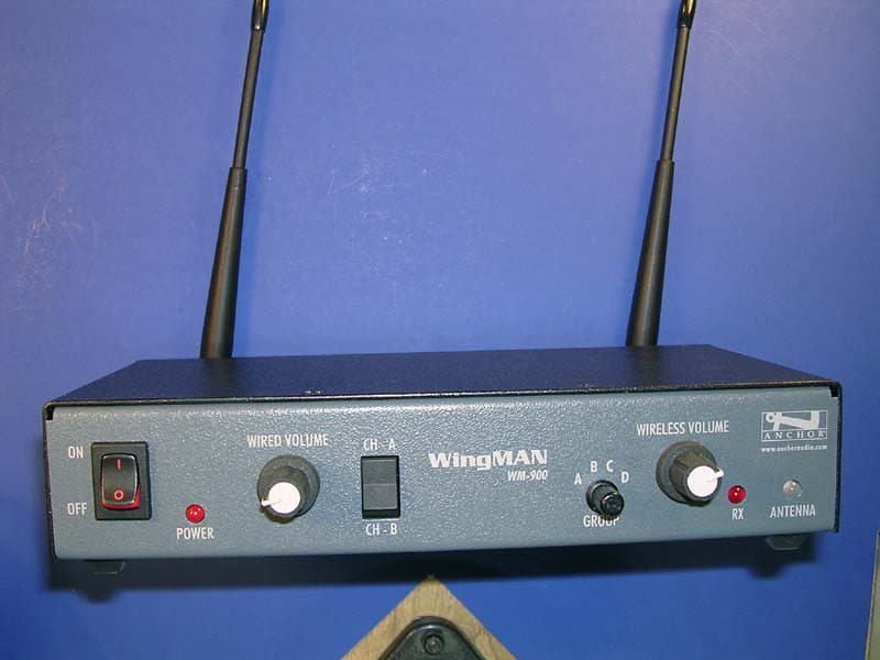
J8ZWM-900
Oct 31, 2007WingMAN
Equipment Class
TNB - Licensed Non-Broadcast Station Transmitter
J8ZBPW-300
Sep 06, 20062.4GHz Wireless Intercom
Equipment Class
DSS - Part 15 Spread Spectrum TransmitterJ8ZPB-25W
Oct 04, 1992CYY - Communications Receiver used w/Pt 15 Transmitter
Equipment Class
CYY - Communications Receiver used w/Pt 15 Transmitter