J8ZBPW-3002.4GHz Wireless Intercom
Anchor Audio Inc
Click to zoom
Application Details
- Equipment Class
- DSS - Part 15 Spread Spectrum Transmitter
- Date of Grant
- Sep 06, 2006
- Application Purpose
- Original Equipment
- Date of Application
- Aug 23, 2006
- Equipment Note
- 2.4GHz Wireless Intercom
- Frequency Range
- 2416.00000000 - 2449.00000000
- Company
- Anchor Audio Inc
- Country
- United States
Documents & Files
Document Text
Text extracted from the exhibit documents filed with the FCC. Open a document above to read the original.
Users Manual
7 WW HH AA TT II SS PP OO RR TT AA CC OO MM PP RR OO ?? PortaCom PRO is a wireless full duplex intercom system that's easy to set up and easy to use. The belt packscommunicate directly to each other via a wireless signal that can travel up to 700 feet. If there are solid obsta-cles between two belt pack users, such as a concrete wall, the range will be diminished. Two people can talk atonce into their microphones which are connected to the headsets. An unlimited number of people on 15 differ-ent channels can listen via their headsets. If a third person attempts to talk over the other two, their conversa- tion will be locked out until one of the other two stops talking. 2 AA MM EE SS SS AA GG EE FF RR OO MM TT HH EE OO WW NN EE RR Thank you for choosing an Anchor Audio wireless intercom system. Our products incorporate state-of-the-art design and the finest quality of materials and workmanship. We’re proud of our products and appreciate the confidencewhich you have shown by selecting an Anchor system.I hope you’ll take a few minutes to review this manual. We’ve incorporated several unique features into our prod-ucts, and your knowledge of how to use them will enhance the performance and your enjoyment of the system.David Jacobs, Presidenton behalf of all Anchor Employees HH EE AA DD SS EE TT OO PP EE RR AA TT II OO NN PortaCom PRO noise canceling headsets feature a dual ear piece design for maxi-mum comfort. Our headsets also include 6 pin mini-XLR gold tipped connectors,adjustable microphones and electret condenser type microphone elements.OPERATION 1. Plug the headset connector into the belt pack headset jack2. Turn on power & adjust volume on each belt pack in use3. Select a transmission channel for the group, 1 thru 16 (9 is reserved for All Call) 4. Set each belt pack in the group to the same channel5. Adjust headset boom so the microphone is located near the mouth6. Depress the PTT button to start talking, the system is voice activated GG EE TT TT II NN GG SS TT AA RR TT EE DD Please check your new unit carefully for any damage which may have occurred during shipment. Each Anchor prod-uct is carefully inspected at the factory and packed in specially designed boxes for safe transport.Notify the freight carrier immediately of any damage to the shipping box or product. Repack the unit in the origi-nal box and wait for inspection by the carrier’s claim agent. Notify your dealer of the pending freight claim. NOTE: All damage claims must be made with freight carrier! RETURNING SYSTEMS FOR SERVICE OR REPAIR For service or repair, please contact the dealer where system was purchased or Anchor Audio Customer Service(800/262-4671 or 310/784-2300) to obtain a RA (Return Authorization) number. All shipments to Anchor Audiomust include RA number and be shipped prepaid. C.O.D. shipments will be refused and returned at your expense.Customers outside the USA must contact dealer where system was purchased for service or repair instructions. IMPORTANT: Save the shipping box & packing materials, they were specially designed to ship your unit! WARRANTY REGISTRATION & INFORMATION Please go to our website (www.anchoraudio.com) and select “Warranty Registration”. Completing this online regis-tration form will activate your limited two-year warranty.Warranty is void if the belt pack case or headset has been opened, screws have been removed or there is evidenceof tampering. The case screws are tamper proof and will be damaged if you attempt to remove them. TT RR OO UU BB LL EE SS HH OO OO TT II NN GG PP OO RR TT AA CC OO MM PP RR OO CAN'T HEAR PERSON SPEAKING? Turn up the listen volume control using the thumbwheel on the side of the belt pack. If you are in an extremely loud environment, you will need to use the dual muff headsetwith noise canceling properties. If you still can't hear the person speaking, you must be out of range andneed to move closer. Check USE switches/use PTT to ensure that unit is transmitting. MICROPHONE NOT PICKING UP YOUR VOICE? First, check that you have pushed down the PTT but- ton one click and you are in active mode, note the fast flashing light. Move the mic closer to your mouthand speak up clearly. You can also adjust the VOX by turning up the mic gain knob. BACKGROUND NOISE TRANSMITTING ACROSS SYSTEM? Stay in listen mode until you are ready to speak. Then, push and hold the PTT button to ensure your system is activated only when you speak. TRANSMISSION IS WEAK? Make certain the batteries are charged by checking for the green battery light. If batteries are weak, and you need to keep going, either plug the unit into the charger and a walloutlet, or replace the rechargeable batteries with disposable alkaline batteries. PROPER INTERCOM ETIQUETTE! The PortaCom PRO is designed to handle two people speaking at once. Use proper intercom etiquette and wait to break into the conversation when the two people havestopped talking. If multiple users want to jump into and out of the conversation, use PTT (push to talk). HW-300 Dual-Earpiece Headset For a video demonstration of how to use your PortaCom PRO wireless intercom system, go to: www.anchoraudio.com/portapro.php Click on “SETUP VIDEOS” to see step-by-step instruction. CAUTION: WHEN STORING YOUR SYSTEM IN THE PORTACOM PRO HARD CASE, PLACE EACH BELT PACK INTO ITS STORAGE SLOT CAREFULLY. TURNING THE THUMB WHEEL DURING INSERTION WILL TURN THE POWER ON AND DRAIN THE BATTERY. RR EE CC HH AA RR GG EE AA BB LL EE BB AA TT TT EE RR II EE SS Each PortaCom PRO belt pack comes with two rechargeable AA NiMH batteries installed in the battery compartmentlocated on the back of the belt pack. If the LED Indicator light turns red or your transmission is becoming weak, thebatteries are low and need charging. You may continue using the belt pack while it is charging.CHARGING THE BATTERIES 1. Turn the belt pack off (you may leave system on during charging if you wish to continue use)2. Plug the included AC-300 power adapter into the jack on the side o…
Text truncated - open the document above for the full version.
Cover Letter(s)
114 OLINDA DRIVE • •• • BREA, CALIFORNIA 92823 • •• • (714) 579-0500 • •• • FAX (714) 579-1850 1: SAR: Maximum conducted RF power is given in the EMC test report as 19.97 dBm. The SAR report states the maximum conducted RF power is 19.3 dBm. The RF power at which SAR is tested must be equal to or greater than (within 5%) the power given in the EMC test report. Please explain. Response: During the test measurement, the calculation of the cable loss was not taken into account with the number inserted into the report. The cable and solder connection had a total of 0.6 dB loss. The attached revised report has the cable loss included in the conducted measurements. 2: SAR: Please include an outline of the device on the SAR area scan plots Response: The revised report attached has the outline of the device on each of the area scan plots. 3: SAR Dipole Calibration, The model number for the dipole seems to suggest a 2.45GHz dipole was used, however the system validation results indicate data at 1900 MHz. Please comment / explain. Response: This was a typographical error in the report. The system validation was conducted at 2.45 GHz, and the table was incorrectly labeled. The attached report has a revised dipole calibration report with the tables corrected. 4: SAR The EUT appears to include two transmit antennas. It appears that only one of these antennas was tested for SAR. Please comment. Response: The second antenna is for paging only. The duty cycle of the paging channel is 16us on every 3 seconds. Due to the extremely low effective power, SAR testing is not required. 5: Please provide a sample frequency hopping sequence or provide an outline of the algorithm used to select the sequence. Response: The Frequency Hopping Sequence will be uploaded along with a brief explanation of the frequency hopping sequence. 6: Please confirm that all channels are used equally on average. Response: As the hopping sequence cycles, every frequency is equally on average, resulting in even usage across the band. See the Frequency Hopping Sequence exhibit. 7: User Manual: There is no statement in the user manual regarding using only approved body worn accessories. While the device was tested at zero separation, there should still be a warning no to use a body worn accessory that would contain metal. Response: The Owner’s Manual has been revised to include a statement about body worn accessories.
Cover Letter(s)
114 OLINDA DRIVE • •• • BREA, CALIFORNIA 92823 • •• • (714) 579-0500 • •• • FAX (714) 579-1850 1: SAR: Maximum conducted RF power is given in the EMC test report as 19.97 dBm. The SAR report states the maximum conducted RF power is 19.3 dBm. The RF power at which SAR is tested must be equal to or greater than (within 5%) the power given in the EMC test report. Please explain. Response: During the test measurement, the calculation of the cable loss was not taken into account with the number inserted into the report. The cable and solder connection had a total of 0.6 dB loss. The attached revised report has the cable loss included in the conducted measurements. 2: SAR: Please include an outline of the device on the SAR area scan plots Response: The revised report attached has the outline of the device on each of the area scan plots. 3: SAR Dipole Calibration, The model number for the dipole seems to suggest a 2.45GHz dipole was used, however the system validation results indicate data at 1900 MHz. Please comment / explain. Response: This was a typographical error in the report. The system validation was conducted at 2.45 GHz, and the table was incorrectly labeled. The attached report has a revised dipole calibration report with the tables corrected. 4: SAR The EUT appears to include two transmit antennas. It appears that only one of these antennas was tested for SAR. Please comment. Response: The second antenna is for paging only. The duty cycle of the paging channel is 16us on every 3 seconds. Due to the extremely low effective power, SAR testing is not required. 5: Please provide a sample frequency hopping sequence or provide an outline of the algorithm used to select the sequence. Response: The Frequency Hopping Sequence will be uploaded along with a brief explanation of the frequency hopping sequence. 6: Please confirm that all channels are used equally on average. Response: As the hopping sequence cycles, every frequency is equally on average, resulting in even usage across the band. See the Frequency Hopping Sequence exhibit. 7: User Manual: There is no statement in the user manual regarding using only approved body worn accessories. While the device was tested at zero separation, there should still be a warning no to use a body worn accessory that would contain metal. Response: The Owner’s Manual has been revised to include a statement about body worn accessories.
Cover Letter(s)
114 OLINDA DRIVE • •• • BREA, CALIFORNIA 92823 • •• • (714) 579-0500 • •• • FAX (714) 579-1850 1: Please provide additional details regarding the second paging transmitter referenced in the last TCB reply that is used for paging. This transmitter is not mentioned in the operational description, yet is shown in the block diagram as a complete second transmitter. o Is the transmitter frequency hopping or does it operate on a single channel? Response: Yes, it is frequency hopping. o What is the transmit power? The previous reply stated the duty cycle as being 16 uS / 3S. Please confirm, is this the maximum transmit duty cycle? Is the duty cycle fixed? Response: The duty cycle is 16 uS / 3 seconds, .0000053%. This is the maximum transmit duty cycle and it is fixed. The power out of this transmitter was very low (well below that of the main transmitter). o Can the paging transmitter and the “regular” transmitter transmit at the same time? Response: The transmitters are both powered up at the same time. However, the paging transmitter does not transmit very frequently. It only transmits one “packet” every several seconds. This packet is transmitted in between packets being transmitted from the main transmitter. This means that the transmitters are not transmitting at the same instant. Since so many more packets are being sent from the transmitter, it is indistinguishable when the paging transmitter transmits. Please note during the testing both transmitters were active with the main transmitter being on a constant transmit mode for testing purposes. o What is it that will prompt the paging transmitter to transmit? Response: During normal customer operation, this occurs when the channel selector is set to channel 9. Channel 9 is the paging channel (Please note during the testing this was active as the EUT was in a special test mode). o Is the transmit power the same as the regular transmitter? Response: The transmit power is much less.
ID Label/Location Info
BB AA SS II CC SS YY SS TT EE MM OO PP EE RR AA TT II OO NN IMPORTANT : Batteries Are Shipped Fully Charged! 1. Charge installed NiMH batteries w/ included charger2. Select a transmission channel on the belt pack (1 thru 16, 9 is reserved for All Call channel) 3. Plug headset connector into jack on belt pack4. Turn on power & adjust volume w/ thumbwheel on side Slow flashing light indicates power on / Listen Only Mode 5. Press PTT button once for Active Mode6. Press & hold PTT button for Push To Talk Mode4. Set each belt pack in a group to the same channel NOTE: Repeat the steps above for each belt pack/user. AA DD JJ UU SS TT II NN GG MM II CC RR OO PP HH OO NN EE GG AA II NN Adjust the microphone sensitivity (gain level) to compensate forindividual users voice levels and surroundings. For soft voices orwhen whispering raise sensitivity, lower it if you need to shout. 1. Remove rubber plug on back of belt pack to access dial2. Using a small screwdriver turn the VOX dial clockwise to raise mic sensitivity, counterclockwise to lower 3. Replace plug to keep dirt & debris out of unit NOTE: Lower gain level if your voice sounds distorted. SS YY SS TT EE MM RR AA NN GG EE Under ideal conditions the distance between belt packs can be up to700’ line of sight. However, system performance can be affected bymany external sources. To minimize the effects of interference: • Keep the distance between belt packs as short as possible• Make sure that there are no obstructions between belt packs• Maintain visual contact with all users in the group CAUTION: Attempting to operate the PortaCom PRO through or around walls, through ceilings and/or around metal objects will reduce system range and clarity. PORTACOM PRO BELT PACK TOP & BACK VIEWModel Shown: BPW-300 Belt Pack Shown w/ Battery Compartment Cover Removed 4 ENCRYPTION SELECTION SWITCHES “ON” POSITION GAIN ADJUSTMENT HEADSET JACK (plug in headset) ALL CALL CHANNEL (set to channel 9 for All Call) LED INDICATOR - OPERATING STATUS Slow Flash: Listen Only ModeFast Flash: Active Mic Mode (talk or listen)Solid On: Transmitting/Receiving LED INDICATOR - BATTERY STATUS Green: Battery Good Red: Battery Low/Charging Error Amber: Charging Battery/All Call Mode PUSH TO TALK BUTTON Turn Unit On w/ Thumbwheel: Listen Only modeSingle-Click: Lock In Active Mic (talk or listen) Single-Click Again: Switch to Listen Only Mode Push & Hold: Push to Talk Mode UU .. SS .. EE .. (( UU SS EE RR SS EE LL EE CC TT AA BB LL EE EE NN CC RR YY PP TT II OO NN )) PortaCom PRO comes with a simple, easy to use encryption method to make certain no one can listen in on your conversations. Al l belt packs are shipped with the encryption settings in the OFF position, this allows all your belt packs to operate together out of the box. Follow the instru ctions below to enable encryption. SETTING USER ENCRYPTION NOTE: Belt packs must be powered off and on every time encryption settings are changed for proper operation. 1. Remove the battery compartment cover by sliding the door down2. Locate the opening that houses eight small selection switches (see above)3. With a small screwdriver (included) set the ON/OFF settings of the eight switches to any pattern you desire 4. Set the same ON/OFF pattern to the switches on each belt pack in the group so they can communicate with each other 5. Turn power for each belt pack off and back on the engage encryption6. Test all of the units to verify that the code has been set correctly FACTORY USE ONLY REMOVE RUBBER PLUGTO ACCESS CHANNEL SELECTOR (set to match other belt packs)
RF Exposure Info
2867 Progress Place, Suite 4D • Escondido, CA 92029 • U.S.A. TEL (760) 737-3131 • FAX (760) 737-9131 http://www.rfexposurelab.com CERTIFICATE OF COMPLIANCE SAR EVALUATION Anchor Audio, Inc. Dates of Test: July 19, 2006 2565 West 237 th Street Test Report Number: SAR.20060701 Torrance, CA 90505 Revision A FCC ID: J8ZBPW-300 IC Certificate: 6631A-BPW300 Model(s): Portacom Pro BPW-300 Test Sample: Pre-Production Unit same as Production Serial No.: Eng 1 Equipment Type: Wireless Intercom System Classification: Portable Transmitter Next to Body TX Frequency Range: 2416 - 2449 MHz Frequency Tolerance: ± 25 ppm Maximum RF Output: 19.92 dBm Conducted (10% Duty Cycle) Signal Modulation: OFDM Antenna Type (Length): Internal(Linx P/N ANT-2.45-CHP) Battery: Two AA Rechargeable Application Type: Certification FCC Rule Parts: Part 15E Industry Canada: RSS-102 This wireless mobile and/or portable device has been shown to be compliant for localized specific absorption rate (SAR) for uncontrolled environment/general exposure limits specified in ANSI/IEEE Std. C95.1-1999 and had been tested in accordance with the measurement procedures specified in IEEE 1528-2003, OET Bulletin 65 Supp. C, RSS-102 and Safety Code 6 (See test report). I attest to the accuracy of the data. All measurements were performed by myself or were made under my supervision and are correct to the best of my knowledge and belief. I assume full responsibility for the completeness of these measurements and vouch for the qualifications of all persons taking them. RF Exposure Lab, LLC certifies that no party to this application has been denied FCC benefits pursuant to Section 5301 of the Anti-Drug Abuse Act of 1988, 21 U.S.C. 853(a). Jay M. Moulton Vice President Certificate # 2387.01 © 2006 RF Exposure Lab, LLC This report shall not be reproduced except in full without the written approval of RF Exposure Lab, LLC. FCC ID: J8ZBPW-300 © 2006 RF Exposure Lab, LLC Page 2 of 63 This report shall not be reproduced except in full without the written approval of RF Exposure Lab, LLC. Table of Contents 1. Introduction........................................................................................................................... 3 SAR Definition [5]...................................................................................................................... 3 2. SAR Measurement Setup..................................................................................................... 4 Robotic System ......................................................................................................................... 4 System Hardware..................................................................................................................... 4 System Description................................................................................................................... 4 E-Field Probe ALS-E-020......................................................................................................... 5 3. Robot Specifications............................................................................................................. 7 4. Probe and Dipole Calibration................................................................................................ 8 5. Phantom & Simulating Tissue Specifications........................................................................ 9 SAM Phantom........................................................................................................................... 9 Brain & Muscle Simulating Mixture Characterization................................................................ 9 Device Holder........................................................................................................................... 9 6. Definition of Reference Points............................................................................................. 10 Ear Reference Point................................................................................................................ 10 Device Reference Points ........................................................................................................ 10 7. Test Configuration Positions............................................................................................... 11 Positioning for Cheek/Touch [5].............................................................................................. 11 Positioning for Ear / 15 ̊ Tilt [5]................................................................................................ 12 Body Worn Configurations...................................................................................................... 13 8. ANSI/IEEE C95.1 – 1999 RF Exposure Limits [2]............................................................... 14 Uncontrolled Environment....................................................................................................... 14 Controlled Environment.......................................................................................................... 14 9. Measurement Uncertainty................................................................................................... 15 10. System Validation........................................................................................................... 16 Tissue Verification................................................................................................................... 16 Test System Verification......................................................................................................... 16 11. SAR Test Data Summary................................................................................................ 17 Procedures Used To Establish Test Signal............................................................................. 17 Device Test Condition................................................................................................…
Text truncated - open the document above for the full version.
Test Report
ANCHOR AUDIO PORTACOM PSEUDORANDOM FREQUENCY HOPPING SEQUENCES 8/22/06 The Wireless Portacom uses pseudorandom frequency hopping sequences that are hard- coded into the firmware. Channels use the same set of frequencies but are hopped in different sequences. Frequencies are spaced 1MHz apart, extending from 2416MHz through 2449MHz. As the hopping sequence cycles, every frequency is equally on average, resulting in even usage across the band. Following is the list of channel hopping sequences by system channel. (in MHz) 1. 2434, 2417, 2431, 2438, 2449, 2422, 2419, 2447, 2443, 2425, 2439, 2418, 2436, 2423, 2432, 2440, 2428, 2448, 2441, 2427, 2445, 2420, 2429, 2433, 2435, 2442, 2421, 2430, 2416, 2437, 2446, 2426, 2424, 2444 2. 2442, 2440, 2418, 2447, 2437, 2422, 2441, 2417, 2425, 2432, 2427, 2446, 2423, 2436, 2435, 2430, 2433, 2444, 2419, 2424, 2431, 2449, 2443, 2448, 2421, 2434, 2420, 2429, 2438, 2416, 2426, 2428, 2439, 2445 3. 2416, 2435, 2420, 2425, 2445, 2419, 2440, 2421, 2417, 2441, 2439, 2447, 2432, 2446, 2427, 2444, 2433, 2426, 2431, 2422, 2436, 2423, 2448, 2442, 2437, 2434, 2438, 2449, 2443, 2424, 2428, 2430, 2429, 2418 4. 2418, 2443, 2440, 2432, 2421, 2431, 2448, 2427, 2433, 2442, 2419, 2435, 2438, 2449, 2425, 2444, 2446, 2416, 2437, 2426, 2445, 2430, 2429, 2428, 2423, 2424, 2420, 2434, 2441, 2447, 2436, 2417, 2422, 2439 5. 2436, 2439, 2417, 2441, 2427, 2437, 2420, 2424, 2449, 2426, 2421, 2446, 2435, 2442, 2438, 2428, 2433, 2423, 2448, 2445, 2425, 2444, 2440, 2429, 2430, 2432, 2431, 2434, 2416, 2419, 2443, 2418, 2422, 2447 6. 2425, 2429, 2427, 2430, 2421, 2443, 2423, 2438, 2437, 2436, 2446, 2428, 2440, 2448, 2426, 2422, 2447, 2416, 2434, 2445, 2420, 2419, 2444, 2417, 2432, 2424, 2441, 2439, 2442, 2433, 2449, 2435, 2431, 2418 7. 2441, 2439, 2446, 2436, 2424, 2438, 2419, 2427, 2426, 2443, 2435, 2437, 2442, 2434, 2417, 2447, 2431, 2433, 2432, 2420, 2418, 2421, 2416, 2445, 2440, 2429, 2430, 2448, 2425, 2423, 2444, 2428, 2422, 2449 8. 2444, 2431, 2420, 2422, 2433, 2428, 2424, 2436, 2438, 2442, 2427, 2448, 2423, 2432, 2425, 2441, 2440, 2418, 2421, 2443, 2449, 2429, 2435, 2434, 2430, 2447, 2437, 2439, 2416, 2445, 2446, 2419, 2417, 2426 9. 2443, 2422, 2429, 2419, 2444, 2448, 2446, 2440, 2424, 2417, 2421, 2438, 2433, 2432, 2426, 2434, 2447, 2430, 2425, 2416, 2427, 2437, 2436, 2423, 2418, 2449, 2428, 2439, 2435, 2431, 2420, 2441, 2445, 2442 10. 2427, 2421, 2417, 2445, 2446, 2440, 2432, 2422, 2436, 2428, 2431, 2443, 2423, 2447, 2439, 2424, 2416, 2435, 2430, 2437, 2444, 2426, 2449, 2434, 2425, 2418, 2429, 2442, 2420, 2438, 2448, 2433, 2419, 2441 11. 2422, 2438, 2426, 2427, 2442, 2417, 2437, 2448, 2436, 2449, 2432, 2440, 2428, 2431, 2446, 2435, 2439, 2424, 2433, 2418, 2441, 2429, 2421, 2423, 2419, 2447, 2430, 2444, 2443, 2420, 2445, 2434, 2425, 2416 12. 2423, 2420, 2447, 2421, 2424, 2438, 2446, 2435, 2448, 2426, 2436, 2431, 2449, 2427, 2442, 2425, 2432, 2417, 2430, 2437, 2419, 2434, 2428, 2444, 2439, 2443, 2429, 2422, 2440, 2416, 2441, 2433, 2445, 2418 13. 2429, 2444, 2417, 2440, 2416, 2446, 2434, 2445, 2418, 2423, 2433, 2437, 2419, 2448, 2438, 2425, 2441, 2430, 2443, 2439, 2427, 2431, 2428, 2442, 2435, 2436, 2426, 2449, 2420, 2424, 2447, 2432, 2421, 2422 14. 2416, 2424, 2444, 2442, 2443, 2438, 2417, 2439, 2448, 2418, 2446, 2420, 2445, 2423, 2434, 2430, 2426, 2436, 2427, 2433, 2419, 2435, 2431, 2437, 2440, 2441, 2432, 2428, 2449, 2422, 2447, 2421, 2425, 2429 15. 2432, 2442, 2427, 2421, 2418, 2449, 2436, 2437, 2428, 2447, 2438, 2446, 2434, 2417, 2416, 2420, 2435, 2423, 2441, 2444, 2431, 2425, 2419, 2439, 2440, 2422, 2448, 2424, 2433, 2429, 2445, 2426, 2443, 2430 16. 2449, 2446, 2437, 2421, 2435, 2418, 2442, 2424, 2436, 2428, 2425, 2447, 2440, 2427, 2434, 2432, 2429, 2431, 2416, 2422, 2445, 2441, 2438, 2430, 2433, 2417, 2439, 2448, 2419, 2423, 2420, 2443, 2426, 2444
Test Report
Ref Lvl 117 dB V Ref Lvl 117 dB V RBW 1 MHz VBW 1 MHz SWT 5 ms RF Att 30 dB A IN1 Unit dB V Center 2.416 GHz500 s/ TDS 1VIEW1AP 29.Jun 2006 17:18 20 30 40 50 60 70 80 90 100 110 17 117 1 1 Delta 1 [T1] -28.26 dB 370.741483 s 1 [T1] 77.38 dB V 2.975952 ms 1 [T1] -28.26 dB 370.741483 s D1 74 dB V D2 54 dB V Date: 29.JUN.2006 17:18:08 Time of One Pulse is 370.741483 uS Ref Lvl 117 dB V Ref Lvl 117 dB V RBW 1 MHz VBW 1 MHz RF Att 30 dB A IN1 Unit dB V TDS SWT 200 ms Center 2.416 GHz20 ms/ 1VIEW1AP 29.Jun 2006 17:20 20 30 40 50 60 70 80 90 100 110 17 117 1 1 Delta 1 [T1] 1.16 dB 100.200401 ms 1 [T1] 52.14 dB V 17.234469 ms 1 [T1] 1.16 dB 100.200401 ms D1 74 dB V D2 54 dB V Date: 29.JUN.2006 17:20:53 Number of Pulses in 100 mS = 3 Ref Lvl 117 dB V Ref Lvl 117 dB V RBW 1 MHz VBW 1 MHz RF Att 30 dB A IN1 Unit dB V 29.Jun 2006 17:21 TDS SWT 100 ms Center 2.416 GHz10 ms/ 1VIEW1AP 20 30 40 50 60 70 80 90 100 110 17 117 11 Delta 1 [T1] 0.00 dB 0.000000 s 1 [T1] 52.53 dB V 10.000000 ms 1 [T1] 0.00 dB 0.000000 s D1 74 dB V D2 54 dB V Date: 29.JUN.2006 17:21:43 View 2 showing the number of pulses per 100 mS is 3 Total Duty Cycle = 370.741483 uS * 3 = 1.112 mS = 1.112 % The maximum 20 dB peak to average can be taken.
Test Report
Revised 5/2/03 Any 2.4GHz Wireless Product Including: ■Bluetooth ■802.11 ■ZigBee ■Wireless PCMCIA Cards ■Telemetry ■Data Collection ■Industrial Process Monitoring ■Compact Wireless Products ■External Antenna Elimination APPLICATIONS ■Incredibly Compact SMD Package ■Superior LTCC Technology ■50ΩCharacteristic Impedance ■Low Loss ■Wide Bandwidth ■Favorable Linear Polarization ■> Unity Gain ■No External Matching Required ■Highly Stable Over Temp. and Humidity ■Fully Hand- and Reflow-Assembly Compatible ■Cost-Effective FEATURES The exciting ANT-2.45-CHP is of the one of the world’s smallest, high-performance 2.4 Ghz Chip Antennas. It is ideal for all 2.4GHz applications including Bluetooth, 802.11, home RF, ZigBee and other popular and emerging standards. The antenna uses an advanced multilayer LTCC Technology and a proprietary hybrid spiral element to achieve size and performance characteristics superior to other designs. The incredibly compact SMD package measures a mere 6.5mm (L) x 2.2mm (W) x 1.0mm (H) and is fully compatible with hand- and reflow- attachment processes. The antenna's favorable electrical specifications, stability and cost- effectiveness make it the logical choice for a wide variety of applications. ANT-2.45-CHP-x DESCRIPTION 0.4mm 1.0mm 6.5mm 2.2mm 2.4 PHYSICAL DIMENSIONS PART#DESCRIPTION ANT-2.45-CHP-x2.45GHz Ultra-Compact Chip Antenna x= "T" for Tape/Reel, "B" for Bulk Standard Reel is 3,000 pcs. Quantities less than 3,000 pcs. supplied in Bulk. ORDERING INFORMATION 2.45GHz ULTRA COMPACT CHIP ANTENNA DATA GUIDE 0.040" 0.100" 0.260" Actual Size Pad Layout Page 2 Dimensions6.5 x 2.2 x 1.0 Operating Temperature-25~85°C ConstructionLTCC PHYSICAL SPECIFICATIONS PolarizationLinear Operating Frequency2,400~2,488 Center Frequency2,450 MHz Bandwidth180.0 MHz Maximum Gain0.8dBi Impedance50Ω ELECTRICAL PERFORMANCE -40 -30 -20 -10 0 0 30 60 90 120 150 180 210 240 270 300 330 -40 -30 -20 -10 0 [deg.] dB E_pl.(y-x) H_pl.(x-z) ref Dipole x z y 2.4 SPECIFICATIONS CHARACTERISTICS Impedance Radiation Pattern Return Loss Page 3 REFLOW SOLDERING PROFILE FLOW SOLDERING PROFILE 230 °C 200 °C 150 °C 60sec min 20sec min preheating 100sec max soldering 10sec max cooling 60sec min 235 ¡C 150 ¡C 60sec min preheating 100sec dipping 2 ±0.5sec cooling 60sec min SOLDERING CONSIDERATIONS Hand Soldering This antenna is designed for high-volume automated assembly, however, it may be successfully attached by hand assembly techniques. A hand-solder temperature of 225° or lower should be used. Do not exceed a 10 sec. heating …
Text truncated - open the document above for the full version.
Contact Information
Applicant
David Jacobs(Owner / Director of Engineering)
Technical Contact
Compatable ElectronicsKyle Fujimoto
[email protected]714 579 0500
114 Olinda Drive · Brea, California · United States
Test Firm
Compatible Electronics, Inc.Michael Christensen
Technical Specifications
| # | Rule Parts | Frequency Range | Power Output |
|---|---|---|---|
| 1 | 15C | 2.42 GHz - 2.45 GHz | 99.31 mW |
Other Applications from Anchor Audio Inc
J8ZBP-9000
Aug 09, 2010Wireless Pier to Pier Intercom
Equipment Class
DTS - Digital Transmission System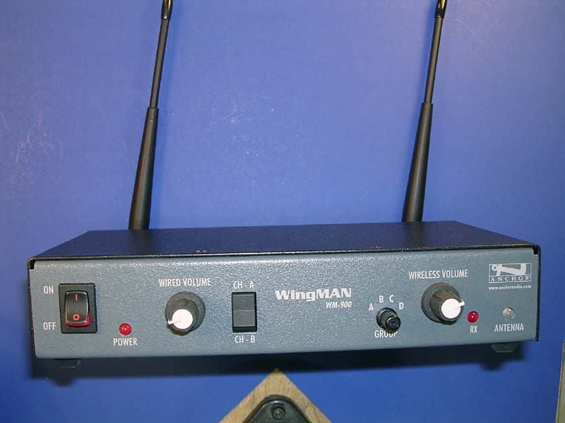
J8ZWM-900
Oct 31, 2007WingMAN
Equipment Class
TNB - Licensed Non-Broadcast Station TransmitterJ8ZPB-25W
Oct 04, 1992CYY - Communications Receiver used w/Pt 15 Transmitter
Equipment Class
CYY - Communications Receiver used w/Pt 15 Transmitter