J8ZWM-900WingMAN
Anchor Audio Inc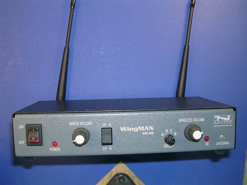
Click to zoom
Application Details
- Equipment Class
- TNB - Licensed Non-Broadcast Station Transmitter
- Date of Grant
- Oct 31, 2007
- Application Purpose
- Original Equipment
- Date of Application
- Oct 28, 2007
- Equipment Note
- WingMAN
- Frequency Range
- 945.00000000 - 951.00000000
- Company
- Anchor Audio Inc
- Country
- United States
Documents & Files
Document Text
Text extracted from the exhibit documents filed with the FCC. Open a document above to read the original.
Users Manual
A MESSAGE FROM THE OWNER Thank you for choosing an Anchor Audio intercom system. Our products incorporate state-of-the-art design and the finest quality of materials and workmanship. We’re proud of our products and appre-ciate the confidence which you have shown by selecting an Anchor system.I hope you’ll take a few minutes to review this manual. We’ve incorporated several unique features into our products, and your knowledge of how to use them will enhance the performance and your enjoyment of the system.Janet Jacobs – Presidenton behalf of all Anchor Employees Anchor Audio, Inc.Portable Sound Systems • Torrance, California 100-0165-000/A - 10/07 OWNER’S MANUAL WINGMANINTERCOM ADAPTOR WINGMAN TECHNICAL SPECIFICATIONS Range (line of sight) 1,500’ / 450 m FCC License User Registration Selectable Wireless Groups 4 Selectable Wired Channels 2 Frequency 944 – 952 MHz Frequency Settings 4 per Group Output Power 8 dBm DC Requirements 9V – 0.5A Interface Connector 3-pin female XLR Antenna 1/2 wave length dipole Antenna Length 7.2” / 182 mm Dimensions 8.5 x 4.5 x 1.7 in / 21.6 x 11.4 x 4.32 cm Weight 2.4lbs / 1.1kg FCC ID: J8ZWM-900 (Specifications subject to change without notice) NEED MORE HELP? View demonstration videos on proper WingMAN setup & operation – www.anchoraudio.com/wingman.php GETTING STARTED Please check your new unit carefully for any damage which may have occurred during shipment. Each Anchor product is carefully inspected at the factory and packed in specially designed boxes for safe transport.Notify the freight carrier immediately of any damage to the shipping box or product. Repack the unit in the original box and wait for inspection by the carrier’s claim agent. Notify your dealer of the pending freight claim. NOTE: All damage claims must be made with freight carrier! RETURNING SYSTEMS FOR SERVICE OR REPAIRFor service or repair, please contact the dealer you purchased your system from or Anchor Audio Customer Service at (888) 444-6077 to obtain a RA (Return Authorization) number. All shipments to Anchor Audio must include an RA number and must be shipped prepaid. C.O.D. shipments will be refused and returned at your expense. IMPORTANT: Save the shipping box & packing materials, they were specially designed to ship your unit! WARRANTY REGISTRATIONVisit our website at www.anchoraudio.com and select “War-ranty Registration”. Complete the online form to activate the two-year limited warranty on your WingMAN. TROUBLESHOOTING? INTERFERENCE IN ANCHORMAN HEADSETS?Switch your belt pack settings to a different AnchorMAN USER GROUP: A, B, C or D.BACKGROUND NOISE TRANSMITTING ACROSS SYSTEM?Reduce the headset microphone sensitivity level. Adjust the AnchorMAN mic sensitivity with the +/– Microphone but-tons on the belt pack.TRANSMISSION IS WEAK?Your rechargeable batteries may be running low. If batteries are weak, the Group LED’s will slowly flash. Your belt pack needs to be recharged. If you need to keep working, you can use disposable alkaline batteries.PROPER INTERCOM ETIQUETTEWingMAN is an interface station that allows full duplex com-munication between AnchorMAN belt packs and unbalanced party-line intercom systems. Use proper intercom etiquette – wait to break into the conversation network until the other system users have stopped speaking. ANCHOR AUDIO CUSTOMER SERVICE 888-444-6077 PIN CONFIGURATION The WingMAN interface connector uses a 3-pin XLR jack on the back panel. Connect the inter-face box with the wired intercom system using the 3 pin XLR jack on the rear panel.Pin ConfigurationSelect Wired Channel (A or B) to be used according to the pin description above (also shown on pack panel). The Wired Channel Switch matches the Anchor Audio PortaCOM belt pack channels. WHAT IS WINGMAN?WingMAN is an interface station that allows full duplex communication be-tween AnchorMAN belt packs and unbalanced party-line intercom systems.The WingMAN includes a transceiver that operates in a FDMA format which is compatible with AnchorMAN belt packs. An integrated interface circuit makes it possible to easily interface the transceiver with party-line intercom systems.This allows users to easily switch communications between one of the four An-chorMAN groups and one of two party line groups.ANTENNA PLACEMENTIn order to maximize system range/performance the WingMAN is designed with dual antennas. Generally, the greater the antenna separation the better WingMAN will perform. After connecting both antennas adjust their positions until Strong signal quality is indicated by the ANTENNA LED.The ANTENNA LED shows range/signal quality based on antenna separation: RED = Weak Signal / Green = Strong Signal For increased range and better signal quality mount antennas using the op-tional Antenna Mounting Kit (includes cables & mounting hardware) to achieve maximum separation. We recommend a minimum of 10’ between antennas . BASIC SYSTEM OPERATION 1. Attach supplied antennas to the “RX” & “TX” back panel jacks.2. Connect your wired intercom system to the 3-pin XLR back panel jack “INTERFACE”. 3. Connect DC power supply.4. Set DIP Switch #4 to designate wired intercom system. DIP Switch #4 Settings: ON (DOWN) – 100 ohm systems (Anchor Audio PortaCOM) OFF (UP) – 200 ohm systems (Clearcom or RTS) 5. ANCHOR AUDIO PORTACOM USERS ONLY: Select wired channel according to PIN CONFIGURATION on back panel. 6. Set GROUP knob to the AnchorMAN belt packs GROUP.7. Turn the WingMAN power switch to ON.8. Adjust WIRED & WIRELESS VOLUME to desired listening levels. NOTE: AnchorMAN belt packs assigned to the same Group & Frequency as the WingMAN will experience interference when transmitting. WINGMAN FRONT/BACK PANELSModel Shown: WM-900 DIP SWITCHESUSER ID Selection – DIP Switches 1 & 2WingMAN uses one of four GROUP/USER IDs to communicate with the AnchorMAN. Select a USER ID (1 – 4) by setting DIP Switches 1 & 2 on the back panel:AnchorMAN belt packs with the same GROUP & USER ID setting may experience significant transmissio…
Text truncated - open the document above for the full version.
Cover Letter(s)
The items listed below represent requests for infor mation following review of this application for cer tification under United States (FCC) regulations. . Further question may arise pending review of responses to t hese items. OK # Non-Conformity or Comment Submitted Response Respondent / Date of Response X 1 The second pages (those Identified as “page2”) of all operational description / technical description exhibits appear to be truncat ed. Please provide updated copies of these pages. In total there are three ex hibits which need modification. Response: There is no text missing from the page 2 of the exhibits. It was just scanned from the corner. CKC Labs 10/26/07 X 2 The DC voltage and current supplied appears onl y to refer to the unit's DC input power. This is not the intent of the section . Please provide the dc voltages applied to and dc currents into the severa l elements of the final radio frequency amplifying device for normal operation ov er the power range in accordance with 2.1033(c)(8). Response: DC voltage applied to the driver amplifier in RF section: 5VDC, Max current is 300mADC. CKC Labs 10/26/07 X 3 In the technical descriptin file entitled, “FCC WM-900 Gen Info Pg_1.pdf” the section for 2.1033(c)(3) includes a statement t hat the device is designed for permanent installation. Since this equipment d oes not have any mechanical devices for permanent attachement (such as outdoor pole mounted provisions or external mount bolt-holes) th is device should not be classified as permanently installed. The requireme nt for 2.1033(c)(3) is to provide a users manual or installation manual as ap propriate to satisfy this requirement. Response: As for being permanently mounted, there is a rackmount mounting kit that attaches to the sides of the unit. This in turn allows the unit to be "rackmounted" with other audio equipment. The second application is to put rubber feet on the unit and place it on a table. Our definition of "permanent" is simply that the unit can not be carried around while in use. It's RF performance depends on optimal antenna positioning as indicated by the front panel LED. Moving the unit around will negate the antennas' effectiveness. CKC Labs 10/26/07 X 4 The equipment class provided is TNE, “Licensed Non-Broadcast Transmitter Held to Ear” however the external photos of the equ ipment seem to indicate that the equipment is a base station. Please confi rm whether TNB, “Licensed Non-Broadcast Station Transmitter” Response: The equipment class should be TNB. Please correct the application. CKC Labs 10/26/07 x 5 The measurement procedures documented on page 3 of the test report indicate TIA/EIA, but no other reference. Was the testing p erformed in accordance Response: Yes, the testing was performed in accordance with CKC Labs 10/26/07 with TIA/EIA 603-D? TIA/EIA 603-D. x 6 Please be advised that the address on file for the FCC Grantee Code differs from that listed in the CORES FRN database. It is the responsibility of the applicant to update this information should any con tact information change. No response necessary to this item. None required. N/A
External Photos
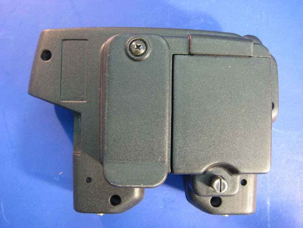
Front Back Top Bottom Left Right
Internal Photos
EUT Exposed EUT Expsoed RF Shield Removed Controller Section PCB Top PCB Bottom Transmitter xtal Transmitter Section Receiver Section Receiver xtal
Test Report
Page 1 of 54 Report No.: FC07-092 ANCHOR AUDIO, INC. TEST REPORT FOR THE WIRELESS INTERCOM, WM-900 FCC PART 74 & PART 15 SUBPART B SECTIONS 15.107 AND 15.109 CLASS B TESTING DATE OF ISSUE: OCTOBER 23, 2007 PREPARED FOR: Anchor Audio, Inc. 2565 West 237th Street Torrance, CA 95050 PREPARED BY: Mary Ellen Clayton CKC Laboratories, Inc. 5046 Sierra Pines Drive Mariposa, CA 95338 P.O. No.: 0008114 W.O. No.: 87111 Date of test: October 17-19, 2007 Report No.: FC07-092 This report contains a total of 54 pages and may be reproduced in full only. Partial reproduction may only be done with the written consent of CKC Laboratories, Inc. The results in this report apply only to the items tested, as identified herein. Page 2 of 54 Report No.: FC07-092 TABLE OF CONTENTS Administrative Information .............................................................................................3 Approvals .........................................................................................................................3 Conditions During Testing...............................................................................................3 Equipment Under Test (EUT) Description ......................................................................4 Equipment Under Test .....................................................................................................4 Peripheral Devices ...........................................................................................................4 Temperature and Humidity During Testing.....................................................................5 FCC 2.1033(c)(3) User’s Manual ....................................................................................5 FCC 2.1033(c)(4) Type of Emissions ..............................................................................5 FCC 2.1033(c)(5) Frequency Range................................................................................5 FCC 2.1033(c)(6) Operating Power.................................................................................5 FCC 2.1033(c)(7) Maximum Power Rating ....................................................................5 FCC 2.1033(c)(8) DC Voltages .......................................................................................5 FCC 2.1033(c)(9) Tune-Up Procedure ............................................................................5 FCC 2.1033(c)(10) Schematics and Circuitry Description..............................................5 FCC 2.1033(c)(11) Label and Placement ........................................................................5 FCC 2.1033(c)(12) Submittal Photos ..............................................................................5 FCC 2.1033(c)(13) Modulation Information ...................................................................5 FCC 15.107 – AC Conducted Emissions.........................................................................6 FCC 15.109 – Radiated Emissions – ...............................................................................13 FCC 2.1033(c)(14)/2.1047(b) - Audio Frequency Response...........................................32 FCC 2.1033(c)(14)/2.1047(b) - Modulation Limiting Response.....................................34 FCC 2.1033(c)(14)/2.1046/74.861(d)(1) - RF Power Output..........................................36 FCC 2.1033(c)(14)/2.1049(i)/74.861(d)(3) - Occupied Bandwidth ................................37 FCC 74.861(d)(3) - Bandedge .........................................................................................39 FCC 2.1033(c)(14)/2.1051/74.861(d)(3) - Spurious Emissions at Antenna Terminal ....41 FCC 2.1033(c)(14)/2.1053/74.861(d)(3) - Field Strength of Spurious Radiation ...........45 FCC 2.1033(c)(14)/2.1055(d)(1)- Frequency Stability & FCC 2.1055(d)(2) – Voltage Variation ..........................................................................................................................53 Page 3 of 54 Report No.: FC07-092 ADMINISTRATIVE INFORMATION DATE OF TEST: October 17-19, 2007DATE OF RECEIPT: October 17, 2007 REPRESENTATIVE: Tony Morgan MANUFACTURER: Anchor Audio, Inc. 2565 West 237th Street Torrance, CA 95050 TEST LOCATION: CKC Laboratories, Inc. 110 Olinda Place Brea, CA 92823 FREQUENCY RANGE TESTED: 9 kHz-10 GHz TEST METHOD: ANSI C63.4 (2003) and TIA/EIA PURPOSE OF TEST: To perform the testing of the Wireless Intercom, WM-900 with the requirements for FCC Part 74 & Part 15 Subpart B Sections 15.107 and 15.109 Class B devices. APPROVALS Steve Behm, Director of Engineering Services QUALITY ASSURANCE:TEST PERSONNEL: Joyce Walker, Quality Assurance Administrative Manager Eddie Wong, EMC Engineer CONDITIONS DURING TESTING No modifications to the EUT were necessary during testing. Page 4 of 54 Report No.: FC07-092 EQUIPMENT UNDER TEST (EUT) DESCRIPTION The customer declares the EUT tested by CKC Laboratories was representative of a production unit. EQUIPMENT UNDER TEST Wireless Intercom Manuf: Anchor Audio, Inc. Model: WM-900 Serial: NA FCC ID: pending Power Supply Manuf: UMEC Model: UP0151D-06P Serial: CH42Q852 PERIPHERAL DEVICES The EUT was tested with the following peripheral device(s): Function Generator Manuf: HP Model: 3312A Serial: US36023090 Page 5 of 54 Report No.: FC07-092 TEMPERATURE AND HUMIDITY DURING TESTING The temperature during testing was within +15°C and + 35°C. The relative humidity was between 20% and 75%. FCC 2.1033(c)(3) USER’S MANUAL The necessary information is contained in a separate document. FCC 2.1033 (c)(4) TYPE OF EMISSIONS F3E FCC 2.1033 (c)(5) FREQUENCY RANGE 945 MHz – 951 MHz. FCC 2.1033 (c)(6) OPERATING POWER 0.00558 Watts FCC 2.1033 (c)(7) MAXIMUM POWER RATING 1 Watt FCC 2.1033 (c)(8) DC VOLTAGES The necessary information is contained in a separate document. FCC 2.1033 (c)(9) TUNE-UP PROCEDURE The necessary information is contained in a separate document. FCC 2.1033(c)(10)SCHEMATICS AND CIRCUITRY DESCRIPTION The necessary …
Text truncated - open the document above for the full version.
Contact Information
Applicant
David Jacobs(Owner / Director of Engineering)
Technical Contact
CKC Laboratories, Inc.Mary Ellen Clayton
[email protected]209-966-5240
5046 Sierra Pines Dr. · Mariposa · United States
Test Firm
CKC Laboratories, Inc.Steve Behm
Technical Specifications
| # | Rule Parts | Frequency Range | Power Output | Emission | Tolerance |
|---|---|---|---|---|---|
| 1 | 74 | 945 MHz - 951 MHz | 5.58 mW | 144KF3E | 0.0010400000 % |
Other Applications from Anchor Audio Inc
J8ZBP-9000
Aug 09, 2010Wireless Pier to Pier Intercom
Equipment Class
DTS - Digital Transmission System
J8ZBPW-300
Sep 06, 20062.4GHz Wireless Intercom
Equipment Class
DSS - Part 15 Spread Spectrum TransmitterJ8ZPB-25W
Oct 04, 1992CYY - Communications Receiver used w/Pt 15 Transmitter
Equipment Class
CYY - Communications Receiver used w/Pt 15 Transmitter