JAKFG3CAR DATA LOGGER-MODULAR FLEET GATE
Roseman Engineering Ltd.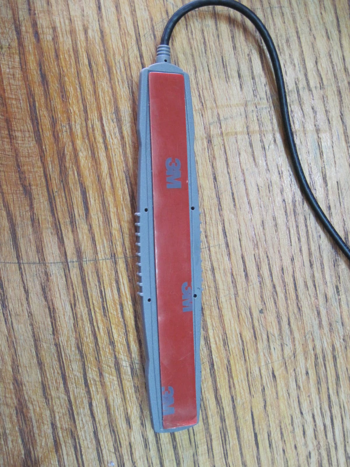
Click to zoom
Application Details
- Equipment Class
- DSS - Part 15 Spread Spectrum Transmitter
- Date of Grant
- Dec 03, 2013
- Application Purpose
- Original Equipment
- Date of Application
- Dec 03, 2013
- Equipment Note
- CAR DATA LOGGER-MODULAR FLEET GATE
- Frequency Range
- 2408.00000000 - 2480.00000000
- Company
- Roseman Engineering Ltd.
- Country
- Israel
Documents & Files
Document Text
Text extracted from the exhibit documents filed with the FCC. Open a document above to read the original.
Users Manual
FuelFocus® FMS System Diary Vehicle Subsystem Modular Fleet Journal Type 3 (FG3) #RID-FG3-01-AW Installation Manual Version 1.0 October 2013 AssetWorks, Inc. 998 Old Eagle School Road, Suite 1215 Wayne, PA 19087 Telephone: 610.225.8350 Facsimile: 610.971.9447 www.assetworks.com Copyright © 2012, AssetWorks, Inc. All Rights Reserved. 998 Old Eagle School Road, Suite 1215 | Wayne, Pennsylvania 19087 | T: 610.687.9202 | F: 610.971.9447 | www.assetworks.com 2 Table of Contents Table of Contents ..................................................................................................................... 2 1 Introduction .............................................................................................................................. 4 1.1 Purpose ............................................................................................................................ 4 1.2 System Overview .............................................................................................................. 4 1.3 Components Overview ...................................................................................................... 4 1.4 Required Tools ................................................................................................................. 6 1.5 Required Materials ............................................................................................................ 6 1.6 Wiring Instructions ............................................................................................................ 6 2 Installation ................................................................................................................................ 7 2.1 FG3 Mounting Location Considerations ............................................................................ 7 2.2 Mount the FG3 .................................................................................................................. 8 2.3 Mount the RF Antenna ...................................................................................................... 9 2.4 Connect the FG3 to the Battery or Power Source ........................................................... 10 2.5 Connect the FG3 to Ground ............................................................................................ 10 3 Wiring the Dual Input Pulse Vehicles ..................................................................................... 11 3.1 Locating the Vehicle Speed Sensor (VSS) ...................................................................... 11 3.2 Connect the Data Interface to the FG3 ............................................................................ 11 4 Wiring the CAN Bus Vehicles ................................................................................................. 15 4.1 Connect the Ignition Switch to the FG3 ........................................................................... 15 4.2 Connect the Data Interface to the FG3 ............................................................................ 15 5 Wiring the J1708 Vehicles ...................................................................................................... 19 5.1 Connect the Ignition Switch to the FG3 ........................................................................... 19 5.2 Connect the Data Interface to the FG3 ............................................................................ 19 6 Completion of Installation ....................................................................................................... 22 6.1 Verify Installation ............................................................................................................ 22 6.2 Post Installation Steps .................................................................................................... 22 7 Appendixes ............................................................................................................................ 23 7.1 Appendix A –Capturing vehicle data ............................................................................... 23 7.2 Appendix B – CAN Bus Data Connectors ....................................................................... 26 7.3 Appendix C – J1708 Data Connectors ............................................................................ 29 7.3.1 SAE J1708 Data Interface Cables ............................................................................ 29 Option 1: SAE J1708 Model 1708CAB9 ................................................................................. 29 Option 2: SAE J1708 Model 1708CAB ................................................................................... 29 7.4 The FCC Wants You to Know ......................................................................................... 30 998 Old Eagle School Road, Suite 1215 | Wayne, Pennsylvania 19087 | T: 610.687.9202 | F: 610.971.9447 | www.assetworks.com 3 AssetWorks Inc. cannot guarantee the RF Vehicle ID Box installation techniques discussed herein are complete and effective on every make, model and year of vehicle and equipment now in the marketplace or coming in the future. At times vehicle manufacturers make changes to the engine computer, wiring and/or electronics with new model years and in fact also during mid-year production. After market accessories may also impact the installation of the RF Vehicle ID Box. AssetWorks provides updates as soon possible after discovering installation challenges, new OBD types or anything effecting proper operation. We request feedback from the many very knowledgeable Automotive Technicians working with this technology. If installation issues arise with new model years or unique equipment we request immediate and detailed feedback so corrections and enhancement may be made in a timely fashion. Working together we can assure that the FuelFocus system remains the finest available. Information on updates and new programs or procedure…
Text truncated - open the document above for the full version.
Cover Letter(s)
Date: December 3, 2013 Federal Communications Commission Authorization and Evaluation Division To: Federal Communications Commission Confidentiality Request regarding application for certification of FCC ID: JAKFG3 Pursuant to Sections 0.457 and 0.459 of the Commission’s Rules, we hereby request confidential treatment of information accompanying this application as outlined below: a. CONF APPENDIX FG3Schem.pdf b. CONF APPENDIX FG3 Partlst.pdf c. CONF APPENDIX FG3 BlkDia.pdf d. CONF APPENDIX FG3 OpDes.pdf e. CONF APPENDIX FG3 Revised BlkDia.pdf f. CONF APPENDIX FG3 Revised OpDes.pdf g. CONF APPENDIX FG3 2 nd Revised OpDes.pdf The above materials contain trade secrets and proprietary information not customarily released to the public. The public disclosure of these materials may be harmful to the applicant and provide unjustified benefits to its competitors. Sincerely, _____________ Haim Kashi VP R&D
ID Label/Location Info
FCC ID: JAKFG3 This device complies with part 15 of the FCC rules operation is subject to the following two conditions: (1) This device may not cause harmful interference. (2) This device must accept any interference received, including interference that may cause undesired operation. Fleet-Gate FCC LABEL DATE DESCRIPTION 17.09.2013 APPROVED LBL-FCC-FG3-01 Y.SHAKED LBL-FCC-FG3-01.DWG 17.09.2013 54 mm 14 mm 1.0
Test Report
Test Report E132370.01 Roseman Engineering Ltd. Page 1 of 61 FCC ACC M Ver 1.2 28 February 2011 DATE: 14 October 2013 I.T.L. (PRODUCT TESTING) LTD. FCC Radio Test Report for Roseman Engineering Ltd. Equipment under test: Car Data Logger Modular Fleet Gate (FG3) Written by: _____________________________ R. Pinchuck, Documentation Approved by: _____________________________ A. Sharabi, Test Engineer Approved by: _____________________________ I. Raz, EMC Laboratory Manager This report must not be reproduced, except in full, without the written permission of I.T.L. (Product Testing) Ltd. This report relates only to items tested. Test Report E132370.01 Roseman Engineering Ltd. Page 2 of 61 FCC ACC M Ver 1.2 28 February 2011 Measurement/Technical Report for Roseman Engineering Ltd. Car Data Logger Modular Fleet Gate (FG3) FCC ID: JAKFG3 This report concerns: Original Grant: X Class I Change: Class II Change: Equipment type: Spread Spectrum Transmitter Limits used: 47CFR15 Section 15.247 Measurement procedure used is DA 00-705 ANSI C63.4-2003. Application for Certification Applicant for this device: prepared by: (different from "prepared by") Ishaishou Raz Haim Kashi ITL (Product Testing) Ltd. Roseman Engineering Ltd. Kfar Bin Nun Kiryat Atidim, P.O. Box 58181 D.N. Shimshon 99780 Tel Aviv, 61580 Israel Israel e-mail [email protected] Tel: +972-3-573-1801 Fax: +972-3-573-1807 Email: [email protected] Test Report E132370.01 Roseman Engineering Ltd. Page 3 of 61 FCC ACC M Ver 1.2 28 February 2011 TABLE OF CONTENTS 1. GENERAL INFORMATION ------------------------------------------------------------------------------- 5 1.1 Administrative Information ................................................................................. 5 1.2 List of Accreditations ......................................................................................... 6 1.3 Product Description ........................................................................................... 7 1.4 Test Methodology .............................................................................................. 7 1.5 Test Facility ....................................................................................................... 7 1.6 Measurement Uncertainty ................................................................................. 7 2. SYSTEM TEST CONFIGURATION --------------------------------------------------------------------- 8 2.1 Justification ........................................................................................................ 8 2.2 EUT Exercise Software ..................................................................................... 8 2.3 Special Accessories .......................................................................................... 8 2.4 Equipment Modifications ................................................................................... 8 2.5 Configuration of Tested System ........................................................................ 8 3. RADIATED MEASUREMENT TEST SET-UP PHOTO -------------------------------------------- 9 4. 26DB BANDWIDTH ----------------------------------------------------------------------------------------11 4.1 Test Specification ............................................................................................ 11 4.2 Test procedure ................................................................................................ 11 4.3 Test Results..................................................................................................... 13 4.4 Test Equipment Used. ..................................................................................... 14 5. 20DB BANDWIDTH ----------------------------------------------------------------------------------------15 5.1 Test Specification ............................................................................................ 15 5.2 Test procedure ................................................................................................ 15 5.3 Test Results..................................................................................................... 17 5.4 Test Equipment Used. ..................................................................................... 18 6. NUMBER OF HOPPING FREQUENCIES SECTION 15.247(A)(1)(III) -----------------------19 7. CHANNEL FREQUENCY SEPARATION ------------------------------------------------------------26 7.1 Test Specification ............................................................................................ 26 8. RADIATED POWER OUTPUT --------------------------------------------------------------------------29 8.1 Test Specification ............................................................................................ 29 8.2 Test procedure ................................................................................................ 29 8.3 Results Calculation .......................................................................................... 32 8.4 Test Equipment Used, Radiated Maximum Power Output ............................. 33 9. DWELL TIME ON EACH CHANNEL ------------------------------------------------------------------34 9.1 Test Specification ............................................................................................ 34 9.2 Test Procedure ................................................................................................ 34 9.3 Test Results..................................................................................................... 34 9.4 Test Equipment Used, Dwell Time. ................................................................. 36 10. BAND EDGE ------------------------------------------------------------------------------------------------37 10.1 Test procedure ................................................................................................ 37 10.2 Results table ...................................................................…
Text truncated - open the document above for the full version.
Contact Information
Applicant
Haim Kashi(Hardware Engineer)
Test Firm
Israel Testing LaboratoriesIIan Cohen
Technical Specifications
| # | Rule Parts | Frequency Range | Power Output |
|---|---|---|---|
| 1 | 15C | 2.41 GHz - 2.48 GHz | 135.00 µW |
Other Applications from Roseman Engineering Ltd.
JAKNR-G5
Dec 01, 2024Nozzle Reader
Equipment Class
DCD - Part 15 Low Power Transmitter Below 1705 kHz
JAKNR-DMR
Jan 19, 2023Dual Nozzle Tag
Equipment Class
DSS - Part 15 Spread Spectrum Transmitter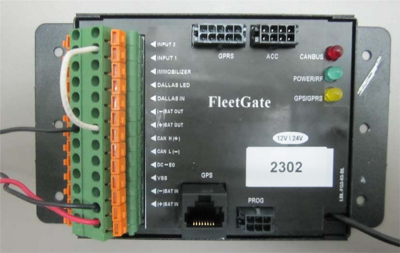
JAKFG3E
Mar 08, 2015Car Data Logger
Equipment Class
DSS - Part 15 Spread Spectrum Transmitter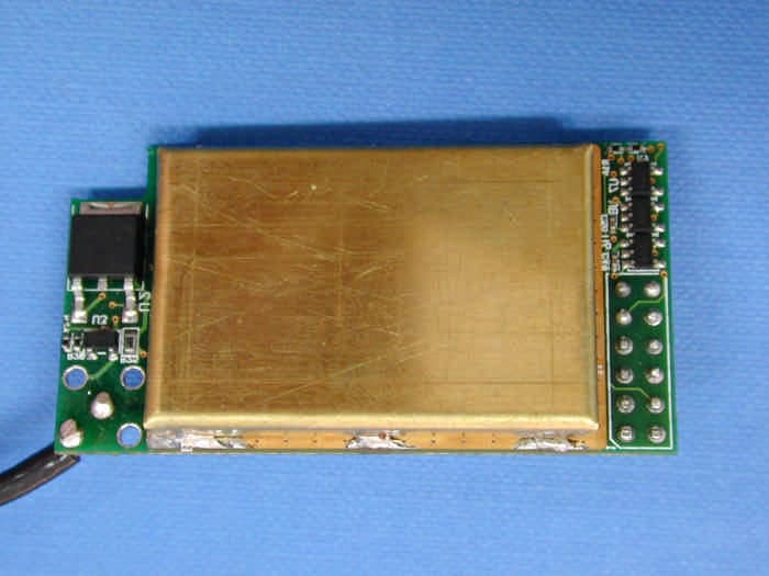
JAKRM915
Sep 28, 2003Spread Spectrum Transmitter
Equipment Class
DSS - Part 15 Spread Spectrum TransmitterJAKRCB-02
Dec 10, 1995DCD - Part 15 Low Power Transmitter Below 1705 kHz
Equipment Class
DCD - Part 15 Low Power Transmitter Below 1705 kHz