JAKRM915Spread Spectrum Transmitter
Roseman Engineering Ltd.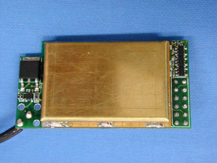
Click to zoom
Application Details
- Equipment Class
- DSS - Part 15 Spread Spectrum Transmitter
- Date of Grant
- Sep 28, 2003
- Application Purpose
- Original Equipment
- Date of Application
- Sep 28, 2003
- Equipment Note
- Spread Spectrum Transmitter
- Frequency Range
- 914.00000000 - 928.00000000
- Company
- Roseman Engineering Ltd.
- Country
- Israel
Documents & Files
Document Text
Text extracted from the exhibit documents filed with the FCC. Open a document above to read the original.
Users Manual
Draft User Manual RM915 Notes: This device complies with Part 15 of the FCC Rules. Operation is subject to the following two conditions: (1) This device may not cause harmful interference, and (2) this device must accept any interference received, including interference that may cause undesired operation. The digital portion of the transceiver has been tested and found to comply with the limits for a Class B digital device, pursuant to part 15 of the FCC Rules. These limits are designed to provide reasonable protection against harmful interference in a residential installation. This equipment generates, uses and can radiate radio frequency energy and, if not installed and used in accordance with the instructions, may cause harmful interference to radio communications. However, there is no guarantee that interference will not occur in a particular installation. If this equipment does cause harmful interference to radio or television reception, which can be determined by turning the equipment off and on, the user is encouraged to try to correct the interference by one or more of the following measures: -Reorient or relocate the receiving antenna. -Increase the separation between the equipment and receiver. Connect the equipment into an outlet on a circuit different from that to which the receiver is connected. -Consult the dealer or an experienced radio/TV technician for help. Installation When the module is attached to Roseman vehicle unit, the antenna should be installed on the top inner side of the windowpane of the vehicle. Warning! The user and the installer should be aware that changes and modifications not expressly approved by Roseman Engineering Ltd. could void the user’s authority to operate the equipment. NOTE: The antenna used for this transmitter must be installed to normally provide minimum separation distance of at least 20 cm from all persons and must not be co-located or operating in conjunction with any other antenna or transmitter
Block Diagram
ROSEMAN ENGINEERING LTD. 65 Weizman St. Givataim 53468, ISRAEL Tel: 972-3-5731801 Fax: 972-3-5731807 E-mail:[email protected] RM 915 Transceiver module Block Diagram +V Level Converters 5 MHz Transceiver 16 MHz CPU Power Supply 3V GND Data Out Data In TX Flag Standby Master / Slave 5V
Cover Letter(s)
ROSEMAN ENGINEERING LTD. 65 Weizman St. Givataim 53468, ISRAEL Tel: 972-3-5731801 Fax: 972-3-5731807 E-mail:[email protected] Letter requesting confidentiality 20 September, 2003 American TCB 6731 Whittier Ave Suite C110 McLean, VA 22101 USA Subject: Request for confidentiality for 915 MHz Transceiver module, FCC ID:JAKRM915 Dear Gentlemen, We apply to you with request to withhold Roseman Engineering Ltd trade secrets in Application for modular ap[proval for FCC ID: JAKRM915. These trade secrets can be found in the transmitter schematic diagram (1 page of this application). Many thanks in advance. Sincerely, Lior Yehoshua Chief Engineer
Cover Letter(s)
ROSEMAN ENGINEERING LTD. 65 Weizman St. Givataim 53468, ISRAEL Tel: 972-3-5731801 Fax: 972-3-5731807 E-mail:[email protected] September 20, 2003 American TCB 6731 Whittier Ave Suite C110 McLean, VA 22101 USA Subject: Application for modular approval of 915 MHz Transceiver module, model RM915, FCC ID: JAKRM915 Dear Gentlemen, Please find attached our application for modular approval of 915 MHz Transceiver module, model RM915, FCC ID: JAKRM915, prepared in accordance with FCC Rules, parts 15 and 2. The product testing and this application for modular approval were performed by Hermon Laboratories, which is listed by FCC. Hermon Labs responsible person is Mr. Gonen Usishkin, tel: 011 972 4628 8001, fax:011 972 4628 8277, e-mail: [email protected] . Please send an invoice to Hermon Labs. We hope this application satisfies your requirements. Sincerely, Lior Yehoshua Cheaf Engineer
Cover Letter(s)
ROSEMAN ENGINEERING LTD. 65 Weizman St. Givataim 53468, ISRAEL Tel: 972-3-5731801 Fax: 972-3-5731807 E-mail:[email protected] September 20, 2003 American TCB 6731 Whittier Ave Suite C110 McLean, VA 22101 USA Subject: Application for modular approval of 915 MHz Transceiver module, model RM915, FCC ID: JAKRM915 Dear Gentlemen, Please find attached our application for modular approval of 915 MHz Transceiver module, model RM915, FCC ID: JAKRM915, prepared in accordance with FCC Rules, parts 15 and 2. 1. The module has its own RF shielding. 2. The module has buffered modulation/data input. 3. The module has its own power supply regulation. 4. The module complies with antenna requirements of section 15.203 and 15.204(c). 5. The module was tested in stand-alone configuration. 6. The module is labeled with its own FCC ID number. 7. The module is provided with adequate instructions explaining specific operation requirements applicable to the module. The numbered requirements identified above are addressed in the application for the module authorization. The product testing and this application for modular approval were performed by Hermon Laboratories, which is listed by FCC. Hermon Labs responsible person is Mr. Gonen Usishkin, tel: 011 972 4628 8001, fax:011 972 4628 8277, e-mail: [email protected] . Please send an invoice to Hermon Labs. We hope this application satisfies your requirements. Sincerely, Lior Yehoshua Chief Engineer
External Photos
Transceiver module, general view Transceiver module, view with antenna
ID Label/Location Info
Label placement description The size of the module is 28*53 mm. We will attach it to the center of the cover shield. The label for the module is: The label for the equipment containing this module will be:
Internal Photos
Transceiver module without shield, first side Transceiver module, second side
Operational Description
ROSEMAN ENGINEERING LTD. 65 Weizman St. Givataim 53468, ISRAEL Tel: 972-3-5731801 Fax: 972-3-5731807 E-mail:[email protected] Transceiver module description General description A low power FHSS transceiver module operates at the ISM frequency band 902-928 MHz. The module can operate in two different modes, master or slave. The mode is defined by external input. This feature allows the user to build a point-to-multipoint wireless network based on this module. The module has 12 pins for assembling to other devices. The description of the pins is added in table 2.3.1. Data is transferred into or out of the module by serial communication with baud rate of 28800. The module has an integral antenna without RF connector. We intend to use the module as a slave in a vehicle device and as a master in a station controller. The environment is a fuel station. Technical description The device is a complete RF transmitter, it has its own reference oscillator and permanently attached antenna. The only connectors are power supply and data inputs. The device has its own RF shielding. The data inputs are buffered. The device operates with DC voltage of 9 to 30 V DC. Current consumption is maximum 50 mA. The module includes power supply regulator that supplies 3 V DC to the circuit. The STANDBY input of the module defines if it is enabled. When it is zero the module does not operate. When it is positive the module is in full operation. The MASTER\SLAVE input defines its operation mode. When it is zero, it operates as master, when it is positive it operates as slave. When the module operates as master it transmits a frame with different frequency every 380 ms. The frequency is changed on a predetermined, pseudo random pattern according to the table 2. There are 51 different frequencies in the list. The occupancy time on any frequency is 101.4 ms. The cycle period is 51*380ms which is 19.38 s. The transmission frame is divided into 19 time slots, 20 ms each. The second and the last slots are not used. The first time slot is used for one beacon transmission of 5.8 ms and a command of up to 7 ms. The other active time slots contain only the beacon and leave the slot open for the response. This means that the maximum Tx ON time is 17*5.8 + 7 = 105.6 ms. The user may send data to the module only during the last time slot. The module signals this time slot by outputting low level at the TXFLAG output. When the module operates as a slave it is most of time receiver. It transmits only when the user sends data. When the receiver is not synchronized on the master hopping frequencies, it hops every 90 ms from channel to channel according to the frequency list, until is receives the beacon from the master. Than it hops every 380 ms synchronized with the master. In slave mode the TXFLAG is not used. The user may send the data to the module at any time. The user can define at which time slot the data will be transmitted to the air. The data is transferred to or from the module by serial communication with baud rate of 28800. The module includes a CPU. The CPU is a buffer for the data inputs. It receives the data from the user at any time and sends it at the correct time slot to the transceiver. The module includes its own RF shield and cable dipole antenna without connector. The output power is constant and equals to 18 dBm. The inputs\outputs are buffered through 3 V – 5 V converters. These converters need the 5 V DC for conversion of the signal levels. ROSEMAN ENGINEERING LTD. 65 Weizman St. Givataim 53468, ISRAEL Tel: 972-3-5731801 Fax: 972-3-5731807 E-mail:[email protected] Table 1 Transceiver module ports and lines Connector Port NAME Input/Output Port detailed description J1.1 GND INPUT GROUND J1.2 +V INPUT 9-30 VDC J1.3 D-OUT OUTPUT SERIAL DATA OUT, BAUD RATE: 28800 J1.4 D-IN INPUT SERIAL DATA IN, BAUD RATE: 28800 J1.5 TXFLAG OUTPUT IN SLAVE MODE: NOT USED IN MASTER MODE: WHEN 0, USER IS ALLOWED TO SEND DATA J1.6 +5V INPUT +5V FOR LEVEL ADAPTAIONS J1.7 STANDBY INPUT 0 – NO OPERATION, 1 – FULL OPERATION J1.8 MASTER\SLAVE INPUT 0 – MASTER, 1 – SLAVE * J1.9,J1.10,J1.11,J1.12 – NOT CONNECTED ROSEMAN ENGINEERING LTD. 65 Weizman St. Givataim 53468, ISRAEL Tel: 972-3-5731801 Fax: 972-3-5731807 E-mail:[email protected] Transmitter description Type of equipment X Stand-alone (Equipment with or without its own control provisions) Combined equipment (Equipment where the radio part is fully integrated within another type of equipment) Plug-in card (Equipment intended for a variety of host systems) Other: Operating frequency range 914.8 – 927.6 MHz Spread spectrum technique used X Frequency hopping (FHSS) Digitally modulated Combined Spread spectrum parameters chip sequence length (bits) Dig. Mod. spectrum width (MHz) total number of hops (units) 51 dwell time (milliseconds) 202 bandwidth per hop (MHz) 0.185 FHSS max. separation of hops (MHz) 0.26 Transmitter aggregate data rate (bits per second) 32 kbps Normal test signal PRBS Maximum rated output power At transmitter permanent external 50 Ω rf output connector (dBm) Effective radiated power (for equipment with integral antenna) (dBm) 18 X No Yes continuous variable stepped variable stepsize (dB):............ minimum RF power (dBm):............ Is transmitter output power variable? maximum RF power (dBm):............ Transmitter power source Battery Nominal rated voltage (VDC) Nickel Cadmium Lithium Other X DC Nominal rated voltage (VDC) 9 to 30 AC mains Nominal rated voltage (VAC) Is there common power source for transmitter and receiver X yes no Antenna technical characteristics Type Manufacturer Model number Gain with temporary RF connector Integral X without temporary RF connector ½ wave centre fed dipole Galtronics 021006061-2583 0 dBi External External antenna connection - NA standard connector unique coupling ROSEMAN ENGINEERING LTD. 65 Weizman St. Givataim 53468, ISRAEL Tel: 972-3-5731801 Fax: 972-3-5731807 E-mail:[email protected] Frequency Hop…
Text truncated - open the document above for the full version.
RF Exposure Info
Environmental evaluation and exposure limit according to FCC CFR 47part 1, §1.1307, §1.1310 Limit for power density for general population/uncontrolled exposure is 0.61 mW/cm 2 . P T The power density P (mW/cm 2 ) = ------------- , where 4π r 2 P T is the maximum equivalent isotropically radiated power (EIRP). In our case P T is 17.8 dBm + 0 dBi (antenna gain) = 17.8 dBm = 60.25 mW, and the power density at 20 cm (minimum safe distance, required for mobile devices), calculated as follows: 60.25 / 4 π 20 2 = 0.012 mW/cm 2 << 0.61 mW/cm 2 was found far below the limit. Hence, no safety hazard exists for human being.
Test Report
This report is in conformity with ISO/IEC 17025. The A2LA logo endorsement applies only to the test methods and the standards that are listed in the scope of Hermon Laboratories accreditation. The test results relate only to the items tested. This test report must not be reproduced in any form except in full with the approval of Hermon Laboratories Ltd. Page 1 of 109 Document ID: ROSRAD_FCC.15655 Date of Issue: September 2003 HERMON LABORATORIES Electrical Hermon Laboratories Ltd. P.O.Box 23 Binyamina 30500, Israel Tel.+972 46288001 Fax.+972 46288277 e-mail: [email protected] RADIO TEST REPORT according to 47CFR Part 15, §15.247 and subpart B for Roseman Engineering Ltd EQUIPMENT UNDER TEST: 915 MHz transceiver module Model: RM915 Page 2 of 109 Document ID: ROSRAD_FCC.15655 Date of Issue: September 2003 HERMON LABORATORIES Hermon Laboratories Ltd. P.O.Box 23 Binyamina 30500, Israel Tel.+972 46288001 Fax.+972 46288277 e-mail: [email protected] Contents 1 Project information..........................................................................................................................3 2 Summary of tests.............................................................................................................................4 3 EUT description...............................................................................................................................5 3.1 GENERAL DESCRIPTION........................................................................................................................................................5 3.2 EUT TEST CONFIGURATION..................................................................................................................................................5 3.3 TRANSMITTER DESCRIPTION.................................................................................................................................................7 4 Test results......................................................................................................................................8 4.1 OCCUPIED BANDWIDTH OF HOPPING CHANNELS AND CHANNEL CARRIER FREQUENCIES SEPARATION ACCORDING TO § 15.247(A)(1).....................................................................................................................................................................8 4.2 NUMBER OF HOPPING CHANNELS ACCORDING TO § 15.247(A)(1)........................................................................................10 4.3 AVERAGE TIME OF HOPPING FREQUENCY OCCUPANCY ACCORDING TO § 15.247(A)(1), (F)...................................................11 4.4 MAXIMUM PEAK OUTPUT POWER TEST ACCORDING TO §15.247 (B)(1), (B)(2), (B)(3)..........................................................12 4.5 OUT OF BAND RADIATED EMISSIONS TEST ACCORDING TO §15.247(C).................................................................................13 4.6 UNINTENTIONAL RADIATED EMISSIONS TEST ACCORDING TO §15.109..................................................................................14 Appendix A Plots..................................................................................................................................15 Appendix B Test setup photographs....................................................................................................89 Appendix C Example of hopping frequency..........................................................................................94 Appendix D Test equipment used for tests...........................................................................................95 Appendix E Test equipment correction factors.....................................................................................96 Appendix F General information.........................................................................................................109 TEST FACILITY DESCRIPTION.......................................................................................................................................................109 ABBREVIATIONS AND ACRONYMS.................................................................................................................................................109 SPECIFICATION REFERENCES......................................................................................................................................................109 Page 3 of 109 Document ID: ROSRAD_FCC.15655 Date of Issue: September 2003 HERMON LABORATORIES Hermon Laboratories Ltd. P.O.Box 23 Binyamina 30500, Israel Tel.+972 46288001 Fax.+972 46288277 e-mail: [email protected] 1 Project information EUT attributes Test item 915 MHz transceiver module Type (Model) RM915 Software revision of radio unit 1.00 Equipment FCC code DSS Applicant information Applicant’s responsible person Mr. Lior Yehoshua, chief engineer Applicant/Manufacturer Roseman Engineering Ltd. Address 65, Weizman street City Givataim Postal code 53468 Country Israel Telephone number +972 3 5731 801 Telefax number +972 3 5731 807 Test details Project number 15655 Location Hermon Laboratories Receipt date August 21, 2003 Test started August 21, 2003 Test completed September 1, 2003 Purpose of test Apparatus compliance verification in accordance with emission requirements Test specifications 47CFR Part 15, §15.247 and subpart B Page 4 of 109 Document ID: ROSRAD_FCC.15655 Date of Issue: September 2003 HERMON LABORATORIES Hermon Laboratories Ltd. P.O.Box 23 Binyamina 30500, Israel Tel.+972 46288001 Fax.+972 46288277 e-mail: [email protected] 2 Summary of tests The tests listed in the table below were performed. The EUT was found complying with the limits of 47CFR Part 15, §15.247 and subpart B. Parameter Subclause Tested by Date tested Verdict Remarks Transmitter characteristics Occupied bandwidth of hopping channel 15.247 (a)(1) (i – iii) Mr. I. Fershtater, test engineer August 21, 2003 Pass Hopping channels frequency separation 15.247 (…
Text truncated - open the document above for the full version.
Test Setup Photos
Photograph 1 Setup for conducted emission at AC line measurements Photograph 2 Spurious emission measurement setup in anechoic chamber, Loop antenna in vertical polarization Photograph 3 Spurious emission measurement setup in anechoic chamber, Biconilog antenna in vertical polarization Photograph 4 Spurious emission measurement setup in anechoic chamber, Double ridged guide antenna in vertical polarization Photograph 5 Spurious emission measurement setup at OATS, Double ridged guide antenna in vertical polarization
Contact Information
Applicant
Haim Kashi(Hardware Engineer)
Technical Contact
Hermon LaboratoriesGonen Usishkin
[email protected]972-4-628-8001
Harakevet Industrial zone, · Binyamina · Israel
Test Firm
Hermon Laboratories Ltd.Alexander Usoskin
Technical Specifications
| # | Rule Parts | Frequency Range | Power Output |
|---|---|---|---|
| 1 | 15C | 914 MHz - 928 MHz | 60.00 mW |
Other Applications from Roseman Engineering Ltd.
JAKNR-G5
Dec 01, 2024Nozzle Reader
Equipment Class
DCD - Part 15 Low Power Transmitter Below 1705 kHz
JAKNR-DMR
Jan 19, 2023Dual Nozzle Tag
Equipment Class
DSS - Part 15 Spread Spectrum Transmitter
JAKFG3E
Mar 08, 2015Car Data Logger
Equipment Class
DSS - Part 15 Spread Spectrum Transmitter
JAKFG3
Dec 03, 2013CAR DATA LOGGER-MODULAR FLEET GATE
Equipment Class
DSS - Part 15 Spread Spectrum TransmitterJAKRCB-02
Dec 10, 1995DCD - Part 15 Low Power Transmitter Below 1705 kHz
Equipment Class
DCD - Part 15 Low Power Transmitter Below 1705 kHz