JFE-D2D000032.4 GHz WIRELESS LAN ROUTER
ParkerVision Inc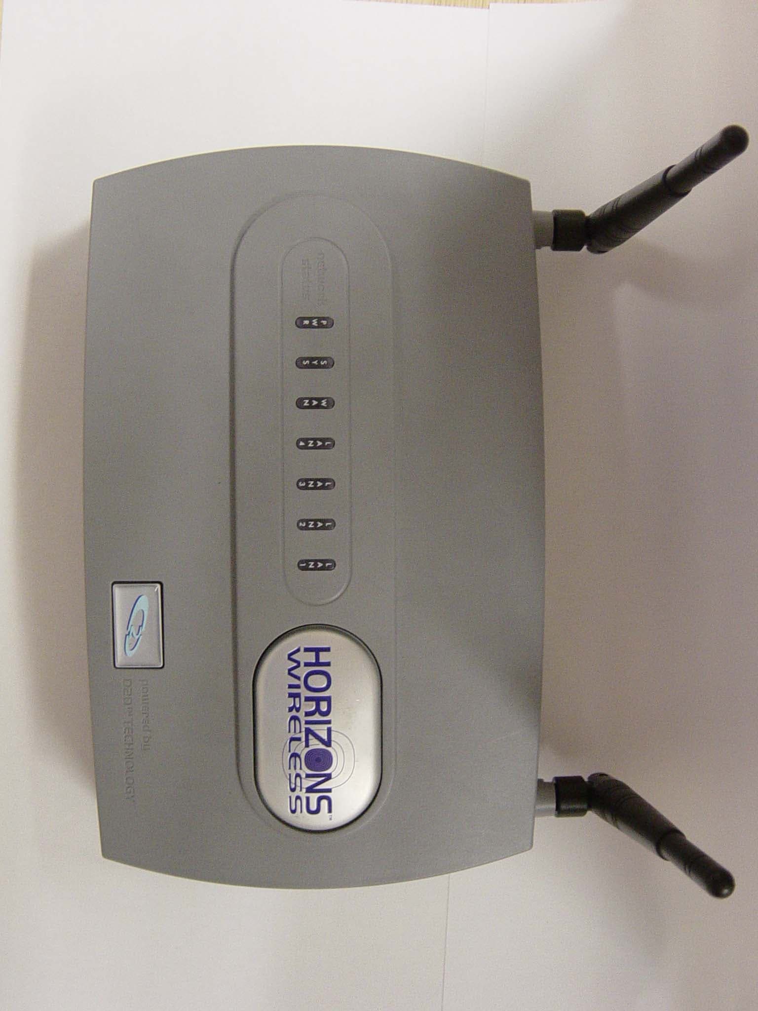
Click to zoom
Application Details
- Equipment Class
- DSS - Part 15 Spread Spectrum Transmitter
- Date of Grant
- Mar 10, 2004
- Application Purpose
- Original Equipment
- Date of Application
- Mar 10, 2004
- Equipment Note
- 2.4 GHz WIRELESS LAN ROUTER
- Frequency Range
- 2412.00000000 - 2462.00000000
- Company
- ParkerVision Inc
- Country
- United States
Documents & Files
Document Text
Text extracted from the exhibit documents filed with the FCC. Open a document above to read the original.
Users Manual
Horizons Model 1500WR Wireless 4-Port Router User’s Guide www.direct2data.com REVISION: 1 VERSION: 030104A DATE: March 2004 PRELIMINARY Horizons 1500WR Wireless 4-Port Router 2 ParkerVision COPYRIGHT ©2003 ParkerVision Inc. All rights reserved. ParkerVision Horizons™ and D2D™ Technology are registered trademarks of ParkerVision Inc. All specifications are subject to change without notice. May include one or more of the following patents: US6421534, US6049706, US6266518, US6061555, US6061551,US6353735, US6091940, US6370371 Additional Patents Pending. Designed and manufactured in the USA. FCC INTERFERENCE STATEMENT FCC ID: JFE-D2D00003 This device complies with Part 15 of the FCC rules. Operation is subject to the following two conditions: This device may not cause harmful interference. This device must accept any interference received, including interference that may cause undesired operations. This equipment has been tested and found to comply with the limits for a Class B digital device pursuant to Part 15 of the FCC Rules. These limits are designed to provide reasonable protection against harm- ful interference in a commercial environment. This equipment generates, uses, and can radiate radio frequency energy, and if not used in accordance with the instructions, may cause harmful interference to radio communications. If this equipment does cause harmful interference to radio/television reception, which can be determined by turning the equipment off and on, the user is encouraged to try to correct the interference by one of more of the following measures: Reorient or relocate the receiving antenna. Increase the separation between the equipment and the receiver. Connect the equipment to an outlet on a circuit different from that to which the receiver is connected. Consult the dealer or an experienced radio/TV technician for help. INFORMATION TO USER: THE USER’S MANUAL OR INSTRUCTION MANUAL FOR AN INTENTION- AL OR UNINTENTIONAL RADIATOR SHALL CAUTION THE USER THAT CHANGES OR MODIFICA- TIONS NOT EXPRESSLY APPROVED BY THE PARTY RESPONSIBLE FOR COMPLIANCE COULD VOID THE USER’S AUTHORITY TO OPERATE THE EQUIPMENT. “FCC RF exposure requirements: When in operation, the device should be located such that it is more than 20 cm. away from people and their person. This transmitter is restricted for use with the specific antenna(s) tested in the application for Certification. The antenna(s) used for this transmitter must not be co-located or operating in conjunction with any other antenna or transmitter.” Horizons 1500WR Wireless 4-Port Router 3 ParkerVision LIMITED WARRANTY PLEASE READ THIS MANUFACTURER’S GUARANTEE CAREFULLY TO UNDERSTAND YOUR RIGHTS AND OBLIGATIONS. MANUFACTURER’S GUARANTEE AND LIMITATION OF LIABILITY Note: The following guarantee is not restricted to any territory and does not affect any statutory rights that you may have. The term “Hardware Device” means the enclosed Direct2Data™ Technologies Hardware Device. This Manufacturer’s Guarantee does not cover your data, or any separate software, whether or not packaged or included with the Hardware Device. Direct2Data Technologies GUARANTEE. Direct2Data Technologies guarantees (this “Guarantee”) that on the day you receive the Hardware Device and for the next (1) year thereafter (a) the Hardware Device will be substantially free from defects in materials and workmanship, and (b) any support services provided by Direct2Data Technologies will be substantially as described in applicable written materials provided to you by Direct2Data Technologies, and Direct2Data Technologies support engineers will use reasonable efforts, care and skill to solve any problem issues. In the event that the Hardware Device fails to comply with this Guarantee, Direct2Data Technologies shall either, at Direct2Data Technologies’ option, (a) repair or replace the Hardware Device or (b) return the price you paid for the Hardware Device (if any), provided that you return the Hardware Device to Direct2Data Technologies with a copy of your receipt of purchase. You may exercise this remedy without charge, except that you are responsible for any expenses you may incur. This Guarantee is void if failure of the Hardware Device results from any accident, abuse or misapplication. Any replacement Hardware Device shall be guaranteed for the remainder of the original Guarantee period or thirty (30) days, whichever is longer. Direct2Data Technologies shall not be liable for any loss or damage that you could have reasonably avoided, for example, by backing up your software and files regularly, In addition, you may receive a full refund of your purchase price within the first 30 days following the purchase of the Hardware Device for any reason provided that you return the Hardware Device to the Manufacturer in its original condition, accompanied by the receipt of purchase. EXCLUSION OF ALL OTHER TERMS. YOU AGREE THAT THIS GUARANTEE IS YOUR SOLE GUARANTEE IN RELATION TO THE HARDWARE DEVICE AND ANY SUPPORT SERVICES. DIRECT2DATA TECHNOLOGIES AND ITS SUPPLIERS MAKE NO OTHER GUARANTEES OR WARRANTIES WITH RESPECT TO THE HARDWARE DEVICE, THE SUPPORT SERVICES AND ANY PRODUCT MANUAL(S) OR OTHER WRITTEN MATERIALS THAT ACCOMPANY THE HARDWARE DEVICE. TO THE MAXIMUM EXTENT PERMITTED BY APPLICABLE LAW AND SUBJECT TO THIS GUARANTEE, DIRECT2DATA TECHNOLOGIES AND ITS SUPPLIERS DISCLAIM ALL WARRANTIES, CONDITIONS AND OTHER TERMS, EITHER EXPRESS OR IMPLIED (WHETHER BY STATUTE, COMMON LAW, COLLATERALLY OR OTHERWISE), INCLUDING BUT NOT LIMITED TO ANY (IF ANY) IMPLIED WARRANTIES OR CONDITIONS OF MERCHANTABILITY, SATISFACTORY QUALITY AND FITNESS FOR PARTICULAR PURPOSE, LACK OF VIRUSES, LACK OF NEGLIGENCE, LACK OF WORKMANLIKE EFFORT, TITLE, AUTHORITY, OR NONINFRINGEMENT WITH RESPECT TO THE HARDWARE DEVICE, THE SUPPORT SERVICES AND THE PRODUCT MANUAL(S) OR OTHER WRITTEN MATERIALS THAT ACCOMPANY THE HARDWARE DEVICE. Continued Next Page Horizons 1500WR Wireless 4-Port Router 4 ParkerVision ANY IMPLIED WA…
Text truncated - open the document above for the full version.
Users Manual
Horizons 1500WR Wireless 4-Port Router 107 ParkerVision 13.8 Configuring Security To change your 1500WR Wireless Router’s security settings, click ADVANCED, REMOTE MANAGE- MENT and then the Security tab. The screen appears as shown. If an outside user attempts to probe an unsupported port on your 1500WR Wireless Router, an ICMP response packet is automatically returned. This allows the outside user to know the 1500WR Wireless Router exists. The 1500WR Wireless Router series support anti-probing, which prevents the ICMP response packet from being sent. This keeps outsiders from discovering your 1500WR Wireless Router when unsupported ports are probed. The following table describes the labels in this screen. Security LABELDESCRIPTION ICMPInternet Control Message Protocol is a message control and error-reporting protocol between a host server and a gateway to the Internet. ICMP uses Internet Protocol (IP) datagrams, but the messages are processed by the TCP/IP software and directly apparent to the application user. Respond to Ping on The 1500WR Wireless Router will not respond to any incoming Ping requests when Disable is selected. Select LAN to reply to incoming LAN Ping requests. Select WAN to reply to incoming WAN Ping requests. Otherwise select LAN&WAN to reply to both incoming LAN and WAN Ping requests. Do not respond to requests for unauthorized services Select this option to prevent hackers from finding the 1500WR Wireless Router by probing for unused ports. If you select this option, the 1500WR Wireless Router will not send ICMP response packets to port request(s) for unused ports, thus leaving the unused ports and the 1500WR Wireless Router unseen. If the firewall blocks a packet from the WAN, the 1500WR Wireless Router sends a TCP reset packet. Use the “sys firewall tcprst rst off’ command in the command interpreter if you want to stop the 1500WR Wireless Router from sending TCP reset packets. ApplyClick Apply to save your changes back to the 1500WR Wireless Router. ResetClick Reset to begin configuring this screen afresh. Horizons 1500WR Wireless 4-Port Router 108 ParkerVision Horizons 1500WR Wireless 4-Port Router 109 ParkerVision This part provides information and configuration instructions for UPnP (Universal Plug and Play) and the logs. Part VI UPnP and LOGS Horizons 1500WR Wireless 4-Port Router 110 ParkerVision Chapter 14 UPnP Screen This chapter introduces the Universal Plug and Play feature of the 1500WR 14.1 Universal Plug and Play Overview Universal Plug and Play (UPnP) is a distributed, open networking standard that uses TCP/IP for simple peer-to-peer network connectivity between devices. A UPnP device can dynamically join a network, obtain an IP address, convey its capabilities and learn about other devices on the network. In turn, a device can leave a network smoothly and automatically when it is no longer in use. 14.1.1 How Do I Know If I’m Using UPnP? UPnP hardware is identified as an icon in the Network Connections folder (Windows XP). Each UPnP compatible device installed on your network will appear as a separate icon. Selecting the icon of a UPnP device will allow you to access the information and properties of that device. 14.1.2 NAT Traversal UPnP NAT traversal automates the process of allowing an application to operate through NAT. UPnP network devices can automatically configure network addressing, announce their presence in the network to other UPnP devices and enable exchange of simple product and service descriptions. NAT traversal allows the following: • Dynamic port mapping • Learning public IP addresses • Assigning lease times to mappings Windows Messenger is an example of an application that supports NAT traversal and UPnP. See the SUA/NAT chapter for further information about NAT. 14.2 Cautions with UPnP The automated nature of NAT traversal applications in establishing their own services and opening firewall ports may present network security issues. Network information and configuration may also be obtained and modified by users in some network environments. All UPnP-enabled devices may communicate freely with each other without additional configuration. Disable UPnP if this is not your intention. 14.3 Configuring UPnP Click ADVANCED and then UPnP to display the screen shown on the next page. Horizons 1500WR Wireless 4-Port Router 111 ParkerVision 14.3 Configuring UPnP - Continued The following table describes the labels in this screen. Configuring UPnP LABELDESCRIPTION Enable the Universal Plug and Play (UPnP) feature Select this check box to activate UPnP. Be aware that anyone could use a UPnP application to open the web Web Configuration Utility’s login screen without entering the 1500WR Wireless Router’s IP address (although you must still enter the password to access the web Web Configuration Utility). Allow users to make configuration changes through UPnP Select this check box to allow UPnP-enabled applications to automatically configure the 1500WR Wireless Router so that they can communicate through the 1500WR Wireless Router, for example by using NAT traversal, UPnP applications automatically reserve a NAT forwarding port in order to communicate with another UPnP enabled device; this eliminates the need to manually configure port forwarding for the UPnP enabled application. Allow UPnP to pass through Firewall Select this check box to create a static LAN to LAN/1500WR Wireless Router rule that allows forwarding of ports 1900 and 80. Selecting this check box also creates a dynamic firewall rule every time a NAT forwarding port is reserved for UPnP. This setting remains active until you disable UPnP or clear this check box. Clear this check box to have the firewall block all UPnP application packets (for example, MSN packets) instead of creating a firewall rule for them. UPnP NameThis identifies the 1500WR Wireless Router in UPnP applications. ApplyClick Apply to save your changes back to the 1500WR Wireless Router. ResetClick Reset to begin c…
Text truncated - open the document above for the full version.
Test Report
TIMCO ENGINEERING INC. 849 NW State Road 45 Newberry, Florida 32669 http://www.timcoengr.com 888.472.2424 F 352.472.2030 email: [email protected] APPLICANT: PARKERVISION INC. Test Report Product Name: WIRELESS LAN FCC ID: JFE-D2D00003 Applicant: PARKERVISION INC. 8493 BAYMEADOWS WAY JACKSONVILLE, FL 32256 Date Receipt: FEBRUARY 26, 2004 Date Tested: MARCH 2, 2004 FCC ID: JFE-D2D00003 REPORT #: P\PARKERJFE\236AUT4\236AUT4TestReport.doc COVER PAGE TIMCO ENGINEERING INC. 849 NW State Road 45 Newberry, Florida 32669 http://www.timcoengr.com 888.472.2424 F 352.472.2030 email: [email protected] APPLICANT: PARKERVISION INC. TABLE OF CONTENTS TEST REPORT CONTAINING: PAGE 1.............LETTER OF EXPLANATION PAGE 2.............LIST OF TEST EQUIPMENT PAGE 3.............TEST PROCEDURES PAGE 4.............POWERLINE CONDUCTED INTERFERENCE PAGE 5-7...........POWERLINE CONDUCTED PLOTS PAGE 8.............OCCUPIED BANDWIDTH AND POWER OUTPUT PAGE 9.............6 dB BANDWIDTH PLOTS PAGE 10............SPURIOUS EMISSIONS AT ANTENNA TERMINALS DATA METHOD OF MEASURING RF CONDUCTED PAGE 11............RADIATION INTERFERENCE TEST DATA PAGE 12............METHOD OF MEASURING RADIATED SPURIOUS EMISSIONS PAGE 13-15.........RADIATED SPURIOUS EMISSIONS INTO ADJACENT RESTRICTED BANDS PAGE 16............POWER SPECTRAL DENSITY EXHIBITS INCLUDED: REQUEST FOR CONFIDENTIALITY LETTER BLOCK DIAGRAM SCHEMATICS USERS MANUAL LABEL SAMPLE LABEL LOCATION EXTERNAL PHOTOGRAPHS INTERNAL PHOTOGRAPHS OPERATIONAL DESCRIPTION TEST SET UP PHOTOGRAPHS FCC ID: JFE-D2D00003 REPORT #: P\PARKERJFE\236AUT4\236AUT4TestReport.doc TABLE OF CONTENTS TIMCO ENGINEERING INC. 849 NW State Road 45 Newberry, Florida 32669 http://www.timcoengr.com 888.472.2424 F 352.472.2030 email: [email protected] APPLICANT: PARKERVISION INC. MARCH 2, 2004 Federal Communications Commission Authorization and Evaluation Division 7435 Oakland Mills Road Columbia, MD 21046 SUBJECT: PARKERVISION INC. FCC ID: JFE-D2D00003 To Whom It May Concern: The attached application is for a direct sequence spread spectrum wireless router. This system has only one type of antenna, permanently attached dipoles with a gain of 2dBi. PARKERVISION INC. purchases standard antennas from the manufacturer. Should you have any questions or require any further information with regards to this, please feel free to contact me. Sincerely, Mario R. de Aranzeta C.E.T. MRD/sh Encl. FCC ID: JFE-D2D00003 REPORT #: P\PARKERJFE\236AUT4\236AUT4TestReport.doc Page 1 of 16 TIMCO ENGINEERING INC. 849 NW State Road 45 Newberry, Florida 32669 http://www.timcoengr.com 888.472.2424 F 352.472.2030 email: [email protected] APPLICANT: PARKERVISION INC. EMC Equipment List Device Manufacturer Model Serial Number Cal/Char Date Due Date 3-Meter OATS TEI N/A N/A Listed 1/13/03 1/13/06 Biconnical Antenna Eaton 94455-1 1057 CAL 3/18/03 3/18/05 Biconnical Antenna Eaton 94455-1 1096 CAL 10/1/01 10/1/03 Double-Ridged Horn Antenna Electro- Metrics RGA-180 2319 CAL 2/17/03 2/17/05 LISN Electro- Metrics ANS-25/2 2604 CAL 10/9/01 10/9/03 LISN Electro- Metrics EM-7820 2682 CAL 3/12/03 3/12/05 Log-Periodic Antenna Eaton 96005 1243 CAL 5/8/03 5/8/05 Log-Periodic Antenna Electro- Metrics EM-6950 632 CHAR 10/15/01 10/15/03 Log-Periodic Antenna Electro- Metrics LPA-25 1122 CAL 10/2/01 10/2/03 Log-Periodic Antenna Electro- Metrics LPA-30 409 CAL 3/4/03 3/4/05 Peak Power Meter HP 8900C 2131A00545 CAL 7/2/03 7/2/05 Power Meter HP 432A 1141A07655 CAL 4/15/03 4/15/05 Silver Tower Preamplifier HP 8449B 3008A01075 CHAR 1/28/02 1/28/04 Silver Tower Quasi-Peak Adapter HP 85650A 3303A01844 CAL 10/14/02 10/14/04 Silver Tower RF Preselector HP 85685A 2620A00294 CAL 10/14/02 10/14/04 Silver Tower Spectrum Analyzer HP 8566B Opt 462 3552A22064 3638A08608 CAL 10/14/02 10/14/04 Tan Tower Preamplifier HP 8449B-H02 3008A00372 CHAR 3/4/01 3/4/03 Tan Tower Quasi-Peak Adapter HP 85650A 3303A01690 CAL 8/31/01 8/31/03 Tan Tower RF Preselector HP 85685A 3221A01400 CAL 8/31/01 8/31/03 Tan Tower Spectrum Analyzer HP 8566B Opt 462 3138A07786 3144A20661 CAL 8/31/01 8/31/03 Harmonic Mixer HP 11970K 3003A04991 N/A N/A HORN SYSTRON DONNOR DBE-520-20 N/A N/A N/A FCC ID: JFE-D2D00003 REPORT #: P\PARKERJFE\236AUT4\236AUT4TestReport.doc Page 2 of 16 TIMCO ENGINEERING INC. 849 NW State Road 45 Newberry, Florida 32669 http://www.timcoengr.com 888.472.2424 F 352.472.2030 email: [email protected] APPLICANT: PARKERVISION INC. TEST PROCEDURE GENERAL: This report shall NOT be reproduced except in full without the written approval of TIMCO ENGINEERING, INC. POWER LINE CONDUCTED INTERFERENCE: The procedure used was ANSI STANDARD C63.4- 2000 using a 50uH LISN. Both lines were observed with the UUT transmitting. The bandwidth of the spectrum analyzer was 10kHz with an appropriate sweep speed. The ambient temperature of the UUT was 76°F with a humidity of 55%. BANDWIDTH 6.0dB: The measurements were made with the spectrum analyzer's resolution bandwidth (RBW)=1 MHz and the video bandwidth (VBW) =3 MHz and the span set as shown on plot. POWER OUTPUT: The RF power output was measured at the antenna feed point using a peak power meter. ANTENNA CONDUCTED EMISSIONS: The RBW=100 kHz, VBW=300 kHz and the span set to 10.0MHz and the spectrum was scanned from 30MHz to the 10 th Harmonic of the fundamental. Above 1 GHz the resolution bandwidth was 1 MHz and the VBW = 3 MHz and the span to 50 MHz. RADIATION INTERFERENCE: The test procedure used was ANSI STANDARD C63.4-2000 using a HEWLETT PACKARD spectrum analyzer with a pre-selector. The bandwidth (RBW) of the spectrum analyzer was 100 kHz up to 1 GHz and 1 MHz above 1GHz with an appropriate sweep speed. The VBW above 1.0GHz was = 3.0MHz. The analyzer was calibrated in dB above a microvolt at the output of the antenna. The ambient temperature of the UUT was 53°F with a humidity of 17%. FCC ID: JFE-D2D00003 REPORT #: P\PARKERJFE\236AUT4\236AUT4TestReport.doc Page 3 of 16 TIMCO ENGINEERING INC. 849 NW State Road 45 Newberry, Florida 32669 http://www.t…
Text truncated - open the document above for the full version.
Contact Information
Applicant
David F Sorrells(President)
[email protected]904 737-1367
Test Firm
Timco Engineering, Inc.S Sanders
Technical Specifications
| # | Rule Parts | Frequency Range | Power Output |
|---|---|---|---|
| 1 | 15C | 2.41 GHz - 2.46 GHz | 250.00 mW |
Other Applications from ParkerVision Inc
JFE-D2D00005
Jan 20, 2005MINI PCI
Equipment Class
DTS - Digital Transmission System
JFE-D2D00004
Jul 13, 2004PCMCIA NIC WIRELESS LAN ADAPTER
Equipment Class
DTS - Digital Transmission System
JFEMDS-2003
Mar 16, 2004CAMERA CONTROL RECEIVER
Equipment Class
CXX - Communications Rcvr for use w/ licensed Tx and CBs
JFE-D2D00002
Nov 20, 2003Wireless Lan
Equipment Class
DTS - Digital Transmission System
JFE-D2D00001
Sep 28, 2003WIRELESS LAN CARD
Equipment Class
DTS - Digital Transmission System