JIC-CF001HyperX Cloud Flight Wireless Headset
Kingston Technology Company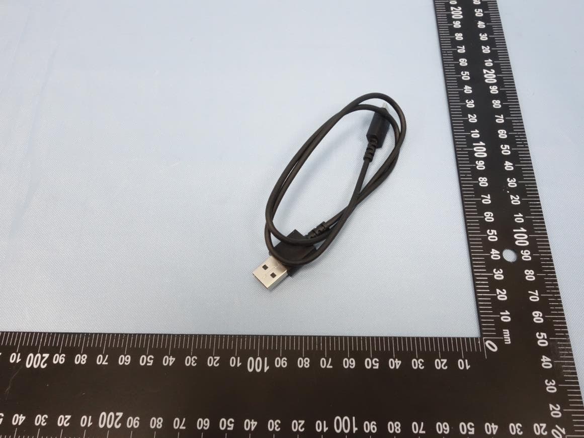
Click to zoom
Application Details
- Equipment Class
- DTS - Digital Transmission System
- Date of Grant
- Mar 22, 2020
- Application Purpose
- Original Equipment
- Date of Application
- Mar 22, 2020
- Equipment Note
- HyperX Cloud Flight Wireless Headset
- Frequency Range
- 2405.35000000 - 2477.35000000
- Company
- Kingston Technology Company
- Country
- United States
Documents & Files
Document Text
Text extracted from the exhibit documents filed with the FCC. Open a document above to read the original.
Users Manual
FRANÇAIS Présentation A - Molette de réglage du volume B - Port microphone C - Port de chargement USB D - Port de casque analogique E - Bouton Marche/ Arrêt F - Bouton de désactivation du micro G - Microphone amovible H - Adaptateur sans l I - Voyant Statut sans l J - Câble de chargement USB K - Câble de casque 3,5mm Utilisation Chargement de la batterie Il est recommandé de charger complètement votre casque-micro avant sa première utilisation. Lorsque le câble de chargement est connecté, le voyant LED de l’écouteur indique le statut. Bouton Marche/ Arrêt Marche - maintenez le bouton Marche/Arrêt pendant 3 secondes jusqu’à ce qu’un bip retentisse. Arrêt - maintenez le bouton Marche/Arrêt pendant 3 secondes jusqu’à ce qu’un bip retentisse. E et LED - Appuyez sur le bouton Marche/ Arrêt pour changer l’e et LED. Utilisation avec un PC, une PS4 TM ou un Mac® 1. Branchez l’adaptateur sans l sur le port USB d’un PC/ PS4 ou Mac. (Le voyant Statut sans l de l’adaptateur va clignoter) 2. Allumez le casque-micro. 3. Lorsque le voyant Statut sans l de l’adaptateur est allumé ( xe), le casque-micro est connecté. Remarque: Si vous utilisez votre casque-micro pour la première fois, il peut être nécessaire de le con gurer comme Périphérique d’entrée/ sortie par défaut. Utilisation comme casque analogique 1. Connectez le câble 3,5mm au port Casque du casque-micro. 2. Branchez le câble 3,5mm du casque à votre système. Remarque: Le microphone ne fonctionne pas dans cette con guration. Questions ou problèmes de con guration? Contactez l’équipe d’assistance HyperX ou consultez le manuel d’utilisation: hyperxgaming.com/support/headsets ITALIANO Panoramica A - Regolazione volume B - Ingresso microfono C - Porta USB con funzione di ricarica D - Ingresso analogico per cu at E - Pulsante di accensione F - Pulsante di esclusione microfono G - Microfono scollegabile H - Adattatore wireless I - Spia dello stato wirelesst J - Cavo di ricarica USB K - Cavo cu e con jack da 3,5 mm Istruzioni d’uso Ricarica In occasione del primo utilizzo, si consiglia di e ettuare un ciclo completo di ricarica. Una volta connesso il cavo di ricarica, il LED presente sul padiglione indicherà che le cu e sono in stato di caricamento. Pulsante di accensione Accensione - Tenere premuto il pulsante di accensione per 3 secondi no ad avvertire un beep. Spegnimento - Tenere premuto il pulsante di accensione per 3 secondi no ad avvertire un beep. E etti LED - Premere il pulsante di accensione per passare al successivo e etto LED. Uso con PC, PS4 TM o Mac® 1. Collegare l’adattatore wireless a una porta USB presente su pc, PS4 o Mac. (il LED di stato dell’adattatore wireless inizierà a lampeggiare) 2. Accendere le cu e 3. La connessione con le cu e sarà stabilità una volta che il LED di stato dell’adattatore wireless resterà acceso senza lampeggiare Nota: la prima volta che si utilizzano le cu e potrebbe essere necessario impostarle come dispositivo di ingresso e uscita audio prede nito. Uso di una cu a analogica 1. Collegare il cavo delle cu e con il jack da 3,5mm all’apposito ingresso della cu a. 2. Inserire il jack da 3,5mm dell’altra estremità del cavo delle cu e nel dispositivo. Nota: in questa con gurazione il microfono non funziona. Domande o dubbi sulla con gurazione? Contattare il team di supporto HyperX oppure consultare il manuale utente: hyperxgaming.com/support/headsets DEUTSCH Übersicht A - Lautstärkeregler B - Mikrofonbuchse C - USB-Ladeanschluss D - Analaoger Kopfhöreranschluss E - Ein/Ausschalter F - Mikrofon-Stummschalten G - Abnehmbares Mikrofon H - Drahtloser Adapter I - Drahtlose Statusanzeige J - USB-Ladekabel K - 3,5 mm Kopfhörerkabel Nutzung Laden Es wird empfohlen, dein Headset vollständig zu laden, bevor Du es zum ersten Mal verwendest. Wenn das Ladekabel angeschlossen ist, zeigt die LED das in der Ohrmuscheln an. An-/Ausschalter Spannung ein - Halte den Ein/Ausschaltknopf 3 Sekunden gedrückt, bis du ein Piepen hörst. Spannung aus - Halte den Ein/Ausschaltknopf 3 Sekunden gedrückt, bis du ein Piepen hörst. Spannung aus - Betätigen Sie den An-/Ausschalter, um durch die verschiedenen LED-E ekte zu schalten. Nutzung mit einem PC, einer PS4 TM oder einem Mac® 1. Verbinde den drahtlosen Adapter mit einem USB-Port an deinem PC, PS4 oder deinem Mac. (Das Statuslicht deines drahtlosen Adapters blinkt auf.) 2. Das Headset einschalten 3. Wenn das Statuslicht am drahtlosen Adapter nicht mehr blinkt, ist das Headset verbunden. Hinweis: Wenn Du das Headset zum ersten Mal verwendest, musst Du es möglicherweise erst als Standard-Eingabe- und Ausgabegerät festlegen. Verwendung von analogen Kopfhörern 1. Verbinde das 3,5 mm Kopfhörerkabel mit der Kopfhörerbuchse am Kopfhörer. 2. Stecke das 3,5 mm Kopfhörerkabel in das Gerät. Hinweis: Das Mikrofon funktioniert mit dieser Kon guration nicht. Hast du Fragen oder Probleme bei der Installation? Wenden Sie sich an das HyperX-Support-Team oder beziehen Sie sich auf die Bedienungsanleitung unter: hyperxgaming.com/support/headsets POLSKI Prezentacja A - Pokrętło głośności B - Port mikrofonu C - Port USB ładowania D - Analogowy port słuchawek E - Przycisk zasilania F - Przycisk wyciszenia mikrofonu G - Odłączany mikrofon H - Moduł łączności bezprzewodowej I - Wskaźnik stanu łączności bezprzewodowej J - Przewód USB do ładowania K - Przewód słuchawek 3,5 mm Użytkowanie Ładowanie Przed rozpoczęciem użytkowania zestawu słuchawkowego zalecamy jego pełne naładowanie. Po podłączeniu przewodu do ładowania wskaźnik LED na nauszniku pozwala określić stan baterii. Przycisk zasilania Włączanie zestawu - naciśnij i przytrzymaj przycisk zasilania przez 3 sekund do chwili wyemitowania sygnału dźwiękowego. Wyłączanie zestawu - naciśnij i przytrzymaj przycisk zasilania przez 3 sekundy do chwili wyemitowania sygnału dźwiękowego. Efekt świetlny - do przełączania sposobu świecenia wskaźnika LED służy przełącznik zasilania. Użytkowanie zestawu z komputerem PC lub Mac® oraz konsolą PS4 TM 1. Podłącz moduł łączn…
Text truncated - open the document above for the full version.
Attestation Statements
0 Antenna Specification for Flight cost down_Phase II Prepared by : Merry TeamDate : 2020.01.13 1 Summary • Headset Antenna 1. Antenna type: Printed Monopole2. Antenna gain: ANT1 1.8dBi / ANT2 1.7dBi • Dongle Antenna 1. Antenna type: Printed Monopole2. Antenna gain: ANT1 0dBi / ANT2 0.2dBi 2 Headset Antenna Dimensions BB Antennas DetailedDimensions 16.3 Unit: mm ANT1 10 ANT2 10 3 Radiation Pattern-Headset (1/2) Y Z X • ANT 1 Scale Freq X-Y Y-Z X-Z 2.44 GHz ANTside 4 Radiation Pattern-Headset (2/2) Y Z X • ANT 2 Scale Freq X-Y Y-Z X-Z 2.44 GHz ANTside 5 Dongle Antenna Dimensions BB 12.45 15.45 4.2 Unit: mm Antennas ANT1 ANT2 4.2 DetailedDimensions 6 Radiation Pattern-Dongle (1/2) Z Y X Printed L Printed R side • ANT1 (Printed L) Scale Freq X-Y Y-Z X-Z 2.44 GHz Printed L side Printed R 7 Radiation Pattern-Dongle (2/2) Z Y X Scale Freq X-Y Y-Z X-Z 2.44 GHz Printed L Printed R Printed R sidePrinted L side • ANT2 (Printed R)
Cover Letter(s)
QF094234 Page 1 of 1 Revision 0 Authority to Act as Agent Date: 2020-03-04 TUV Rheinland Group 762 Park Avenue Youngsville, NC 27596 To Whom It May Concern: I appoint TÜV Rheinland Taiwan Ltd. to act as our agent in the preparation of this application for equipment certification. I certify that submitted documents properly describe the device or system for which equipment certification is sought. I also certify that each unit manufactured, imported or marketed, as defined in the FCC or Industry Canada’s regulations will have affixed to it a label identical to that submitted for approval with this application. For instances where our authorized agent signs the application for certification on our behalf, I acknowledge that all responsibility for complying with the terms and conditions for Certification, as specified by TUV Rheinland Group, still resides with Kingston Technology Company / 17600 Newhope Street, Bldg. C, Fountain Valley, CA 92708, USA For TCB applications, We certify that we are not subject to denial of federal benefits, that includes FCC benefits, pursuant to Section 5301 of the Anti-Drug Abuse Act of 1988, 21 U.S.C. 862. Further, no party, as defined in 47 CFR 1.2002 (b), to the application is subject to denial of federal benefits, that includes FCC benefits. Thank you, By : George Shiu (Signature) (Print Name) Title : Project Engineer Telephone : 714-438-1877 On behalf of : Kingston Technology Company (Company Name)
Cover Letter(s)
Confidentiality Request Letter Confidentiality Request regarding application for certification of FCC ID: JIC-CF001 and IC: 3880A-CF001 Pursuant to Sections 0.457 and 0.459 of the Commission’s Rules, and IC RSP-100, Section 10, we hereby request confidential treatment of information accompanying this application as outlined below: Exhibit Type (Long Term) Exhibit Type (Short Term) Block Diagram, Schematics, Operational Description Photos External Photos Internal Test setup photos User Manual Time of confidentiality 180 days The above materials contain trade secrets and proprietary information not customarily released to the public. The public disclosure of these materials may be harmful to the applicant and provide unjustified benefits to its competitors. The applicant understands that pursuant to Section 0.457 of the Rules, disclosure of this application and accompanying documentation will not be made before the date of the Grant for this application. Pursuant to DA04-1705 June 15, 2004 of the Commission’s public notice we also request temporary confidential treatment of information accompanying this application as outlined above. Sincerely, ___________________________ Kingston Technology Company 17600 Newhope Street, Bldg. C, Fountain Valley, CA 92708, USA
External Photos
Photo Documentation Page 1 of 7 Product: HyperX Cloud Flight Wireless Headset Type Identification: CF001 Photo Documentation Page 2 of 7 Product: HyperX Cloud Flight Wireless Headset Type Identification: CF001 Photo Documentation Page 3 of 7 Product: HyperX Cloud Flight Wireless Headset Type Identification: CF001 Photo Documentation Page 4 of 7 Product: HyperX Cloud Flight Wireless Headset Type Identification: CF001 Photo Documentation Page 5 of 7 Product: HyperX Cloud Flight Wireless Headset Type Identification: CF001 Photo Documentation Page 6 of 7 Product: HyperX Cloud Flight Wireless Headset Type Identification: CF001 Photo Documentation Page 7 of 7 Product: HyperX Cloud Flight Wireless Headset Type Identification: CF001
ID Label/Location Info
FCC ID: JIC-CF001WA IC: 3880A-CF001WA FCC ID: JIC-CF001 IC: 3880A-CF001
Internal Photos
Photo Documentation Page 1 of 5 Product: HyperX Cloud Flight Wireless Headset Type Identification: CF001 Photo Documentation Page 2 of 5 Product: HyperX Cloud Flight Wireless Headset Type Identification: CF001 Antenna Photo Documentation Page 3 of 5 Product: HyperX Cloud Flight Wireless Headset Type Identification: CF001
RF Exposure Info
Produkte Products Prüfbericht - Nr.: Test Report No. 50342229 001 Seite 29 von 30 Page 29 of 30 6. Safety Human exposure 6.1 Radio Frequency Exposure Compliance 6.1.1 Electromagnetic Fields RESULT: Passed Test standard : FCC KDB Publication 447498 D01 ISED RSS-102 issue 5, Table 1 FCC: Since maximum average output power of the transmitter is 2.9174 mW < 10mW, hence the EUT is excluded from SAR evaluation according to FCC KDB publication 447498: Mobile Portable RF Exposure Canada: Maximum conducted average power: 3.05 mW --------------------------------------------- Antenna Gain: 1.8 dbi -> x 1.5 Maximum EIRP available: 4.58 mW ========================== Maximum Power available: 4.58 mW (higher of EIRP or conducted) Since maximum output power of the transmitter is 4.58mW <7mW at 10mm, hence the EUT is excluded from SAR evaluation according to Table 1 in RSS-102 When in normal use, at least 10mm between the radiated construction(antenna) and users, which indicated in internal photos (Antenna location Diagram) .
Test Report
Produkte Products TUV Rheinland Taiwan Ltd. 11F., No. 758, Sec. 4, Bade Rd., Taipei 105, Taiwan, R.O.C. Prüfbericht-Nr.: Test Report No.: 50342229 001 Auftrags-Nr.: Order No.: 238114482 Seite 1 von 30 Page 1 of 30 Kunden-Referenz-Nr.: Client Reference No.: N/A Auftragsdatum: Order date: 10-Feb-2020 Auftraggeber: Client: Kingston Technology Company, Inc., 17600 Newhope St, Fountain Valley, CA 92708, USA Prüfgegenstand: Test item: HyperX Cloud Flight Wireless Headset Bezeichnung / Typ-Nr.: Identification / Type No.: CF001 Auftrags-Inhalt: Order content: FCC Part 15C/ ISED RSS-247 Test report Prüfgrundlage: Test specification: FCC 47CFR Part 15: Subpart C Section 15.247(DTS) ISED RSS-247 ISSUE 2 FEB 2017 Wareneingangsdatum: Date of receipt: 2-Jan-2020 Prüfmuster-Nr.: Test sample No.: A001011214-002 A001011214-003 Prüfzeitraum: Testing period: 23-Jan-2020-15-Feb-2020 Ort der Prüfung: Place of testing: EMC/RF Laboratory Taipei Prüflaboratorium: Testing laboratory: TUV Rheinland Taiwan Ltd. Prüfergebnis*: Test result*: Pass geprüft von / tested by: 12-Mar-2020 Mars Y.J. Lin/ Project Engineer kontrolliert von / reviewed by: 12-Mar-2020 Ryan W. T. Chen / Project Manager Datum Date Name / Stellung Name / Position Unterschrift Signature Datum Date Name / Stellung Name / Position Unterschrift Signature Sonstiges / Other: Zustand des Prüfgegenstandes bei Anlieferung: Condition of the test item at delivery: Prüfmuster vollständig und unbeschädigt Test item complete and undamaged * Legende: 1 = sehr gut 2 = gut 3 = befriedigend 4 = ausreichend 5 = mangelhaft P(ass) = entspricht o.g. Prüfgrundlage(n) F(ail) = entspricht nicht o.g. Prüfgrundlage(n) N/A = nicht anwendbar N/T = nicht getestet Legend: 1 = very good 2 = good 3 = satisfactory 4 = sufficient 5 = poor P(ass) = passed a.m. test specification(s) F(ail) = failed a.m. test specification(s) N/A = not applicable N/T = not tested Dieser Prüfbericht bezieht sich nur auf das o.g. Prüfmuster und darf ohne Genehmigung der Prüfstelle nicht auszugsweise vervielfältigt werden. Dieser Bericht berechtigt nicht zur Verwendung eines Prüfzeichens. This test report only relates to the a. m. test sample. Without permission of the test center this test report is not permitted to be duplicated in extracts. This test report does not entitle to carry any test mark. Produkte Products Prüfbericht - Nr.: Test Report No. 50342229 001 Seite 2 von 30 Page 2 of 30 T EST S UMMARY 5.1.1 A NTENNA R EQUIREMENT RESULT: Passed 5.1.2 P EAK O UTPUT P OWER RESULT: Passed 5.1.3 6 D B B ANDWIDTH AND 99% B ANDWIDTH RESULT: Passed 5.1.4 P OWER D ENSITY RESULT: Passed 5.1.5 C ONDUCTED SPURIOUS EMISSIONS AND F REQUENCY B AND E DGE MEASURED IN 100 K H Z B ANDWIDTH RESULT: Passed 5.1.6 S PURIOUS E MISSION RESULT: Passed 5.2.1 M AINS C ONDUCTED E MISSIONS RESULT: Passed 6.1.1 E LECTROMAGNETIC F IELDS RESULT: Passed Produkte Products Prüfbericht - Nr.: Test Report No. 50342229 001 Seite 3 von 30 Page 3 of 30 Contents 1. G ENERAL R EMARKS ............................................................................................... 5 1.1 C OMPLEMENTARY M ATERIALS ................................................................................. 5 1.2 D ECISION R ULE OF CONFORMITY ................................................................................ 5 2. T EST S ITES ............................................................................................................ 6 2.1 T EST L ABORATORY ................................................................................................ 6 2.2 T EST F ACILITY ........................................................................................................ 6 2.3 L IST OF T EST AND M EASUREMENT I NSTRUMENTS ...................................................... 7 2.4 T RACEABILITY ........................................................................................................ 8 2.5 C ALIBRATION ......................................................................................................... 8 2.6 M EASUREMENT U NCERTAINTY ................................................................................. 8 3. G ENERAL P RODUCT I NFORMATION ........................................................................... 9 3.1 P RODUCT F UNCTION AND I NTENDED U SE ................................................................. 9 3.2 S YSTEM D ETAILS AND R ATINGS ............................................................................... 9 3.3 I NDEPENDENT O PERATION M ODES ......................................................................... 10 3.4 N OISE G ENERATING AND N OISE S UPPRESSING P ARTS ............................................ 10 3.5 S UBMITTED D OCUMENTS ....................................................................................... 10 4. T EST S ET - UP AND O PERATION M ODES ................................................................... 11 4.1 P RINCIPLE OF C ONFIGURATION S ELECTION ............................................................ 11 4.2 T EST O PERATION AND T EST S OFTWARE ................................................................. 11 4.3 S PECIAL A CCESSORIES AND A UXILIARY E QUIPMENT ............................................... 11 4.4 C OUNTERMEASURES TO ACHIEVE EMC C OMPLIANCE .............................................. 12 4.5 T EST S ETUP D IAGRAM .......................................................................................... 12 5. T EST R ESULTS ..................................................................................................... 14 5.1 T RANSMITTER R EQUIREMENT & T EST S UITES ......................................................... 14 5.1.1 Antenna Requirement ................................................................................................................ 14 5.1.2 Peak Output Power .................................................................................................................... 15 5.1.…
Text truncated - open the document above for the full version.
Test Report
Test Report No.50342229 001 Appendix D: Radiated and Mains Spurious Emission Data (File: 50342229 001 Appendix D) Contents Spurious Emissions, Bandedge....................................................................................................................... 2 Spurious Emissions, TX Mode, 9kHz-30MHz ............................................................................................. 14 Spurious Emissions, TX Mode, 30MHz-1GHz ............................................................................................ 16 Spurious Emissions, TX Mode, 1GHz-26.5GHz.......................................................................................... 18 Spurious Emissions, RX Mode, 9kHz-30MHz ............................................................................................ 24 Spurious Emissions, RX Mode, 30MHz-1GHz............................................................................................ 26 Spurious Emissions, RX Mode, 1GHz-26.5GHz ......................................................................................... 28 Spurious Emissions, AC Mains .................................................................................................................... 30 2 Spurious Emissions, Bandedge 3 4 5 6 7 8 9 10 11 12 13 14 Spurious Emissions, TX Mode, 9kHz-30MHz 15 16 Spurious Emissions, TX Mode, 30MHz-1GHz 17 18 Spurious Emissions, TX Mode, 1GHz-26.5GHz 19 20 21 22 23 24 Spurious Emissions, RX Mode, 9kHz-30MHz 25 26 Spurious Emissions, RX Mode, 30MHz-1GHz 27 28 Spurious Emissions, RX Mode, 1GHz-26.5GHz 29 30 Spurious Emissions, AC Mains 31
Test Setup Photos
Produkte Products Prü fbericht - Nr.: Test Report No. 50342229 001 Seite 30 von 35 Page 30 of 35 7. Photographs of the Test Set-Up Photograph 1: Set-up for Spurious Emissions (Front View 1) Photograph 2: Set-up for Spurious Emissions (Z Axis Orientation Pre-test) Produkte Products Prü fbericht - Nr.: Test Report No. 50342229 001 Seite 31 von 35 Page 31 of 35 Photograph 3: Set-up for Spurious Emissions (Back View 1) Photograph 4: Set-up for Spurious Emissions (Back View 2) Produkte Products Prü fbericht - Nr.: Test Report No. 50342229 001 Seite 32 von 35 Page 32 of 35 Photograph 5: Set-up for Spurious Emissions (Back View 3) Photograph 6: Set-up for Spurious Emissions (Back View 4) Produkte Products Prü fbericht - Nr.: Test Report No. 50342229 001 Seite 33 von 35 Page 33 of 35 Photograph 7: Set-up for Conducted Testing Photograph 8: Set-up for Mains Conducted Testing (Back View) Produkte Products Prü fbericht - Nr.: Test Report No. 50342229 001 Seite 34 von 35 Page 34 of 35 Photograph 9: Set-up for Mains Conducted Testing (Front View)
Contact Information
Applicant
George Shiu(Project Engineer)
Technical Contact
Kingston Technology CompanyGeorge Shiu
17600 Newhope Street · Fountain Valley · United States
Test Firm
TUV Rheinland Taiwan Ltd. Taipei Testing Lab.Kenji Lin
Technical Specifications
| # | Rule Parts | Frequency Range | Power Output |
|---|---|---|---|
| 1 | 15C | 2.41 GHz - 2.48 GHz | 4.95 mW |
Other Applications from Kingston Technology Company

JIC-CA002
Jun 27, 2021Wireless Headset
Equipment Class
DTS - Digital Transmission System
JIC-CL004
Mar 18, 2021HyperX Cloud Core Wireless Headset
Equipment Class
DTS - Digital Transmission SystemJIC-CL004WA
Mar 18, 2021HyperX Cloud Core Wireless adapter
Equipment Class
DTS - Digital Transmission System
JIC-CL002
Aug 30, 2020HyperX Cloud II Wireless Headset
Equipment Class
DTS - Digital Transmission System
JIC-CEB002
Aug 09, 2020HyperX Cloud Buds
Equipment Class
DTS - Digital Transmission System