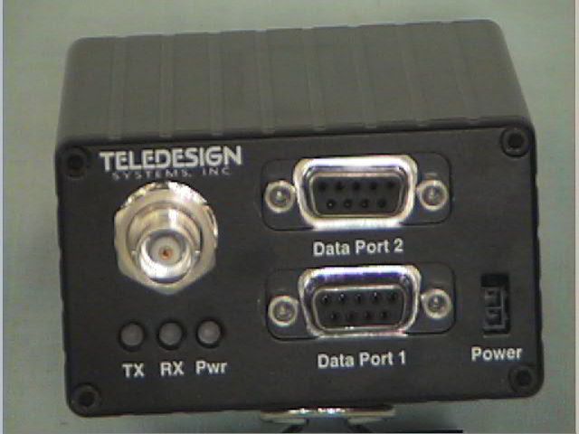
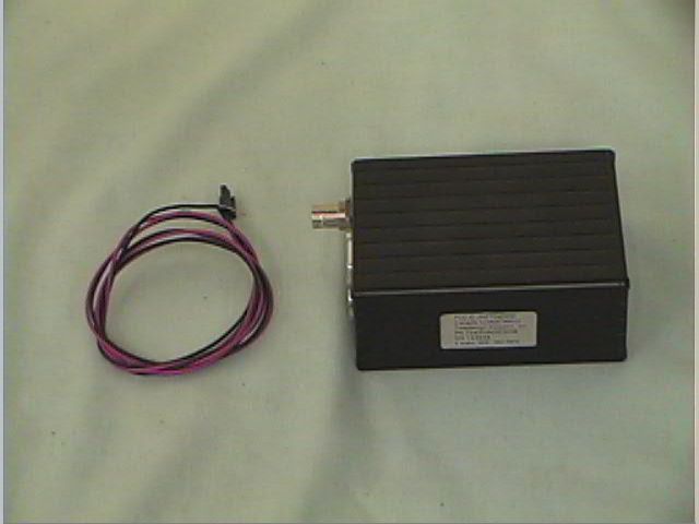
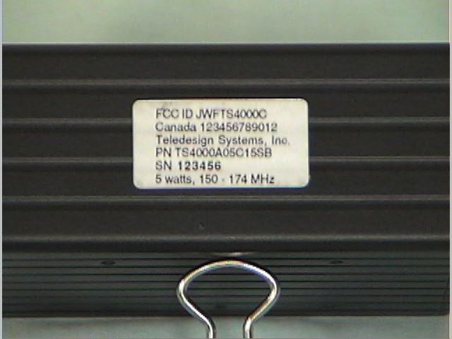
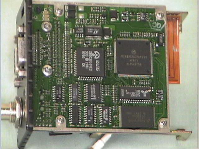
JWFTS4000CRadio Modem with 3422 Transceiver
Teledesign Systems Inc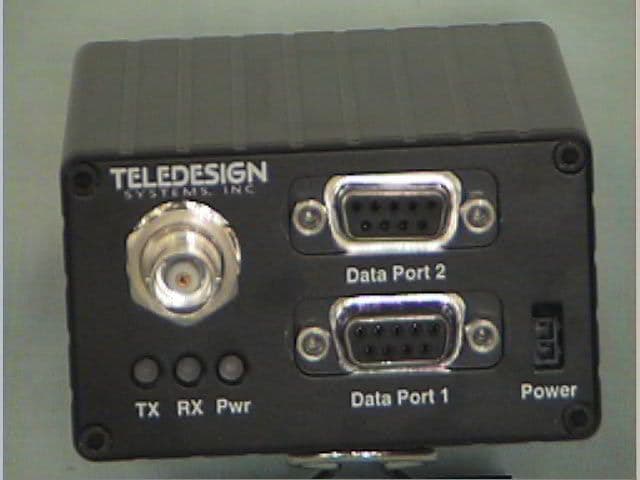
Click to zoom
Application Details
- Equipment Class
- TNB - Licensed Non-Broadcast Station Transmitter
- Date of Grant
- Apr 04, 1999
- Application Purpose
- Original Equipment
- Date of Application
- Feb 02, 1999
- Equipment Note
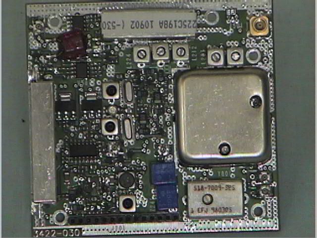
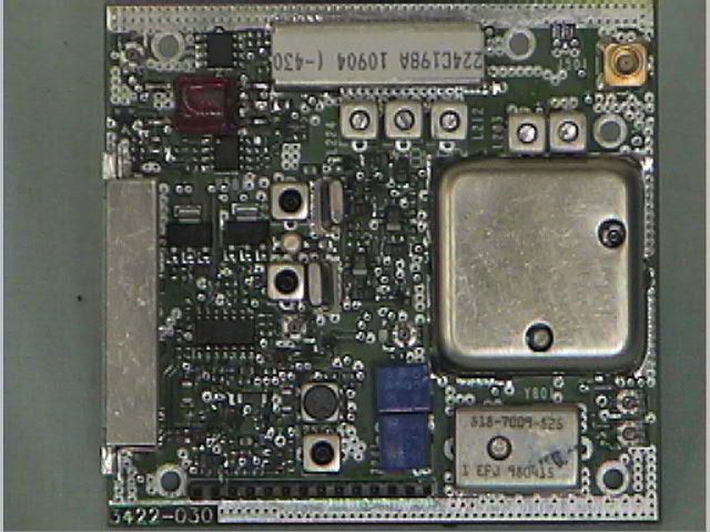
- Radio Modem with 3422 Transceiver
- Frequency Range
- 132.00000000 - 174.00000000
- Company
- Teledesign Systems Inc
- Country
- United States
Documents & Files
Document Text
Text extracted from the exhibit documents filed with the FCC. Open a document above to read the original.
Users Manual
TS4000 Radio Modem User’s Manual Version 4.00G November 1998 2635 North First Street, Suite 205 San Jose, CA 95134-2032 (408) 232-0180 (800) 663-3674 (408) 232-0188 Fax www.teledesignsystems.com [email protected] [email protected] [email protected] This document is copyrighted by Teledesign Systems Inc. with all rights reserved. No part of this document may be reproduced in any form without the prior written consent of Teledesign Systems Inc. Copyright 1995 - 1998 by Teledesign Systems Inc. All rights reserved. This manual has been thoroughly reviewed for accuracy, and every effort has been made to ensure that the information is accurate and complete. However, different versions of this product have different features and capabilities, and this manual reflects only one of those versions. Therefore, Teledesign Systems Inc. assumes no responsibility for errors, omissions or defects in this material, and shall not be liable for any damages resulting from their use. The information in this document is subject to change without notice. TELEDESIGN SYSTEMS INC. MAKES NO WARRANTY OF ANY KIND WITH RESPECT TO THIS DOCUMENT AND SOFTWARE, EITHER EXPRESSED OR IMPLIED, INCLUDING WITHOUT LIMITATION ANY IMPLIED WARRANTIES OF MERCHANTABILITY OR FITNESS FOR A PARTICULAR PURPOSE. Copyright Disclaimer TS4000 Radio Modem User’s Manual Emissionsiii Emissions The TS4000 has been tested and found to comply with the limits for a Class B digital device, pursuant to Part15 of the FCC rules (Code of Federal Regulations 47CFR Part 15). Operation is subject to the condition that this device does not cause harmful interference. The TS4000 has been type accepted for operation by the FCC in accordance with Part 90 of the FCC rules (47CFR Part 90). See the label on the unit for the specific FCC ID and any other certification designations. The TS4000 has been type accepted for operation by the FCC in accordance with Part 101 of the FCC rules (47CFR Part 101). See the label on the unit for the specific FCC ID and any other certification designations. This Class B digital apparatus meets all requirements of the Canadian Interference-Causing Equipment Regulations. The TS4000 has been certified for operation by Industry Canada in accordance with RSS-119 and RSS-210 of the Industry Canada rules. See the label on the unit for the specific Industry Canada certification number and any other certification designations. Changes or modifications not expressly approved by Teledesign Systems Inc. could void the user’s authority to operate this equipment. Shielded cable must be used with this equipment in order to ensure that it meets the emissions limits for which it was designed. It is the responsibility of the user to obtain and use good quality shielded cables with this device. Shielded cables are available from most retail and commercial suppliers of cables designed to work with radio equipment and personal computer peripherals. The frequency band from 406.0 to 406.1 MHz is reserved for use by distress beacons. As such, the TS4000 should not be programmed to transmit on any frequency within this band. Caution should be used when programming frequencies into the TS4000 to eliminate the possibility of TS4000 users interfering with rescue operations on this band. In order to ensure the safe operation of this radio equipment, the following practices should be observed. • DO NOT operate radio equipment near electrical blasting caps or in an explosive atmosphere. • DO NOT operate any radio transmitter unless all RF connectors are secure and any open connectors are properly terminated. • DO NOT allow the antenna to come close to, or touch, the eyes, face, or any exposed body parts while the radio is transmitting. FCC Part 15 Part 90 Part 101 Industry Canada ICES-003 RSS-119 Notice 406.0 to 406.1 MHz Operation Safety Warning TS4000 Radio Modem User’s Manual Table of Contentsiv Table of Contents Emissions...................................................................................................... iii FCC .................................................................................................... iii Industry Canada ................................................................................. iii Notice ...................................................................................................... iii 406.0 to 406.1 MHz Operation ............................................................... iii Safety Warning ....................................................................................... iii Table of Contents ......................................................................................... iv TS4000 Overview ........................................................................................... 1 Introduction ............................................................................................. 1 Features ................................................................................................... 1 Radio Modules ........................................................................................ 2 Frequency Bands ............................................................................... 2 Transmit Power .................................................................................. 2 Channel Spacing and Bandwidth ....................................................... 3 Enclosure................................................................................................. 3 Standard ............................................................................................. 3 Watertight ........................................................................................... 3 Connections ............................................................................................ 3 Serial Port........................................................................................... 3 Antenna Connector........................…
Text truncated - open the document above for the full version.
Users Manual
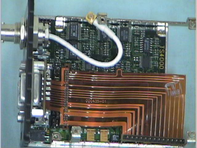
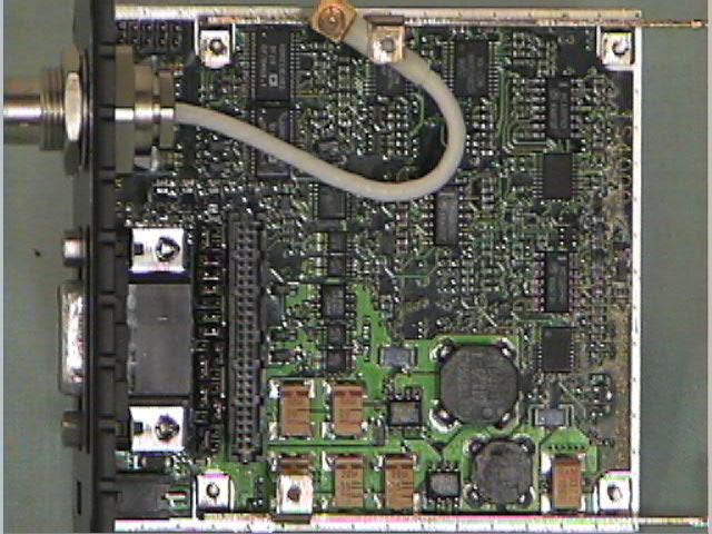
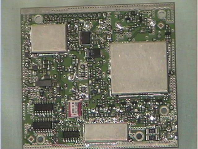
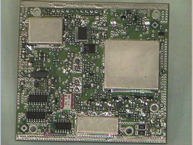
Type Acceptance Information for TS4000 Radio Modem with 3422 Transceiver Proposed FCC ID JWFTS4000C Teledesign Systems, Inc Confidential InformationPage 1 PURPOSE The purpose of this document is to provide information in support of type acceptance testing and report generation in pursuit of a Grant of Equipment Authorization under FCC Parts 15 and 90 and Industry Canada RSS-119, RSS-210 and ICES-003 for Teledesign’s TS4000 Radio Modem. INTRODUCTION The TS4000 is a high-speed radio modem that consists of a modem board, radio transceiver board and metal enclosure. The radio transceiver board connects to the modem board with a flexible printed circuit. Radio Transceiver Board The radio transceiver board for this application is an E.F. Johnson DL3422. This device is being used without any modifications. The DL3422 has received FCC type acceptance with an FCC ID of ATH2423422-007. All circuit descriptions and details for the radio transceiver can be found in the type acceptance document for the DL3422. A copy of this has been included with this application. The radio transceiver is available in a frequency range from 132-174 MHz and includes a temperature stable reference oscillator with a frequency stability of ± 2.5 PPM. Modem Board The modem board provides the serial data interfaces that the user’s equipment interfaces to. The modem board also controls the operation of the radio transceiver. This control includes controlling the radio power and frequency and also controlling the modulation, data rate and frequency deviation of the transmit signal. Note that it is this transmit signal that defines the emission bandwidth and spectral efficiency. Radio Flex Circuit A flex circuit is used to interconnect the radio transceiver board to the modem board. This flex circuit is also used to interconnect the serial port 2 connector to the modem board. The J11 interconnecting diagram included with the modem board schematic provides the specific connections provided by the flex circuit for connecting the radio transceiver to the modem board. Configuration Software IBM compatible configuration software is used to control all aspects of configuration, tune up and test of the TS4000 radio modem. General Information Manufacturer:Teledesign Systems Inc. 2635 North First Street, Suite 205 San Jose, CA 95134 408-232-0180 Contact Person:Mark Hubbard Product Trade Name:TS4000 Radio Modem Product Model Number:TS4000-05Cff where: ff - indicates frequency range Proposed FCC ID:FCC ID: JWFTS4000C Production Plans:Teledesign Systems Inc. plans to produce this product in quantity (greater than 1) production runs. Radio Transceiver Manufacturer:E.F. Johnson Type Acceptance Information for TS4000 Radio Modem with 3422 Transceiver Proposed FCC ID JWFTS4000C Teledesign Systems, Inc Confidential InformationPage 2 Radio Transceiver Model Number:DL3422 Radio Transceiver Part Number:242-3422 (± 2.5 PPM frequency stability) Radio Transceiver FCC ID:ATH2423422-007 Frequency Range:132 - 174 MHz Maximum RF Power Rating:5 watts RF Power Range:0.1 - 5.0 watts, software selectable Method of Modulation:Direct FM Types of Modulation:4 Level FSK GMSK with BT = 0.3 GMSK with BT = 0.5 Type of Emissions:20K0F1D (multi-bandwidth mode) 16K0F1D (multi-bandwidth mode) 11K2F1D (single bandwidth mode) 6K00F1D (for subparts 90.63(d)(7), 90.65(c)(18), 90.67(c)(14), 90.73(d)(13), 90.75(c)(19) and 90.79(d)(6) only). Emission Designator Calculations: Modulation Types: The TS4000 is designed to use three modulation types: 4 level FSK, GMSK with a BT=0.5 and GMSK with a BT=0.3. The 4 level FSK modulation is provided to allow a high spectral efficiency for a given channel bandwidth. The GMSK modulations are provided in order to be compatible with other products and data communications standards. Channel Bandwidths: Our goal is to certify the TS4000 at four different channel bandwidths: 20K0, 16K0, 11K2 and 6K00 (the use of the 6K00 bandwidth is limited to the subparts shown above). This is to allow the TS4000 to be setup for the most efficient operation for a given channel bandwidth that a user is licensed for. 4 Level FSK20K0F1D: Channel Baud Rate (B) = 32000 bps Modulation Frequency (M) = B (1/8) = 4000 Hz Peak Deviation (D) = 6000 Hz Bandwidth Calculation = 2 (D) + 2 (M) Bandwidth Calculation = 2 (6000) + 2 (4000) Bandwidth Calculation = 12000 + 8000 Bandwidth Calculation = 20000 or 20K0 16K0F1D: Channel Baud Rate (B) = 24000 bps Modulation Frequency (M) = B (1/8) = 3000 Hz Type Acceptance Information for TS4000 Radio Modem with 3422 Transceiver Proposed FCC ID JWFTS4000C Teledesign Systems, Inc Confidential InformationPage 3 Peak Deviation (D) = 5000 Hz Bandwidth Calculation = 2 (D) + 2 (M) Bandwidth Calculation = 2 (5000) + 2 (3000) Bandwidth Calculation = 10000 + 6000 Bandwidth Calculation = 16000 or 16K0 11K2F1D: Channel Baud Rate (B) = 15000 bps Modulation Frequency (M) = B (1/8) = 1875 Hz Peak Deviation (D) = 3750 Hz Bandwidth Calculation = 2 (D) + 2 (M) Bandwidth Calculation = 2 (3750) + 2 (1875) Bandwidth Calculation = 7500 + 3750 Bandwidth Calculation = 11250 or 11K2 6K00F1D: (for subparts 90.63(d)(7), 90.65(c)(18), 90.67(c)(14), 90.73(d)(13), 90.75(c)(19) and 90.79(d)(6)). Channel Baud Rate (B) = 4800 bps Modulation Frequency (M) = B (1/8) = 600 Hz Peak Deviation (D) = 1800 Hz Bandwidth Calculation = 2 (D) + 2 (M) Bandwidth Calculation = 2 (1800) + 2 (600) Bandwidth Calculation = 3600 + 1200 Bandwidth Calculation = 4800 or 4K80 GMSK with BT = 0.320K0F1D: Channel Baud Rate (B) = 19200 bps Modulation Frequency (M) = B (1/3) = 6400 Hz Peak Deviation (D) = 3600 Hz Bandwidth Calculation = 2 (D) + 2 (M) Bandwidth Calculation = 2 (3600) + 2 (6400) Bandwidth Calculation = 7200 + 12800 Bandwidth Calculation = 20000 or 20K0 16K0F1D: Channel Baud Rate (B) = 19200 bps Modulation Frequency (M) = B (1/3) = 6400 Hz Peak Deviation (D) = 1600 Hz Bandwidth Calculation = 2 (D) + 2 (M) Bandwidth Calculation = 2 (1600) + 2 (6400) Bandwidth Calculation = 3200 …
Text truncated - open the document above for the full version.
ID Label/Location Info
Type Acceptance Information for TS4000 Radio Modem with 3422 Transceiver Proposed FCC ID JWFTS4000C Teledesign Systems, Inc Confidential InformationPage 1 FCC DECLARATION OF CONFORMITY LABEL The Part 15 Declaration of Conformity label attached to each TS4000 is shown below: Teledesign Systems Inc. Tested To Comply With FCC Standards FOR HOME OR OFFICE USE TS4000
Operational Description
Type Acceptance Information for TS4000 Radio Modem with 3422 Transceiver Proposed FCC ID JWFTS4000C Teledesign Systems, Inc Confidential InformationPage 1 OPERATION DESCRIPTION Radio Channel Programming and Switching Up to 99 radio channels can be pre-programmed into the modem board’s non-volatile memory with a PC based programming software. This software is only available to authorized dealers and service centers. The user can switch between pre-programmed channels by sending an ASCII control string through one of the modem board’s serial ports. The frequency of the radio transceiver is controlled by the microcontroller using the SPI port. This port directly controls the PLL (Phase Lock Loop) on the radio transceiver board. The microcontroller monitors the lock condition of this PLL using the lock detect signal from the radio transceiver. Radio Power Control The transmit power is adjustable from 0.1 to 5 watts. The actual value is adjustable by the end user using the TS4000 configuration software but can never be set over the maximum value of 5 watts. The modem board controls the radio power by setting the radio power DAC on the radio transceiver. This DAC is controlled through the radio transceiver’s SPI interface. The maximum value that this circuit can be set for is configured when the unit is tuned up. This prevents the user from setting the output power higher than the maximum allowed. Data Rate and Emission Masks The modulation data rate is controlled by the microcontroller using the clock circuitry (described above). The modulation data rate, combined with deviation, controls the occupied bandwidth of the transmitted signal. The allowed occupied bandwidth depends on the channel bandwidth and the corresponding emission mask of the signal. Please reference the emission designator calculations in the front of this document for the maximum modulation data rate and deviation allowed for each designated emission. The maximum modulation rate that a unit can operate at is configured by Teledesign Systems when a unit is tuned up. The TS4000 configuration software allows the user to adjust the modulation data rate but can never set it above the maximum value that is configured when the unit is tuned up. The deviation is controlled by the modem board based on the modulation data rate that the unit is set for. Spectral Efficiency This equipment is capable of supporting a minimum of 4800 bits per second per 6.25 kHz of channel bandwidth. This allows this equipment to support the latest FCC spectral efficiency requirements.
Operational Description
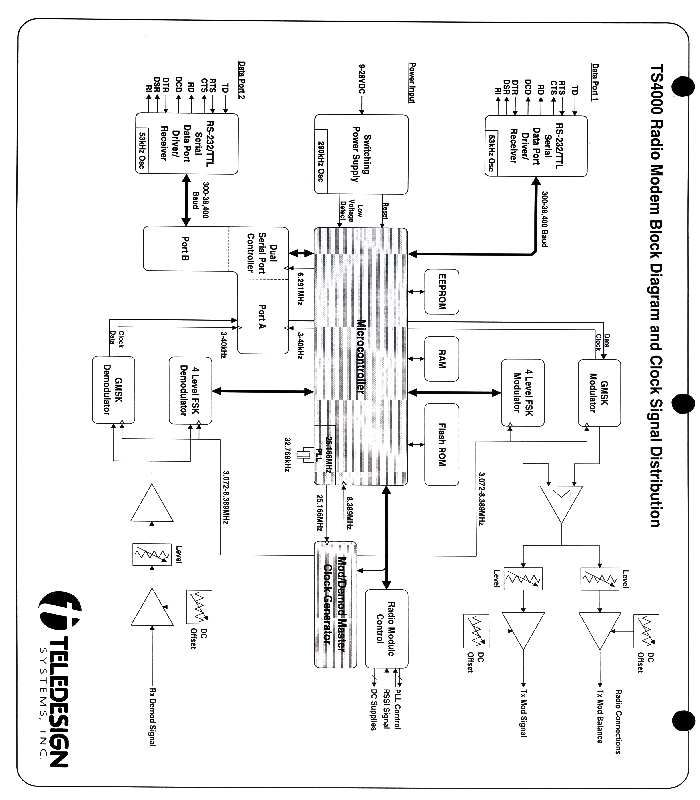
Type Acceptance Information for TS4000 Radio Modem with 3422 Transceiver Proposed FCC ID JWFTS4000C Teledesign Systems, Inc Confidential InformationPage 1 MODEM BOARD CIRCUIT DESCRIPTION Microcontroller and Memory The microcontroller, U16, controls and manages all activity on the modem board. The microcontroller operates at an internal clock rate of 25.1 MHz that is derived from crystal Y1 which oscillates at 32768 Hz. The microcontroller reset is controlled by U2 which monitors the power supply. The program for the microcontroller is stored in flash memory U18. This program can be updated by downloading a new version through the serial port using PC based upgrade software supplied by Teledesign Systems. The chip selects for the flash memory are controlled directly by the microcontroller. The dynamic data for the microcontroller is stored in SRAM (static RAM) U17. Serial EEPROM U15 provides non-volatile storage for the microcontroller. The serial EEPROM is interfaced to the microcontroller through an SPI bus which provides high speed synchronous serial communication. The microcontroller interfaces to a number of other chips on the board through either the SPI bus or through the 16 bit parallel data bus. For the parallel interface, the microcontroller provides all the address decoding for the chip selects. Data Interface There are two serial data interfaces that are used to connect to external equipment. Serial interface 1 is an asynchronous serial interface which is controlled with the SCI (Serial Communications Interface) of the microcontroller. The serial interface lines of the microcontroller are fed into U13 and U27 which provide signal buffering and level translation. The RS-232 buffer, U13, generates its own high (+6 to +10 VDC) and low (-6 to -10 VDC) voltages with a charge pump circuit which oscillates at about 10 kHz. The low voltage of the charge pump is regulated with D5 and is used for some of the analog circuits in the modulation and demodulation sections. The TTL buffering is handled by U27. Serial interface 1 can be configured to operates at either RS-232 or TTL signal levels using jumper block JB1. The RS-232 standard defines voltage signal levels between -25 and +25 volts. TTL signal levels are between 0 and 5 volts. Serial interface 2 is a synchronous or asynchronous serial interface and is controlled with one of the ports of the SCC (Serial Communications Controller) U21. The SCC is controlled by the microcontroller using the parallel bus. To provide the correct parallel interface timing between the SCC and the microcontroller, U25 is used to delay the SCC chip select. Serial interface 2 operates at RS-232 signal levels using U12 to provide signal buffering and level translation. The RS-232 buffer, U12, generates its own high (+6 to +10 VDC) and low (-6 to -10 VDC) voltages with a charge pump circuit which oscillates at about 10 kHz. Power Regulation The power input into the modem can be from 9 to 28 volts DC. This input is diode protected with D22, D23 and D20. The main power regulation is provided by dual switching regulator U20 in conjunction with level adjuster U24. The switching regulator switches at a frequency of approximately 300 kHz. To produce the voltages the switching regulator uses diodes D17, D19, D14, D13, D18 and D21 and transistors Q4 and Q5. The switching regulator produces a 13.0 volt power source and a 5 volt power source. The 13.0 volt power source feeds into the final stage of the radio frequency amplifier of the radio transceiver. The 5 volt power source is used for most of the modem board’s digital circuitry. For the analog circuits, linear regulator U11 produces a temperature and voltage stable 5 volt power source from the 13.0 volt source. Type Acceptance Information for TS4000 Radio Modem with 3422 Transceiver Proposed FCC ID JWFTS4000C Teledesign Systems, Inc Confidential InformationPage 2 Diagnostics The microcontroller monitors a number of signals using an A/D (analog to digital) converter internal to the microcontroller. To prevent over and under voltage into the A/D converter, diodes D15, D16, D6, D7, D8, D9, D10, and D11 are used. To monitor the temperature on the board, U1 is fed into the microcontroller’s A/D converter. To indicate the state of the modem, LEDs DS1, DS2, and DS3 are used. These are controlled by the microcontroller using transistors Q12, Q13, and Q14 to buffer the signals. Clock Circuitry The modem board generates a variable rate modulation clock which controls the over the air data rate of the modulator and demodulator circuits. The modulation clock can be varied between 1 and 10 MHz. The modulation clock is derived from the microcontroller’s main clock. The microcontroller’s main clock is fed into a divider U23 which generates the modulation clock. The divide ratio of U23 is partially set and by latch U19 that is loaded through the SPI bus. The divide ratio is tweaked using decoder U26 and divider U22. The divide ratio of U22 is set through the microcontroller’s SPI port. Modulation and Demodulation ICs U7 and U9 perform the modulation and demodulation of data. The modulation used by the modem board is selectable for GMSK (Gaussian Minimum Shift Keying) or four level FSK (Frequency Shift Keying). This is selectable by the user using the TS4000 configuration software. GMSK When GMSK modulation is used, U9 provides the modulation and demodulation functions. Data is fed into and out of this chip through one port of the SCC (Serial Communications Controller), U21. The GMSK chip filters the transmit waveform by passing NRZ (Non-Return to Zero) data through a Gaussian low pass filter with a BT of 0.5. The BT of 0.5 indicates that the 3 dB bandwidth of the Gaussian filter is 0.5 of the bit rate. Q7 and Q6 are used to adjust the demodulation performance of U9. Four Level FSK When 4LFSK (Four Level Frequency Shift Keying) modulation is used, U7 provides the modulation and demodulation functions. Data is fed into and out of th…
Text truncated - open the document above for the full version.
Operational Description
Type Acceptance Information for TS4000 Radio Modem with 3422 Transceiver Proposed FCC ID JWFTS4000C RADIO FLEX CIRCUIT CONNECTIONS TS4000 50-Pin J11 Radio Interface Connector3422 Transceiver Level TypeFunctionPinPinFunctionTypeLevel 14-Pin I/O Ground 50 49 Ground 0-5VDCD/ARF Power Control 48 47 Tx Mod BalanceD/A0-5VDC 0-5VDCA/DReflective Power 46 45 Forward PowerA/D0-5VDC14 0.5-4Vpp AnaRx Ext Signal Out 44 43 Rx Demod InAna0.02- 4Vpp 13 0-5VDCD/AReceive Tune 42 41 RSSIA/D0-5VDC12 0.5-2Vpp AnaTx Ext Signal In 40 39 Tx Mod OutAna0-5Vpp6 Ground 38 37 Ground 5V CMOS I/OCPU I/O 36 35 SPI Diagnstc EnableI/O 5V CMOS11 RS-232 SIO-2RI 34 33 SPI Data InI/O 5V CMOS RS-232 SIO-2RI 32 31 SPI ClockI/O 5V CMOS10 RS-232 SIO-2TxCLK/DTR 30 29 SPI Data OutI/O 5V CMOS9 RS-232 SIO-2CTS 28 27 SPI Synth EnableI/O 5V CMOS8 RS-232 SIO-2TD 26 25 Synth Lock DetectI/O 5V CMOS7 RS-232 SIO-2RTS 24 23 PTTOOpn Drain RS-232 SIO-2RD 22 21 Continuous +5Pwr5VDC RS-232 SIO-2RxCLK/DSR 20 19 Transmit +5/EnablePwr/O5VDC5 RS-232 SIO-2DCD 18 17 Receive +5/EnablePwr/O5VDC4 Ground 16 15 Ground 0-B+VDC D/ATransmit B+ 14 13 Transmit B+D/A 0-B+VDC3 7-13VDC PwrB+ 12 11 B+Pwr 7-13VDC2 7-13VDC PwrB+ 109 B+Pwr 7-13VDC2 9-28VDC Pwr InDC Power 87 DC PowerPwr In 9-28VDC 9-28VDC Pwr InDC Power 65 DC PowerPwr In 9-28VDC Ground 43 Ground1 Ground 21 Ground1
Test Report
i APPLICATION FOR FCC PART 90 TYPE ACCEPTANCE Teledesign Systems Inc. Radio Modem with 3422 Transceiver Model No.: TS4000-05Cff FCC ID: JWFTS4000C Report # J98033454C Date of Report: December 21, 1998 Total No. of Pages Contained in this Report: 73 This report shall not be reproduced except in full, without written approval of Intertek Testing Services. This report must not be used to claim product endorsement by NVLAP or any agency of the U.S. Government. The results contained in this report were derived from measurements performed on the identified test samples. Any implied performance of other samples on this report is dependent on the representative of the samples tested. FCC Part 90 Type Acceptance INTERTEK TESTING SERVICES - Menlo Park Teledesign Radio Modem with 3422 TransceiverDate of Test: December 18, 1998 ii FCC ID: JWFTS4000C Report # J98033454C Table of Contents 1.0Introduction.........................................................1 1.1Test Summary..................................................1 1.2Product Description..............................................2 1.3Related Submittal(s) Grants........................................2 2.0RF Power Output.....................................................3 2.1Test Procedure..................................................3 2.2Test Equipment.................................................3 2.3Test Results....................................................3 3.0Effective Radiated Power..............................................7 3.1Test Procedure..................................................7 3.2Test Equipment.................................................7 3.3Test Results....................................................7 4.0Occupied Bandwidth, Bandwidth Limitation, Emission Masks...................9 4.1Test Procedure..................................................9 4.2Test Equipment.................................................9 4.3Test Results....................................................9 5.0Spurious Emissions at Antenna Terminals................................34 5.1Test Procedure.................................................34 5.2Test Equipment................................................34 5.3Test Results...................................................34 6.0Field Strength of Spurious Radiation....................................45 6.1Test Procedure.................................................45 6.2Test Equipment................................................45 6.3Test Results...................................................46 7.0Line Conducted Emissions............................................50 7.1Test Procedure.................................................50 7.2Test Results...................................................51 8.0Frequency Stability vs Temperature.....................................55 8.1Test Procedure.................................................55 8.2Test Equipment................................................55 8.3Test Results...................................................55 9.0Frequency Stability vs Voltage.........................................56 9.1Test Procedure.................................................56 9.2Test Equipment................................................56 9.3Test Results...................................................56 INTERTEK TESTING SERVICES - Menlo Park Teledesign Radio Modem with 3422 TransceiverDate of Test: December 18, 1998 iii FCC ID: JWFTS4000C Report # J98033454C 10.0Transient Frequency Behavior.........................................57 10.1Test Procedure.................................................57 10.2Test Result....................................................58 INTERTEK TESTING SERVICES - Menlo Park Teledesign Radio Modem with 3422 TransceiverDate of Test: December 18, 1998 1 FCC ID: JWFTS4000C Report # J98033454C 1.0Introduction 1.1Test Summary FCC RULEDESCRIPTION OF TESTRESULPAGE T 2.985(a)RF Power OutputPass3 90.205Effective Radiated PowerPass4 2.989(i), 90.209(b)(5),Occupied Bandwidth, BandwidthPass5 90.210, 90.63(d)(7),Limitation, Emission Masks 90.65(c)(18), 90.67(c)(14), 90.73(d)(13), 90.75(c)(19), 90.79(d)(6) 2.991, 90.210Spurious Emissions at Antenna TerminalsPass8 2.993, 15.109, 90.210Field Strength of Spurious RadiationPass10 15.107Line Conducted EmissionsPass13 2.995(a)Frequency Stability vs. TemperaturePass16 2.995(d)(3)Frequency Stability vs. VoltagePass17 90.214Transient Frequency BehaviorPass18 February 2, 1999 Xi-Ming YangDate Test Engineer INTERTEK TESTING SERVICES - Menlo Park Teledesign Radio Modem with 3422 TransceiverDate of Test: December 18, 1998 FCC ID: JWFTS4000C Report # J98033454C 2 1.2Product Description The unit under test is a radio modem with 3422 transceiver.. For more details, see attached information. 1.3Related Submittal(s) Grants [X] Type acceptance granted for the radio transceiver (see attached) used in this radio modem. Applicant: Johnson Data Telemetry Corporation FCC ID: ATH2423422-007 Date of Grant: December 10, 1996 File No.: 31010/EQU 17.9 [X]DOC for computer section, a separate DOC is prepared. INTERTEK TESTING SERVICES - Menlo Park Teledesign Radio Modem with 3422 TransceiverDate of Test: December 18, 1998 FCC ID: JWFTS4000C Report # J98033454C 3 2.0RF Power Output, FCC §2.985(a) 2.1Test Procedure The transmitter output was connected to a calibrated coaxial attenuator, the other end of which was connected to a spectrum analyzer. The resolution bandwidth and the video bandwidth of the spectrum analyzer were set up to 300 kHz and 300 kHz respectively. The attenuator was included in spectrum analyzer OFFSET function. Transmitter output was read off the spectrum analyzer in dBm. 2.2Test Equipment Hewlett Packard 8481A Power Sensor, 435B Power Meter Hewlett Packard HP8566B Spectrum Analyzer, 100 Hz - 22 GHz Tektronix 2782 Spectrum Analyzer, 100 Hz - 40 GHz 2.3Test Results Refer to the attached plot #2.1-2.3 and table below: Power LevelReadi…
Text truncated - open the document above for the full version.
Test Report
i A APPLICATION FOR FCC PART 90 TYPE ACCEPTANCE Teledesign Systems Inc. Radio Modem with 3422 Transceiver Model No.: TS4000-05Cff FCC ID: JWFTS4000C Report # J98033454C Date of Report: December 21, 1998 Total No. of Pages Contained in this Report: 73 This report shall not be reproduced except in full, without written approval of Intertek Testing Services. This report must not be used to claim product endorsement by NVLAP or any agency of the U.S. Government. The results contained in this report were derived from measurements performed on the identified test samples. Any implied performance of other samples on this report is dependent on the representative of the samples tested. FCC Part 90 Type Acceptance INTERTEK TESTING SERVICES - Menlo Park Teledesign Radio Modem with 3422 TransceiverDate of Test: December 18, 1998 ii FCC ID: JWFTS4000C Report # J98033454C Table of Contents 1.0Introduction.........................................................1 1.1Test Summary..................................................1 1.2Product Description..............................................2 1.3Related Submittal(s) Grants........................................2 2.0RF Power Output.....................................................3 2.1Test Procedure..................................................3 2.2Test Equipment.................................................3 2.3Test Results....................................................3 3.0Effective Radiated Power..............................................7 3.1Test Procedure..................................................7 3.2Test Equipment.................................................7 3.3Test Results....................................................7 4.0Occupied Bandwid…
Text truncated - open the document above for the full version.
Contact Information
Applicant
Bruce Delevaux(Vice President)
Technical Contact
Intertek Testing ServicesDavid Chernomordik
(650) 463-2900
1365 Adams Court · Menlo Park, California · United States
Non-Technical Contact
Teledesign Systems Inc.Mark Hubbard
(408) 232-0180
Test Firm
Intertek Testing Services NA Inc.John Quigley
Technical Specifications
| # | Rule Parts | Frequency Range | Power Output | Emission | Tolerance |
|---|---|---|---|---|---|
| 4 | 90.21 | 132 MHz - 174 MHz | 5 W | 6K00F1D | 2.5 ppm |
Other Applications from Teledesign Systems Inc
JWFTS4000GL
Oct 28, 2012Radio Modem
Equipment Class
TNB - Licensed Non-Broadcast Station Transmitter
JWFTS4000GH
Oct 28, 2012Radio Modem
Equipment Class
TNB - Licensed Non-Broadcast Station Transmitter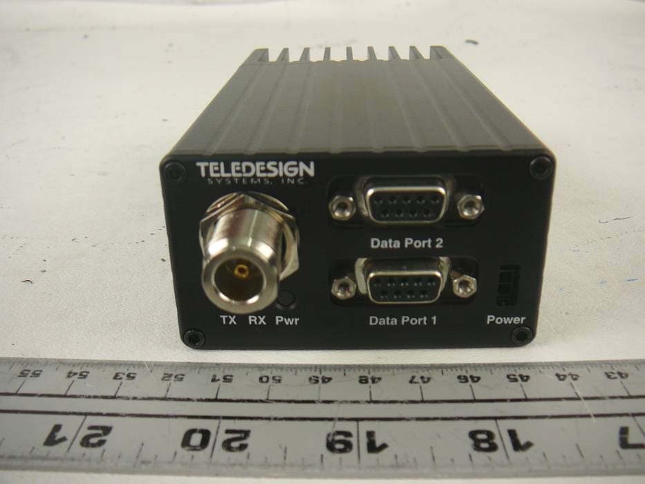
JWFTS4000EL
Apr 06, 2012Radio Modem
Equipment Class
TNB - Licensed Non-Broadcast Station Transmitter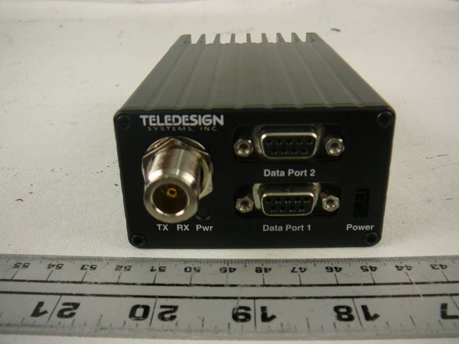
JWFTS4000EH
Apr 06, 2012Radio Modem
Equipment Class
TNB - Licensed Non-Broadcast Station Transmitter
JWFTS4000B
Apr 05, 1999Radio Modem with 3412 Transceiver
Equipment Class
TNB - Licensed Non-Broadcast Station Transmitter