JWSB78RF Laser Basestation
Worthdata Inc
Click to zoom
Application Details
- Equipment Class
- DSS - Part 15 Spread Spectrum Transmitter
- Date of Grant
- Jan 25, 2006
- Application Purpose
- Original Equipment
- Date of Application
- Jan 25, 2006
- Equipment Note
- RF Laser Basestation
- Frequency Range
- 903.00000000 - 927.00000000
- Company
- Worthdata Inc
- Country
- United States
Documents & Files
Document Text
Text extracted from the exhibit documents filed with the FCC. Open a document above to read the original.
Users Manual
Table Of Contents Introduction .....................................................................................................2 Installation .......................................................................................................3 Configuring the RF Laser Reader .................................................................8 Radio Considerations....................................................................................24 Operating Instructions .................................................................................24 Accumulate Mode..........................................................................................25 Function/Control Key Support ....................................................................26 Troubleshooting.............................................................................................28 Changing Jumpers and Channels ................................................................32 Recharging the Batteries ..............................................................................34 Specifications for Code 39 ............................................................................35 Code 93 Specifications ..................................................................................38 Codabar Specifications .................................................................................39 Code 128 Specifications ................................................................................40 Interleaved 2 of 5 Code .................................................................................42 UPC Specifications ........................................................................................44 MSI/Plessey Specifications ...........................................................................48 Index...............................................................................................................50 1/06 1 The LZ400-RF and the B78 Base Station have been tested and found to comply with the limits for a Class A digital device, pursuant to Part 15 of the FCC Rules. These limits are designed to provide reasonable protection against harmful interference in a residential installation. This equipment generates, uses and can radiate radio frequency energy and, if not installed and used in accordance with the instructions, may cause harmful interference to radio communications. However, there is no guarantee that interference will not occur in a particular installation. If this equipment does cause harmful interference to radio or television reception, which can be determined by turning the equipment off and on, the user is encouraged to try to correct the interference by one or more of the following measures: • Reorient or relocate the receiving antenna. • Increase the separation between the equipment and receiver. • Connect the equipment into an outlet on a circuit different from that to which the receiver is connected. • Consult the dealer or an experienced radio/TV technician for help. Shielded cables and I/O cords must be used with this equipment to comply with the relevant FCC regulations. Changes or modifications not expressly approved in writing by Worth Data may void the user's authority to operate this equipment. This device complies with Part 15 of the FCC Rules. Operation is subject to the following two conditions: (1) this device may not cause harmful interference, and 2) this device must accept any interference received, including interference that may cause undesired operation. This device complies with RSS-210 of Industry Canada. Operation is subject to the following two conditions: 1) this device may not cause interference, and 2) this device must accept any interference, including interference that may cause undesired operation of the device. The laser used is a Class II Laser Product and has a 1.2 Milliwatts Output. To operate the laser scanner, aim the scanner at the bar code, and pull the trigger. The light source will turn off, once a successful scan has occurred or 2.5 seconds has elapsed, whichever is first. Do not look directly into the laser light source with the trigger depressed; avoid direct eye contact with the laser light source. 2 Introduction The Worth Data RF Lasers have the following features: 1) The LZ400-RF Laser Scanner for the USA and Canada. This laser has a range of 500 feet and has collision detect and retry logic built within. The LZ400-RF Laser communicates with the B78 Base Station. The Base Station communicates with a host PC through the USB port or a RS-232 Serial Port. Up to ten RF Lasers can communicate with one Base Station. 2) If you use the USB interface, data is transmitted as keyboard data. If you use the serial interface instead, serial data is transmitted to one of the computer's COM ports. 3) The USA RF Laser and Base operate in the 902MHz band. The laser and base radios operate by "frequency hopping" spread spectrum. The radios hop from one frequency to another every 400ms. The radio goes through 25 different frequencies and then repeats the sequence – all in the 902 MHz band at 15 milliwatts (10 dBm) of power. Different sequences define the channels. It is possible to have up to ten RF Lasers/Base Stations in the same area, providing each pair is on separate channels to avoid interference and general confusion. The RF Lasers can also operate in the same room as the 701 RF Terminal. 4) The R/F Lasers can read and discriminate between Code 39, Full ASCII Code 39, Interleaved 2 of 5, Codabar, Code 128, EAN-13, EAN-8, UPC- E, UPC-E1, UPC-A, MSI, LabelCode4, LabelCode5, Code 93 and Plessey. 5) The RF Lasers have a rechargeable lithium ion battery. The battery is recharged with an included 5v power supply. Recharge time on fully discharged batteries is 2 hours. 3 Installation Components of RF Laser Readers In the event the shipping box shows damage on arrival, please note the damage on the carrier's receipt log. The supp…
Text truncated - open the document above for the full version.
Cover Letter(s)
623 SWIFTST. • SANTACRUZ, CA 95060 • TELEPHONE: 831-458-9938 • FAX: 831-458-9964 • EMAIL: [email protected]
Cover Letter(s)
1 Helen Zhao Subject: FW: answer: TCB questions: (Revised) WORTHDATA INC., FCC ID: JWSB78, Assessment NO.: AN06T5408, Notice#2 05U3728-1B FCC 900 Report_ Ba... 05U3728-2B IC 900 Report_Base ... From: Claire Hoque Sent: Thursday, January 26, 2006 1:52 PM To: Helen Zhao Cc: Michael Heckrotte; Chuck Cowden; Thu Chan Subject: answer: TCB questions: (Revised) WORTHDATA INC., FCC ID: JWSB78, Assessment NO.: AN06T5408, Notice#2 Hi Helen, Here are the answers. Question #1: The setup photos show the device was tested with case removed, please provide more internal photos to show the construction of the case. Please also confirm the material the case is made of, and justify the test condition is the worst case to catch maximum emissions. <answer>the enclosure is made of plastic and it should not have any effect on an emissions signal. Question #2: Pease update the report in the following areas: a) In section 7.1.2, 7.1.4, only test plots are provided, no final test data as well as limit shown in test result. b) In section 7.1.5, no test plots were provided. <answer>pls see revised FCC/IC reports. Thanks, Claire
ID Label/Location Info
PROPOSED FCC ID LABEL AND LOCATION WORTH DATA, INC. This device complies with Part 15 of the FCC Rules. Operation is subject to the following two conditions: (1) this device may not cause harmful interference, and (2) this device must accept any interference received, including interference that may cause undesired operation. FCC ID: JWSB78 FCC ID LABEL
Parts List/Tune Up Info
The JJB Series packs near the performance of a con- ventional monopole into an incredibly compact quarter- inch (7mm) diameter package. These antennas are ideal for any OEM application requiring a compact, cosmetically-attractive, low-cost antenna solution. The antenna features a through-hole feedline that can attach directly to a user’s PCB. Internal or external mounting is possible. Features Electrical Specifications Ultra-compact Very low cost Low VSWR Excellent performance Omni-directional pattern Easily concealed internally Suitable for internal or external applications Use with plastic* or metal enclosures ANT-916-JJB-xx DATA SHEET Product DimensionsDescription Plots 0.28” (7.0) Antenna Factor575 S.E. Ashley Place Grants Pass, OR 97526-3237 www.antennafactor.com 541-956-0931 (phone) 541-471-6251 (fax) Rev 08-09-05 AzimuthElevationTypical VSWR 270 90 180 0 -30dB -25dB -20dB -15dB -10dB - 5dB 0dB 5dB 10dB 270 90 180 0 -30dB -25dB -20dB -15dB -10dB - 5dB 0dB 5dB 10dB Coming Soon Coming Soon Coming Soon Coming Soon S11 SWR 1.877 CENTER 916.000MHz ST CENTER 916.000MHz RA SPAN 100.000MHz 1.586 * Requires proximity ground plane 0.69” (17.6) 0.34” (8.6) 0.08” (2.0) 0.35” (9.0) 0.22” (5.5) 0.57” (14.5) 0.22” (5.5) 0.06” (1.5) Center Freq. Bandwidth Wavelength VSWR Impedance Gain Connection 916MHz 30MHz 1/4-wave <2.0 typ. at center 50 ohms -1dBi est. Direct solder Electrical Specifications RA electrical specifications and plots measured on 1½” x 3½” reference ground plane Ordering Information ST electrical specifications and plots measured on 3½” x 3½” reference ground plane ANT-916-JJB-RA (Right-Angle) ANT-916-JJB-ST (Straight)
Test Setup Photos
REPORT NO: 05U3728-1 DATE: DECEMBER 19, 2005 EUT: RF LASER BASESTATION FCC ID: JWSB78 Page 57 of 63 COMPLIANCE CERTIFICATION SERVICES DOCUMENT NO: CCSUP4031A 561F MONTEREY ROAD, MORGAN HILL, CA 95037 USA TEL: (408) 463-0885 FAX: (408) 463-0888 This report shall not be reproduced except in full, without the written approval of CCS. 8. SETUP PHOTOS ANTENNA PORT CONDUCTED RF MEASUREMENT SETUP ANTENNA PORT CONDUCTED PHOTO REPORT NO: 05U3728-1 DATE: DECEMBER 19, 2005 EUT: RF LASER BASESTATION FCC ID: JWSB78 Page 58 of 63 COMPLIANCE CERTIFICATION SERVICES DOCUMENT NO: CCSUP4031A 561F MONTEREY ROAD, MORGAN HILL, CA 95037 USA TEL: (408) 463-0885 FAX: (408) 463-0888 This report shall not be reproduced except in full, without the written approval of CCS. RADIATED RF MEASUREMENT SETUP RADIATED FRONT PHOTO REPORT NO: 05U3728-1 DATE: DECEMBER 19, 2005 EUT: RF LASER BASESTATION FCC ID: JWSB78 Page 59 of 63 COMPLIANCE CERTIFICATION SERVICES DOCUMENT NO: CCSUP4031A 561F MONTEREY ROAD, MORGAN HILL, CA 95037 USA TEL: (408) 463-0885 FAX: (408) 463-0888 This report shall not be reproduced except in full, without the written approval of CCS. RADIATED BACK PHOTO REPORT NO: 05U3728-1 DATE: DECEMBER 19, 2005 EUT: RF LASER BASESTATION FCC ID: JWSB78 Page 60 of 63 COMPLIANCE CERTIFICATION SERVICES DOCUMENT NO: CCSUP4031A 561F MONTEREY ROAD, MORGAN HILL, CA 95037 USA TEL: (408) 463-0885 FAX: (408) 463-0888 This report shall not be reproduced except in full, without the written approval of CCS. DIGITAL DEVICE RADIATED EMISSIONS SETUP DIGITAL DEVICE FRONT PHOTO REPORT NO: 05U3728-1 DATE: DECEMBER 19, 2005 EUT: RF LASER BASESTATION FCC ID: JWSB78 Page 61 of 63 COMPLIANCE CERTIFICATION SERVICES DOCUMENT NO: CCSUP4031A 561F MONTEREY ROAD, MORGAN HILL, CA 95037 USA TEL: (408) 463-0885 FAX: (408) 463-0888 This report shall not be reproduced except in full, without the written approval of CCS. DIGITAL DEVICE BACK PHOTO REPORT NO: 05U3728-1 DATE: DECEMBER 19, 2005 EUT: RF LASER BASESTATION FCC ID: JWSB78 Page 62 of 63 COMPLIANCE CERTIFICATION SERVICES DOCUMENT NO: CCSUP4031A 561F MONTEREY ROAD, MORGAN HILL, CA 95037 USA TEL: (408) 463-0885 FAX: (408) 463-0888 This report shall not be reproduced except in full, without the written approval of CCS. POWERLINE CONDUCTED EMISSIONS MEASUREMENT SETUP LINE CONDUCTED FRONT PHOTO REPORT NO: 05U3728-1 DATE: DECEMBER 19, 2005 EUT: RF LASER BASESTATION FCC ID: JWSB78 Page 63 of 63 COMPLIANCE CERTIFICATION SERVICES DOCUMENT NO: CCSUP4031A 561F MONTEREY ROAD, MORGAN HILL, CA 95037 USA TEL: (408) 463-0885 FAX: (408) 463-0888 This report shall not be reproduced except in full, without the written approval of CCS. END OF REPORT LINE CONDUCTED BACK PHOTO
Contact Information
Applicant
Steve Luzovich(Senior Electronics Engineer)
Test Firm
Compliance Certification Services IncSteve Cheng
Technical Specifications
| # | Rule Parts | Frequency Range | Power Output |
|---|---|---|---|
| 1 | 15C | 903 MHz - 927 MHz | 15.80 mW |
Other Applications from Worthdata Inc
JWSLZ400RF
Jan 19, 2006Long Range 2-Way RF Laser Barcode Scanner
Equipment Class
DSS - Part 15 Spread Spectrum Transmitter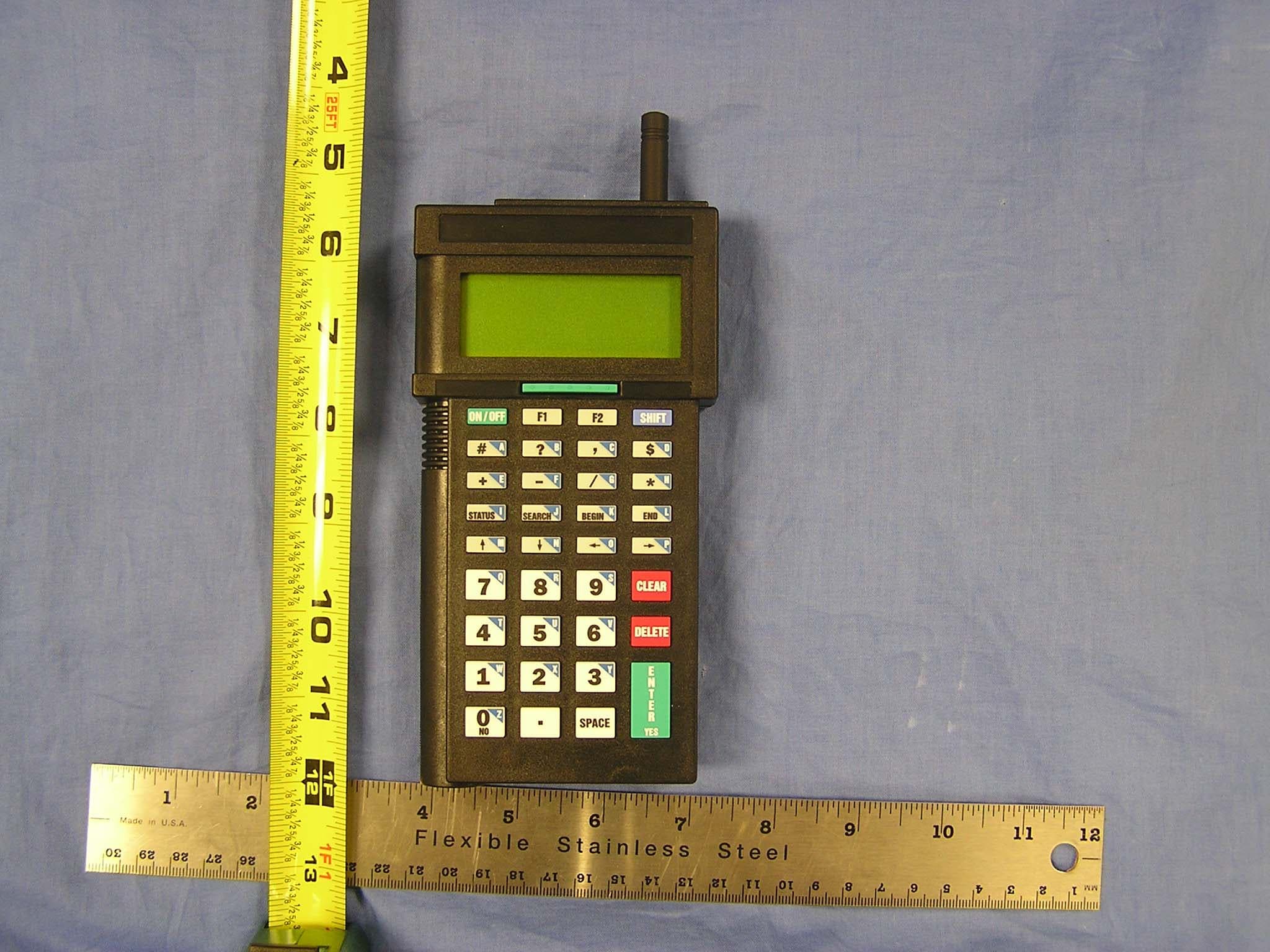
JWSLT802
Nov 02, 2005802.11b Wireless CF Module
Equipment Class
DTS - Digital Transmission System
JWSB551
Dec 01, 2003RF BaseStation
Equipment Class
DSS - Part 15 Spread Spectrum Transmitter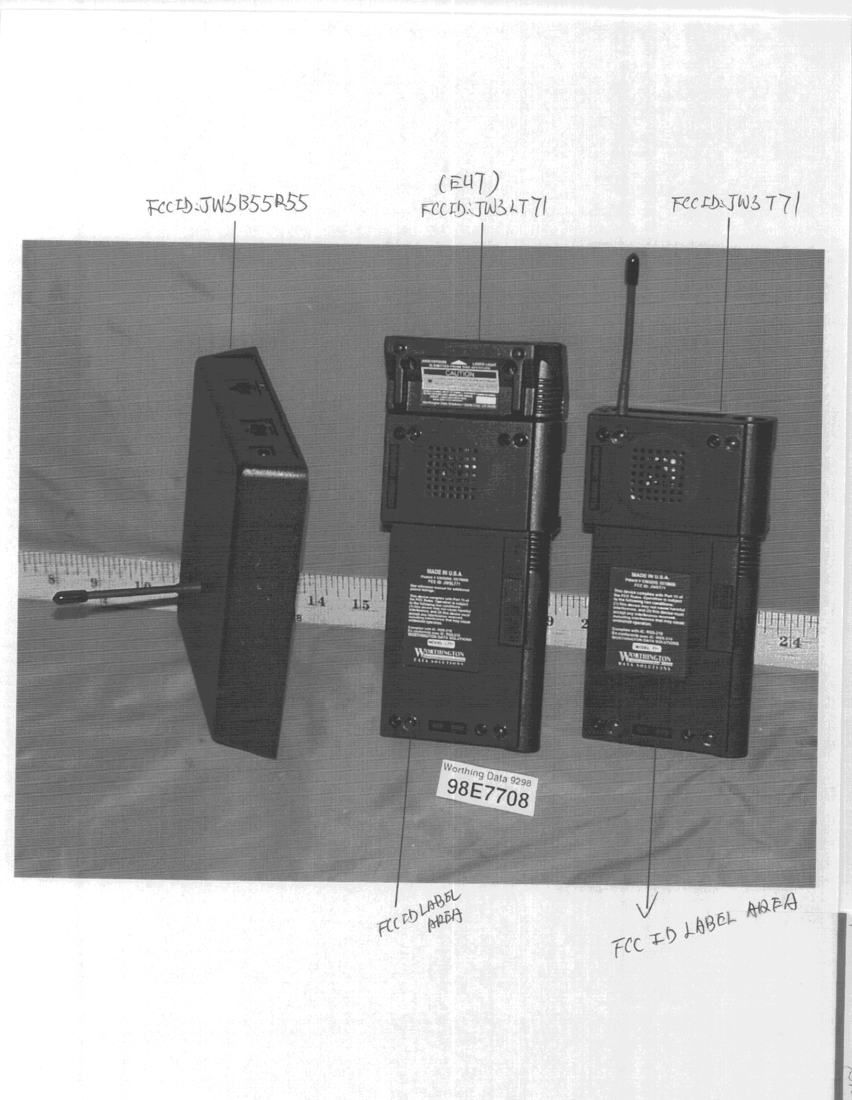
JWSLT71A
Dec 20, 1998DXT - Part 15 Low Power Transceiver, Rx Verified
Equipment Class
DXT - Part 15 Low Power Transceiver, Rx Verified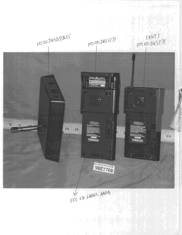
JWST71A
Dec 20, 1998DXT - Part 15 Low Power Transceiver, Rx Verified
Equipment Class
DXT - Part 15 Low Power Transceiver, Rx Verified