JWSLT802802.11b Wireless CF Module
Worthdata Inc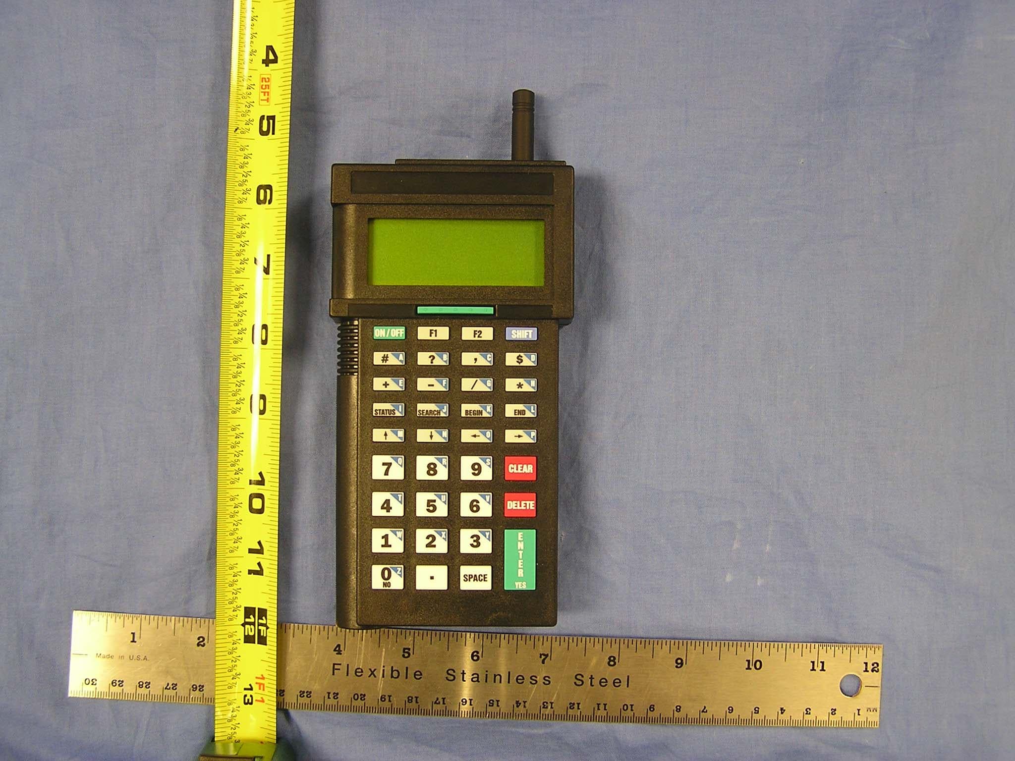
Click to zoom
Application Details
- Equipment Class
- DTS - Digital Transmission System
- Date of Grant
- Nov 02, 2005
- Application Purpose
- Original Equipment
- Date of Application
- Nov 02, 2005
- Equipment Note
- 802.11b Wireless CF Module
- Frequency Range
- 2412.00000000 - 2462.00000000
- Company
- Worthdata Inc
- Country
- United States
Documents & Files
Document Text
Text extracted from the exhibit documents filed with the FCC. Open a document above to read the original.
Users Manual
802 RF Terminal Users Guide Worth Data Inc. September 2005 This equipment has been tested and found to comply with the limits for a Class B digital device, pursuant to Part 15 of the FCC Rules. These limits are designed to provide reasonable protection against harmful interference in a residential installation. This equipment generates, uses and can radiate radio frequency energy and, if not installed and used in accordance with the instructions, may cause harmful interference to radio communications. However, there is no guarantee that interference will not occur in a particular installation. If this equipment does cause harmful interference to radio or television reception, which can be determined by turning the equipment off and on, the user is encouraged to try to correct the interference by one or more of the following measures: • Reorient or relocate the receiving antenna. • Increase the separation between the equipment and receiver. • Connect the equipment into an outlet on a circuit different from that to which the receiver is connected. • Consult the dealer or an experienced radio/TV technician for help. Shielded cables and I/O cords must be used with this equipment to comply with the relevant FCC regulations. Changes or modifications not expressly approved in writing by Worth Data may void the user's authority to operate this equipment. This device complies with Part 15 of the FCC Rules. Operation is subject to the following two conditions: (1) this device may not cause harmful interference, and 2) this device must accept any interference received, including interference that may cause undesired operation. This Class B digital apparatus meets the requirements of the Canadian Interference-Causing Equipment Regulations. Cet appareil numérique de la classe B respecte toutes les exigences du Réglement sur le matériel brouilleur du Canada. The 802 RF Terminal has been approved for use in the United States and Canada as a low power direct sequence spread-spectrum radio operating in the unlicensed 2.4 GHz frequency band. This device is required to comply with FCC RF exposure requirements for mobile and fixed transmitting devices. The FCC requires that the antenna used for this transmitter must be installed to provide a separation of at least 2 cm (.8 inches) from all persons (not including hands, wrists, feet, and ankles) and must not be co- located or operating in conjunction with any other antenna or transmitter. This wireless portable device has been shown to be capable of compliance for localized specific absorption rate (SAR) for General Population/Uncontrolled Exposure limits specified in ANSI/IEEE Std. C95.1-1992 and had been tested in accordance with the measurement procedures specified in FCC OET 65 Supplement C (Edition 01-01). And RSS-102 Issue 1 (Provisional) September 25, 1999. For body worn operation, this device has been tested and meets the FCC RF exposure guidelines for use with F41 Leather Carrying Case and T46 Holster. Use of other carrying cases or holsters may not ensure compliance with FCC RF exposure guidelines. The LT802 model of this product has a laser scanner integrated with the Terminal as one unit. The laser used is a Class II Laser Product and has a 1.2 Milliwatt Output. To operate the laser scanner, aim the top of the case at a bar code, and press the long green key on the keyboard of the R/F Terminal. The light source will turn off, once a successful scan has occurred or 2.5 seconds has elapsed, whichever is first. Do not look directly into the laser light source with the "Scan Key" depressed; avoid direct eye contact with the laser light source. The LTnn models of the RF Terminal as well as the LZ300 and LZ400 Laser Scanners are covered by one or more of the following U.S. Patents: There are no user adjustments or maintenance operations to be performed on the integrated laser scanner. Patent # 4,360,798 4,369,361 4,387,297 4,460,120 4,496,831 4,593,186 4,603,262 4,607,156 4,652,750 4673,805 4,736,095 4,758,717 4,816,660 4,845,350 4,896,026 4,897,532 4,923,281 4,933,538 4,992,717 5,015,833 5,017,765 5,021,641 5,029,183 5,047,617 5,103,461 5,113,445 5,140,144 5,142,550 5,149,950 5,157,687 5,168,148 5,168,149 5,180,904 5,229,591 5,230,088 5,235,167 5,243,655 5,247,162 5,250,791 5,250,792 5,262,627 5,280,163 5,280,164 5,280,498 5,304,786 5,304,788 5,321,246 5,377,361 5,367,151 5,373,148 5,378,882 5,396,053 5,396,055 5,399,646 5,408,081 5,410,139 5,410,140 5,412,198 5,418,812 4,420,411 5,436,440 5,444,231 5,449,891 5,449,893 5,468,949 5,479,000 5,479,002 5,479,441 5,504,322 5,528,621 5,532,469 5,543,610 5,545,889 5,552,592 5,578,810 5,589,680 5,612,531 Table of Contents Chapter 1 Installation................................................................ 1-1 Components ............................................................................ 1-1 Installation Sequence.............................................................. 1-1 Using the RF Terminal keypad.............................................. 1-1 R/F Terminal Menu Functions ............................................... 1-4 Installing the 802 Terminal Utilities Software ....................... 1-5 Chapter 2 RF System Setup ..................................................... 2-1 RF Terminal Setup ................................................................. 2-1 RF Terminal Setup Parameters............................................... 2-5 Chapter 3 Operational Theory .................................................. 3-1 Basic RF System communications... ..................................... 3-1 Can I change a prompt after it has been sent? ........................ 3-2 Chapter 4 Performance Issues................................................. 4-3 Evaluating your area of planned operation............................. 4-3 Chapter 5 Before you begin programming............................. 5-1 Failure Planning...................................................................... 5-2 …
Text truncated - open the document above for the full version.
Attestation Statements
623 SWIFTST. • SANTACRUZ, CA 95060 • TELEPHONE: 831-458-9938 • FAX: 831-458-9964 • EMAIL: [email protected]
Cover Letter(s)
623 SWIFTST. • SANTACRUZ, CA 95060 • TELEPHONE: 831-458-9938 • FAX: 831-458-9964 • EMAIL: [email protected]
Cover Letter(s)
Worth Data FCC ID: JWSLT802 Request for transmitter limited modular approval Transmitter Module Characteristics Item Requirements EUT 1 Have its own RF shielding Device is equipped with Metal shielding to cover RF section. Refer to photos 2 Have buffered modulation/data inputs (if such inputs are provided), All inputs to the modules are buffered through logic or microprocessor inputs. Refer to block diagram. 3 Have it own power supply regulation Power supply regulators provided by the host terminal device . Refer to page 3 of terminal schematic for 3.3V regulation. 4 Meet the antenna requirements of Section 15.203 Device is equipped with unique antenna ( u.FL(v)- LP-040) connector. Refer to photos 5 Be tested in a stand-alone configuration, i.e., the antenna, AC or DC power and data input/output lines must be connected to the module but, the module must not be inside another case during testing Device was tested attached to the laptop for limited modular approval. Refer to setup photos. 6 Be labeled with its own FCC ID number, and if the FCC ID is not visible when the module is installed inside another device, then the outside of the device into which the module is installed must also display a label referring to the enclosed module. Two proposed FCC ID label format are included in the filing. One of label is to be placed on the module and the other label is to be placed on the outside of system. Refer to FCC ID label format and location file. 7 The modular transmitter is manufactured so that the user cannot influence the operation of the transmitter that will operate outside of the scope of the regulations. Refer to “User’s Guide” Exhibit 8 Address compliance with the Commission's RF exposure limits in Sections 1.1310 and 2.1093. In addition, spread spectrum transmitters operating under Section 15.247 are required to address RF exposure compliance in accordance with Section 15.247(b)(4). SAR test was performed on the wireless terminal with the radio module installed. See SAR setup photos.
ID Label/Location Info
PROPOSED FCC ID LABEL AND LOCATION WORTH DATA, INC. This device complies with Part 15 of the FCC Rules. Operation is subject to the following two conditions: (1) this device may not cause harmful interference, and (2) this device must accept any interference received, including interference that may cause undesired operation. FCC ID: JWSLT802 FCC ID LABEL PROPOSED FCC ID LABEL FOR HOST DEVICE WORTH DATA, INC. This device contains JWSLT802
Parts List/Tune Up Info
. SpecificationNo. -------- ~A0500368(1) CustomerName WorthData,Inc. ProductName it~~ ModelNo. RA-80037(263-O57/A) CustomerModelNo CustomerPartNO IssuedDate 2005/7/29 APPROVALCHOP/SIGN: Pleasefaxthisfrontpagewithauthorizedsignatureand companychopascustomer'sapprovalonsamples. ---.-- no.- BONDALEIND.LTD. E~ BondaleIndustriesLtd. Fiat~2.lOfF,HoiB'lllod",triolBWJdin~ 6 WmgYipSh..t,K-Tong.Kowloon,HongKong Tot(852)23450215F"(852)27918191 Em.rilbooo.~@",t;;..t"."m f!fti'!;'~IHfIIIU~aj ---~ -- 'RUBBERANTENNASPECIFICATION , .-..------------___am' Specificationno.:SAO500368(1) CUSTOMER: WorthData,Inc. MODEL:RA-80037(263-057/A) 1 Application Theantennaspecifiedinthisspecificationis applicableforthetransceiver 2 Dimensions AsperDrawingNo. RA8003701B057A-263attached. 3 Materials AsspecifiedindrawingNo.RA8003701B057A-263 4 ElectricalCharacteristics i)ResonateFrequency:2400-2500 ii)Impedance:50 Iii)RadiationPattern iv)Polarization:Vertical v)StandingWaveRatio(S.W.R):2.0orless vi)Insulationresistance:500MohmatDC500V MHZ ohmNominal(Dependonavailablegroundplane) OmniDirectional 5 MechanicalCharacteristics i) Thestrengthoffixingbetweensleeveandstudshallwithstandthefollowingstresses VerticalDirection:2.0kgs RotatingDirection:2.0kgcm 6 GeneralCharacteristics i)StorageTemperature:-30.Cto80.C Ii)OperatingTemperature:-30.Cto60.C iii)VisbrationTest:Thereshallbenodefectsinappearanceorthemechanicaland electricalfunctionsaftertheantennabeingtestedbya regularmountingdevice underthefollowingconditions: a)Displacement:+-5°oftheaxisoriginalposition b)Duration:1000cycles/minutes c)Time: 5 minutes iv)ShockResistance:Satisfytheelectricalandmechanical characteristicsafterdropdownwith100guponrubber 7 Others: Anymodificationoftheisspecificationhastobeagreedbyus. PreparedBy: "1, 1f~ n---CheckedBy: .... n.. Approval: " - " .. 1\ , " Ii.. . SAO500368(1) RA-80037(263-057/A) !:mIS111MSWR ,IR'" " .,1,..,"'47'" ",."",."""", . Cor , START'",.,oo'""" STOP""."'."""' CH'"rkor. "1.727' 2.".",", ~ '.29" ..."",", . COPPEPC'" 31.'""1 ' ! I I ------- ----- ----]-- ---- 1---- ----- -"----- i-..-- --- ------ I ..--- i---- --- ----- ------------ -- --....- ----- i--J-- --- ----- ..--- i \ I ! ---- k -- -- -- --1------ ------ ----- -- r- , LI 'f _. "'-.~ '"'~""""+ 'I'-",_IE REV.ISSUEFOR OUIDRAJlII!MI. BO<L<=250:1:0.50 25<L<=BO:1:0.40 B<L<=25:1:0.30 L<-B:1:0.20 ~tjR>tL*i:tR>ti!iiii'i: *i:tBjj0i'i: r SAO500368(1) ~I 0 +t 0 . IX) 'Q 35.0:1:1.0 8 0 +0.00 .-0.50 47.0:1:5.0 0.5 It) . 0 x 0 . It) ~ Dio1.32mmcoaxialcoble U.FL-LP-066 I I , , .----------- ------------ c~-'~.,,--- I ";t-,--,,--,--'j'. ,4J.e.'"--,',,;.j .rI ! ' 2 0"..'c.. 0" , .,. l ..c.,u- I" ;(L'l"".,' 1.1: 1. 7I-~rg;~@,~@, 2. IfF!ijj$~2.4-2.5GHZ ~Jm!7'.~SCALE3: 1DRAWN RA-BOO37(263-057/ A)ATERlALlNSPFJ;TED. HANDUNCAPPRDVED BONDALEELECTRONICSLTD.DRAJlJR;NO.RABO037DIB057A-263
RF Exposure Info
IN ACCORDANCE WITH THE REQUIREMENTS OF FCC REPORT AND ORDER: ET DOCKET 93-62, AND OET BULLETIN 65 SUPPLEMENT C FOR Handheld 802.11b Terminal With Barcode Scanner MODEL: LT802/T802 FCC ID: JWSLT802 IC ID: 4724A-LT802 REPORT NUMBER: 05U3622-3B ISSUE DATE: September 27, 2005 Prepared for Worth Data, Inc. 623 Swift Street Santa Cruz, CA 95060 United States Prepared by COMPLIANCE CERTIFICATION SERVICES 561F MONTEREY ROAD, MORGAN HILL, CA 95037, USA TEL: (408) 463-0885 REPORT NO: 05U3622-3B DATE: September 27, 2005 FCC ID: JWSLT802 COMPLIANCE CERTIFICATION SERVICES Page: 2 of 30 This report shall not be reproduced except in full, without the written approval of CCS. Revision History Rev. Issued date Revisions Revised By A August 26, 2005 Initial Issue HS B September 27, 2005 Delete notes item 1, Co-located SAR measurement ...on page 20 of 30. HS REPORT NO: 05U3622-3B DATE: September 27, 2005 FCC ID: JWSLT802 COMPLIANCE CERTIFICATION SERVICES Page: 3 of 30 This report shall not be reproduced except in full, without the written approval of CCS. CERTIFICATE OF COMPLIANCE (SAR EVALUATION) DATES OF TEST: August 26, 2005 APPLICANT: ADDRESS: Worth Data, Inc. 623 Swift Street Santa Cruz, CA 95060 United States FCC ID: IC ID: MODEL: JWSLT802 4724A-LT802 LT802 / T802 DEVICE CATEGORY: EXPOSURE CATEGORY: Portable Device General Population/Uncontrolled Explosure Handheld 802.11b Terminal With Barcode Scanner Test Sample is a: Modulation type: Identical prototype unit Direct Sequence Spread Spectrum (DSSS) for 802.11b FCC / IC Rule Parts Frequency Range [MHz] The Highest SAR Values [1g (mW/g)] 47 CFR 15.247/ RSS 210 2412 - 2462 Body-worn: 0.0113 W/kg This wireless portable device has been shown to be capable of compliance for localized specific absorption rate (SAR) for General Population/Uncontrolled Exposure limits specified in ANSI/IEEE Std. C95.1-1992 and had been tested in accordance with the measurement procedures specified in FCC OET 65 Supplement C (Edition 01-01). And RSS-102 Issue 1 (Provisional) September 25, 1999. The maximum 1g SAR level measured for all the tests performed did not exceed the limits for General Population/Uncontrolled Exposure (W/kg) Partial Body of 1.6 W/kg. Level defined in Supplement C (Edition 01-01) to OET Bulletin 65 (97-01). Note: The results documented in this report apply only to the tested sample, under the conditions and modes of operation as described herein. This document may not be altered or revised in any way unless done so by Compliance Certification Services and all revisions are duly noted in the revisions section. Any alteration of this document not carried out by Compliance Certification Services will constitute fraud and shall nullify the document. No part of this report may be used to claim product certification, approval, or endorsement by NVLAP, NIST, or any government agency. Released For CCS By: Hsin Fu Shih Senior Engineer Compliance Certification Services REPORT NO: 05U3622-3B DATE: September 27, 2005 FCC ID: JWSLT802 COMPLIANCE CERTIFICATION SERVICES Page: 4 of 30 This report shall not be reproduced except in full, without the written approval of CCS. Table of Contents 1 Equipment Under Test (EUT) Description........................................................................................... 5 2 Facilities and Accreditation ................................................................................................................. 5 3 System Description ............................................................................................................................. 6 4 System Components ........................................................................................................................... 7 4.1 DASY4 Measurement Server.......................................................................................................7 4.2 Data Acquisition Electronics (DAE)..............................................................................................7 4.3 EX3DV3 Isotropic E-Field Probe for Dosimetric Measurements .................................................. 7 4.4 Light Beam Unit ........................................................................................................................... 8 4.5 SAM Phantom (V4.0) ................................................................................................................... 8 4.6 Device Holder for SAM Twin Phantom......................................................................................... 9 4.7 System Validation Kits ................................................................................................................. 9 4.8 Composition of Ingredients for tissue simulating liquid ................................................................ 9 5 Test positions for devices Operating Next To A Person’s Ear .......................................................... 10 5.1 Cheek/Touch Position ................................................................................................................ 11 5.2 Ear/Tilt Position .......................................................................................................................... 12 6 Test Positions For Body-worn And Other Similar Configurations...................................................... 13 7 Simulating Liquid Parameters Check ................................................................................................ 14 7.1 Simulating Liquid Parameter Check Result................................................................................ 15 8 System Performance Check ............................................................................................................. 16 8.1 System Performance Check Results ......................................................................................... 16 9 SAR Measurement Procedures ..........................................................................................…
Text truncated - open the document above for the full version.
RF Exposure Info
Date/Time: 8/26/2005 10:57:05 AMDate/Time: 8/26/2005 11:01:39 AM Test Laboratory: Compliance Certification Services System Performance Check @ 2450MHz (Body Tissue) DUT: Dipole 2450 MHz; Type: D2450V2; Serial: D2450V2 - SN:748 Communication System: CW - 2450 MHz; Frequency: 2450 MHz;Duty Cycle: 1:1 Medium parameters used: f = 2450 MHz; σ = 2.02 mho/m; ε r = 53.4; ρ = 1000 kg/m 3 Phantom section: Flat Section Room Ambient Temperature: 23 deg. C; Liquid Temperature: 22 deg. C DASY4 Configuration: - Area Scan setting - Find Secondary Maximum Within: 2.0 dB and with a peak SAR value greater than 0.0012W/kg - Probe: EX3DV4 - SN3552 ; ConvF(6.94, 6.94, 6.94); Calibrated: 3/19/2005 - Sensor-Surface: 2.5mm (Mechanical Surface Detection) - Electronics: DAE3 Sn500; Calibrated: 2/7/2005 - Phantom: SAM 2; Type: SAM 2; Serial: 1050 - Measurement SW: DASY4, V4.5 Build 19; Postprocessing SW: SEMCAD, V1.8 Build 146 d=10mm, Pin=250mW/Area Scan (7x7x1): Measurement grid: dx=15mm, dy=15mm Maximum value of SAR (measured) = 18.3 mW/g d=10mm, Pin=250mW/Zoom Scan (5x5x7)/Cube 0: Measurement grid: dx=7.5mm, dy=7.5mm, dz=5mm Reference Value = 96.8 V/m; Power Drift = -0.01 dB Peak SAR (extrapolated) = 25.2 W/kg SAR(1 g) = 13 mW/g; SAR(10 g) = 6.09 mW/g Maximum value of SAR (measured) = 17.9 mW/g 0 dB = 17.9mW/g Date/Time: 8/26/2005 11:07:47 AM Test Laboratory: Compliance Certification Services System Performance Check @ 2450MHz (Body Tissue) DUT: Dipole 2450 MHz; Type: D2450V2; Serial: D2450V2 - SN:748 Communication System: CW - 2450 MHz; Frequency: 2450 MHz;Duty Cycle: 1:1 d=10mm, Pin=250mW/Z Scan (1x1x41): Measurement grid: dx=20mm, dy=20mm, dz=2.5mm Maximum value of SAR (measured) = 18.2 mW/g
RF Exposure Info
Date/Time: 8/26/2005 12:15:13 PMDate/Time: 8/26/2005 12:23:48 PM Test Laboratory: Compliance Certification Services 1_Test Position 1 - With holster & belt-clip DUT: Worth Data, Inc.; Type: LT802; Serial: n/a Communication System: 802.11bg; Frequency: 2437 MHz;Duty Cycle: 1:1 Medium parameters used (interpolated): f = 2437 MHz; σ = 2 mho/m; ε r = 53.4; ρ = 1000 kg/m 3 Phantom section: Flat Section Room Ambient Temperature: 23 deg. C; Liquid Temperature: 22 deg. C DASY4 Configuration: - Area Scan setting - Find Secondary Maximum Within: 2.0 dB and with a peak SAR value greater than 0.0012W/kg - Probe: EX3DV4 - SN3552 ; ConvF(6.94, 6.94, 6.94); Calibrated: 3/19/2005 - Sensor-Surface: 2.5mm (Mechanical Surface Detection) - Electronics: DAE3 Sn500; Calibrated: 2/7/2005 - Phantom: SAM 2; Type: SAM 2; Serial: 1050 - Measurement SW: DASY4, V4.5 Build 19; Postprocessing SW: SEMCAD, V1.8 Build 146 M-ch/Area Scan (8x12x1): Measurement grid: dx=15mm, dy=15mm Info: Interpolated medium parameters used for SAR evaluation! Maximum value of SAR (measured) = 0.013 mW/g M-ch/Zoom Scan (5x5x7)/Cube 0: Measurement grid: dx=7.5mm, dy=7.5mm, dz=5mm Reference Value = 0.970 V/m; Power Drift = -0.133 dB Peak SAR (extrapolated) = 0.019 W/kg SAR(1 g) = 0.011 mW/g; SAR(10 g) = 0.0046 mW/g Info: Interpolated medium parameters used for SAR evaluation! Maximum value of SAR (measured) = 0.015 mW/g Date/Time: 8/26/2005 12:31:08 PM Test Laboratory: Compliance Certification Services 1_Test Position 1 - With holster & belt-clip DUT: Worth Data, Inc.; Type: LT802; Serial: n/a Communication System: 802.11bg; Frequency: 2437 MHz;Duty Cycle: 1:1 M-ch/Z Scan (1x1x41): Measurement grid: dx=20mm, dy=20mm, dz=2.5mm Info: Interpolated medium parameters used for SAR evaluation! Maximum value of SAR (measured) = 0.016 mW/g Date/Time: 8/26/2005 1:47:59 PMDate/Time: 8/26/2005 1:56:39 PM Test Laboratory: Compliance Certification Services 1_Test Position 1 - With holster & belt-clip DUT: Worth Data, Inc.; Type: LT802; Serial: n/a Communication System: 802.11bg; Frequency: 2462 MHz;Duty Cycle: 1:1 Medium parameters used (interpolated): f = 2462 MHz; σ = 2.05 mho/m; ε r = 53.4; ρ = 1000 kg/m 3 Phantom section: Flat Section Room Ambient Temperature: 23 deg. C; Liquid Temperature: 22 deg. C DASY4 Configuration: - Area Scan setting - Find Secondary Maximum Within: 2.0 dB and with a peak SAR value greater than 0.0012W/kg - Probe: EX3DV4 - SN3552 ; ConvF(6.94, 6.94, 6.94); Calibrated: 3/19/2005 - Sensor-Surface: 2.5mm (Mechanical Surface Detection) - Electronics: DAE3 Sn500; Calibrated: 2/7/2005 - Phantom: SAM 2; Type: SAM 2; Serial: 1050 - Measurement SW: DASY4, V4.5 Build 19; Postprocessing SW: SEMCAD, V1.8 Build 146 H-ch/Area Scan (8x12x1): Measurement grid: dx=15mm, dy=15mm Info: Interpolated medium parameters used for SAR evaluation! Maximum value of SAR (measured) = 0.01 mW/g H-ch/Zoom Scan (5x5x7)/Cube 0: Measurement grid: dx=7.5mm, dy=7.5mm, dz=5mm Reference Value = 0.989 V/m; Power Drift = 0.132 dB Peak SAR (extrapolated) = 0.015 W/kg SAR(1 g) = 0.00704 mW/g; SAR(10 g) = 0.00313 mW/g Info: Interpolated medium parameters used for SAR evaluation! Date/Time: 8/26/2005 12:37:36 PMDate/Time: 8/26/2005 12:47:16 PM Test Laboratory: Compliance Certification Services 1_Test Position 1 - With holster & Neck strap (Front) DUT: Worth Data, Inc.; Type: LT802; Serial: n/a Communication System: 802.11bg; Frequency: 2437 MHz;Duty Cycle: 1:1 Medium parameters used (interpolated): f = 2437 MHz; σ = 2 mho/m; ε r = 53.4; ρ = 1000 kg/m 3 Phantom section: Flat Section Room Ambient Temperature: 23 deg. C; Liquid Temperature: 22 deg. C DASY4 Configuration: - Area Scan setting - Find Secondary Maximum Within: 2.0 dB and with a peak SAR value greater than 0.0012W/kg - Probe: EX3DV4 - SN3552 ; ConvF(6.94, 6.94, 6.94); Calibrated: 3/19/2005 - Sensor-Surface: 2.5mm (Mechanical Surface Detection) - Electronics: DAE3 Sn500; Calibrated: 2/7/2005 - Phantom: SAM 2; Type: SAM 2; Serial: 1050 - Measurement SW: DASY4, V4.5 Build 19; Postprocessing SW: SEMCAD, V1.8 Build 146 M-ch/Area Scan (9x12x1): Measurement grid: dx=15mm, dy=15mm Info: Interpolated medium parameters used for SAR evaluation! Maximum value of SAR (measured) = 0.01 mW/g M-ch/Zoom Scan (5x5x7)/Cube 0: Measurement grid: dx=7.5mm, dy=7.5mm, dz=5mm Reference Value = 0.05 V/m; Power Drift = -0.099 dB Peak SAR (extrapolated) = 0.014 W/kg SAR(1 g) = 0.00336 mW/g; SAR(10 g) = 0.00115 mW/g Info: Interpolated medium parameters used for SAR evaluation! Maximum value of SAR (measured) = 0.01 mW/g
Test Report
FCC CFR47 PART 15 SUBPART C CERTIFICATION TEST REPORT FOR 802.11b Wireless CF Module MODEL NUMBER: LT802 and T802 FCC ID: JWSLT802 REPORT NUMBER: 05U3622-1, Revision D ISSUE DATE: NOVEMBER 28, 2005 Prepared for WORTH DATA 623 SWIFT STREET SANTA CRUZ, CA 95060, USA Prepared by COMPLIANCE CERTIFICATION SERVICES 561F MONTEREY ROAD, MORGAN HILL, CA 95037, USA TEL: (408) 463-0885 FAX: (408) 463-0888 REPORT NO: 05U3622-1D DATE: NOVEMBER 28, 2005 EUT: 802.11b Wireless CF Module FCC ID:JWSLT802 Page 2 of 84 COMPLIANCE CERTIFICATION SERVICES DOCUMENT NO: CCSUP4031A 561F MONTEREY ROAD, MORGAN HILL, CA 95037 USA TEL: (408) 463-0885 FAX: (408) 463-0888 This report shall not be reproduced except in full, without the written approval of CCS. Revision History Rev. Issue Date Revisions Revised By A 9/6/05 Initial Issue DG B 9/29/05 Added Portable Configuration data MH C 10/28/05 Changed Radio Certification from end product to modular: Revised photos, peripheral table, and EUT description DG D 11/28/05 Removed MPE section DG REPORT NO: 05U3622-1D DATE: NOVEMBER 28, 2005 EUT: 802.11b Wireless CF Module FCC ID:JWSLT802 Page 3 of 84 COMPLIANCE CERTIFICATION SERVICES DOCUMENT NO: CCSUP4031A 561F MONTEREY ROAD, MORGAN HILL, CA 95037 USA TEL: (408) 463-0885 FAX: (408) 463-0888 This report shall not be reproduced except in full, without the written approval of CCS. TABLE OF CONTENTS 1. ATTESTATION OF TEST RESULTS............................................................................................. 4 2. TEST METHODOLOGY .................................................................................................................. 5 3. FACILITIES AND ACCREDITATION .......................................................................................... 5 4. CALIBRATION AND UNCERTAINTY.......................................................................................... 5 4.1. MEASURING INSTRUMENT CALIBRATION ............................................................................. 5 4.2. MEASUREMENT UNCERTAINTY ............................................................................................... 5 5. EQUIPMENT UNDER TEST............................................................................................................6 5.1. DESCRIPTION OF RADIO MODULE ........................................................................................ 6 5.2. DESCRIPTION OF END PRODUCT........................................................................................... 6 5.3. MAXIMUM OUTPUT POWER .................................................................................................... 6 5.4. DESCRIPTION OF AVAILABLE ANTENNAS ............................................................................. 6 5.5. SOFTWARE AND FIRMWARE .................................................................................................... 6 5.6. WORST-CASE MODE .................................................................................................................. 6 5.7. DESCRIPTION OF TEST SETUP ................................................................................................ 7 6. TEST AND MEASUREMENT EQUIPMENT .............................................................................. 12 7. LIMITS AND RESULTS ................................................................................................................. 13 7.1. CHANNEL TESTS....................................................................................................................... 13 7.1.1. 6 dB BANDWIDTH ........................................................................................................... 13 7.1.2. 99% BANDWIDTH............................................................................................................ 17 7.1.3. PEAK OUTPUT POWER .................................................................................................. 21 7.1.4. AVERAGE POWER........................................................................................................... 26 7.1.5. PEAK POWER SPECTRAL DENSITY ............................................................................ 27 7.1.6. CONDUCTED SPURIOUS EMISSIONS.......................................................................... 31 7.2. RADIATED EMISSIONS.............................................................................................................38 7.2.1. TRANSMITTER RADIATED SPURIOUS EMISSIONS ................................................. 38 7.2.2. TRANSMITTER ABOVE 1 GHz FOR STANDALONE CONFIGURATION ................ 40 7.2.3. WORST-CASE RADIATED EMISSIONS BELOW 1 GHz FOR STANDALONE CONFIGURATION............................................................................................................................ 49 7.2.4. TRANSMITTER ABOVE 1 GHz FOR PORTABLE CONFIGURATION ...................... 51 7.2.5. WORST-CASE RADIATED EMISSIONS BELOW 1 GHz FOR PORTABLE CONFIGURATION............................................................................................................................ 60 7.3. POWERLINE CONDUCTED EMISSIONS ................................................................................ 64 8. SETUP PHOTOS .............................................................................................................................. 68 REPORT NO: 05U3622-1D DATE: NOVEMBER 28, 2005 EUT: 802.11b Wireless CF Module FCC ID:JWSLT802 Page 4 of 84 COMPLIANCE CERTIFICATION SERVICES DOCUMENT NO: CCSUP4031A 561F MONTEREY ROAD, MORGAN HILL, CA 95037 USA TEL: (408) 463-0885 FAX: (408) 463-0888 This report shall not be reproduced except in full, without the written approval of CCS. 1. ATTESTATION OF TEST RESULTS COMPANY NAME: WORTH DATA, INC. 623 SWIFT STREET SANTA CRUZ, CA, 95060, USA EUT DESCRIPTION: 802.11b Wireless CF Module MODEL: LT802 and T802 SERIAL NUMBER: 001 DATE TESTED: AUGUST 22, 2005 – SEPTEMBER 28, 2005 APPLICABLE STANDARDS STANDARD TEST…
Text truncated - open the document above for the full version.
Test Report
1.1.1. 6 dB BANDWIDTH (DATA RATE EVALUATION) LIMIT §15.247 (a) (2) For direct sequence systems, the minimum 6 dB bandwidth shall be at least 500 kHz. TEST PROCEDURE The transmitter output is connected to a spectrum analyzer. The RBW is set to 100…
Text truncated - open the document above for the full version.
Contact Information
Applicant
Steve Luzovich(Senior Electronics Engineer)
Test Firm
Compliance Certification Services IncSteve Cheng
Technical Specifications
| # | Rule Parts | Frequency Range | Power Output |
|---|---|---|---|
| 1 | 15C | 2.41 GHz - 2.46 GHz | 92.90 mW |
Other Applications from Worthdata Inc
JWSB78
Jan 25, 2006RF Laser Basestation
Equipment Class
DSS - Part 15 Spread Spectrum Transmitter
JWSLZ400RF
Jan 19, 2006Long Range 2-Way RF Laser Barcode Scanner
Equipment Class
DSS - Part 15 Spread Spectrum Transmitter
JWSB551
Dec 01, 2003RF BaseStation
Equipment Class
DSS - Part 15 Spread Spectrum Transmitter
JWSLT71A
Dec 20, 1998DXT - Part 15 Low Power Transceiver, Rx Verified
Equipment Class
DXT - Part 15 Low Power Transceiver, Rx Verified
JWST71A
Dec 20, 1998DXT - Part 15 Low Power Transceiver, Rx Verified
Equipment Class
DXT - Part 15 Low Power Transceiver, Rx Verified