JY8WIE001APOEYE
Carry Technology Co., Ltd.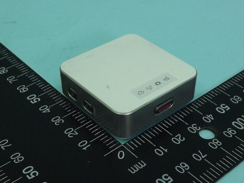
Click to zoom
Application Details
- Equipment Class
- DTS - Digital Transmission System
- Date of Grant
- Aug 21, 2013
- Application Purpose
- Original Equipment
- Date of Application
- Aug 20, 2013
- Equipment Note
- APOEYE
- Frequency Range
- 2412.00000000 - 2462.00000000
- Company
- Carry Technology Co., Ltd.
- Country
- Taiwan
Documents & Files
Document Text
Text extracted from the exhibit documents filed with the FCC. Open a document above to read the original.
Users Manual
Wireless Camcorder User Manual | 1| 1 English Names of Parts Clip MountMagnet Mount Tripod Mount Strap Mount Record Button Status Indicator Mic Micro SD Card Slot Micro USB Port Strap Hook Speaker Video Mode Photo Mode Direct Mode Cloud Mode Mode Button Power Button | 2 English Getting Started Charging the Unit • Before initial use, fully charge the camera via power adapter or USB to computer system. • During charging, the status indicator flashes in red. When the camera is fully charged, the indicator turns off. Modes Navigation • Press Power button to turn on the camera. • Press Mode button to switch among Video-Direct Mode, Photo- Direct Mode, and Cloud Mode. Camera Modes Insert micro SD card (sold separately). Video Mode • Press Mode button to select Video Mode. • Press Record button to shoot and press again to stop. Photo Mode • Press Mode button to select Photo Mode. • Press Record button to take pictures. Wireless Modes Before using wireless modes, install below applications: • Mobile app: Download [ApoEye] from Google Play or Apple Store. • PC software: Install [PC APP] from the camera (Windows)(page 6). Direct Mode Connecting camera to mobile or PC directly for remote controlling, live viewing, album managing, and camera setup. Cloud Mode Connecting camera to cloud server via access point (AP) or mobile hotspot for internet video or live monitoring. | 3| 2 English Getting Started Direct Mode (Local) For initial use, install [ApoEye] app on mobile. Each camera has a unique Camera ID. ( U2-xxxxxxxx) Password is not required for the initial use, however, it is advised to go to [Setup] in app to setup password after connected. • Set camera to Direct Mode and wait until indicator turns steady green. • On mobile, activate WiFi. • Run [ApoEye]. • Press camera bar to start. Connect to Camera • Set camera to Direct Mode . • On mobile, go to [Settings] [Wi-Fi]Choose a camera. 3G connection will switch to WiFi within 1 min. • Run [ApoEye]. • Press camera bar to start. For iOS user: For Android user: Direct Mode (Intranet) Mobile / PC Take Photo (SD card required) (SD card required) Loop Recording • Record and archive in 3 min interval Quad View Zoom In Zoom out Shoot Video Invert Image Two Way Voice • Tap to enable Quad View (up to four cameras). • Tap a live view window to return to single view. • Tap to talk to the camera from mobile; tap again to allow the camera to talk back to mobile. Android: iOS: Note:1. Move the camera further away from mobile when echo occurs. 2. Mobiles with low CPU clock speed may not have audio during streaming. Ver.1.0 U2-00000001 Available U2-00000002 Available U2-00000003 Available CURRENT_AP Connected U2-00000001 Available U2-00000002 Available View View Album Album View View Setup Setup | 4 English Cloud Mode (Internet) AP Cloud Server Cloud AP AP Mobile Hotspot Mobile / PC USTREAM 3G/4G A live broadcasting social media. USTREAM Recommended Cloud Server for Access: Cloud Mode (Internet) Cloud Mode (Internet) Before using Cloud Mode, setting up cloud AP and cloud server on camera are required. Step 1: Setup Cloud AP in Direct Mode On mobile, go to app [Setup][Cloud Settings][Cloud AP]. Select a WiFi network from [AP List]; enter network password when prompted. If no preferred AP is found, press [Other...] from [AP List] Enter network name and password. Note: Mobile hotspot can be set as cloud AP. Step 2: Setup Cloud Server in Direct Mode • New user, press then enter email/username/password/ confirm for auto-registration. Returning user, enter username/ password only. • Press [Save to Camera]. | 5| 4 English Cloud Mode (Internet) Cloud Mode (Internet) Step 3: Connect Camera to Cloud Server Options to connect to cloud server: 1. On mobile, press [Camera to Cloud] in [Setup] page. 2. On camera, set to Cloud Mode . While connecting, the status indicator flashes rapidly in orange. Once connected, the status indicator flashes in green. If connection fails, the status indicator flashes in red and alerts in different beeping frequencies. Or go into [ApoEye] to view the error message. Note: 1. Cloud service may change depending on their policy. 2. In some areas, mobile may not activate hotspot where there is no 3G/4G. 3. Experiencing delays while viewing live video may be due to high internet traffic. AlertCause/Solution One time Cannot connect to cloud AP or invalid network password. Camera not inside WiFi area or weak signal. Check AP settings or move camera closer to cloud AP. Two times No internet or the cloud server is not accessible. Cannot log in cloud server via internet. Cloud service may be blocked by firewall. Three times Cloud server username or password is incorrect. Refer to in [Setup] for instructions. Username already taken. Create new account in [ApoEye]. Step 4: View Live Videos on Cloud Server Options to view live videos: 1. Use mobile app: USTREAM is available in Google Play or Apple Store. 2. Visit website: http://www.ustream.tv Then search for username and select "username's show" to watch live video through camera. | 6 English PC Applications To use [ApoEye] features on PC, install [PC APP] first. The [PC APP] has similar features and interface to [ApoEye] for easy user experience. Installing [PC APP] from Camera • Connect the camera to PC via a USB cable. • [PC APP] AutoRun/AutoPlay activates. • If AutoRun/AutoPlay is not starting: Go to [My computer] and search [PC APP] for installation. • Once installed, unplug the camera from PC then run [PC APP]. [PC APP] Features • Press [View HD] or double-click the viewing window to maximize it into full screen. Double-click again to return to the [PC APP] interface. • To save videos or photos to PC: Go to [Album] Select videos or photos Press [Save to PC]. Mass Storage and Webcam Modes While camera is plugged in to PC, press Mode button on camera to switch between Mass Storage Mode (default) and Webcam Mode. The status indicator shows steady red in Mass Storage Mode and steady green in Webcam Mode ( I…
Text truncated - open the document above for the full version.
External Photos
FCC Test Report Report No. : EP2D1005-0 4 SPORTON International Inc. PAGE NUMBER : B1 OF B27 TEL : 886-3-327-3456 ISSUED DATE : Aug. 13, 2013 FAX : 886-3-327-0973 APPENDIX B. Photographs of EUT FCC Test Report Report No. : EP2D1005-0 4 SPORTON International Inc. PAGE NUMBER : B2 OF B27 TEL : 886-3-327-3456 ISSUED DATE : Aug. 13, 2013 FAX : 886-3-327-0973 FCC Test Report Report No. : EP2D1005-0 4 SPORTON International Inc. PAGE NUMBER : B3 OF B27 TEL : 886-3-327-3456 ISSUED DATE : Aug. 13, 2013 FAX : 886-3-327-0973 FCC Test Report Report No. : EP2D1005-0 4 SPORTON International Inc. PAGE NUMBER : B4 OF B27 TEL : 886-3-327-3456 ISSUED DATE : Aug. 13, 2013 FAX : 886-3-327-0973 FCC Test Report Report No. : EP2D1005-0 4 SPORTON International Inc. PAGE NUMBER : B5 OF B27 TEL : 886-3-327-3456 ISSUED DATE : Aug. 13, 2013 FAX : 886-3-327-0973 FCC Test Report Report No. : EP2D1005-0 4 SPORTON International Inc. PAGE NUMBER : B6 OF B27 TEL : 886-3-327-3456 ISSUED DATE : Aug. 13, 2013 FAX : 886-3-327-0973
ID Label/Location Info
EUT Back Label Location
Internal Photos
FCC Test Report Report No. : EP2D1005-0 4 SPORTON International Inc. PAGE NUMBER : B7 OF B27 TEL : 886-3-327-3456 ISSUED DATE : Aug. 13, 2013 FAX : 886-3-327-0973 FCC Test Report Report No. : EP2D1005-0 4 SPORTON International Inc. PAGE NUMBER : B8 OF B27 TEL : 886-3-327-3456 ISSUED DATE : Aug. 13, 2013 FAX : 886-3-327-0973 FCC Test Report Report No. : EP2D1005-0 4 SPORTON International Inc. PAGE NUMBER : B9 OF B27 TEL : 886-3-327-3456 ISSUED DATE : Aug. 13, 2013 FAX : 886-3-327-0973 FCC Test Report Report No. : EP2D1005-0 4 SPORTON International Inc. PAGE NUMBER : B10 OF B27 TEL : 886-3-327-3456 ISSUED DATE : Aug. 13, 2013 FAX : 886-3-327-0973 FCC Test Report Report No. : EP2D1005-0 4 SPORTON International Inc. PAGE NUMBER : B11 OF B27 TEL : 886-3-327-3456 ISSUED DATE : Aug. 13, 2013 FAX : 886-3-327-0973 WLAN Module FCC Test Report Report No. : EP2D1005-0 4 SPORTON International Inc. PAGE NUMBER : B12 OF B27 TEL : 886-3-327-3456 ISSUED DATE : Aug. 13, 2013 FAX : 886-3-327-0973 FCC Test Report Report No. : EP2D1005-0 4 SPORTON International Inc. PAGE NUMBER : B13 OF B27 TEL : 886-3-327-3456 ISSUED DATE : Aug. 13, 2013 FAX : 886-3-327-0973 FCC Test Report Report No. : EP2D1005-0 4 SPORTON International Inc. PAGE NUMBER : B14 OF B27 TEL : 886-3-327-3456 ISSUED DATE : Aug. 13, 2013 FAX : 886-3-327-0973 PIFA Antenna FCC Test Report Report No. : EP2D1005-0 4 SPORTON International Inc. PAGE NUMBER : B15 OF B27 TEL : 886-3-327-3456 ISSUED DATE : Aug. 13, 2013 FAX : 886-3-327-0973 FCC Test Report Report No. : EP2D1005-0 4 SPORTON International Inc. PAGE NUMBER : B16 OF B27 TEL : 886-3-327-3456 ISSUED DATE : Aug. 13, 2013 FAX : 886-3-327-0973 FCC Test Report Report No. : EP2D1005-0 4 SPORTON International Inc. PAGE NUMBER : B17 OF B27 TEL : 886-3-327-3456 ISSUED DATE : Aug. 13, 2013 FAX : 886-3-327-0973 FCC Test Report Report No. : EP2D1005-0 4 SPORTON International Inc. PAGE NUMBER : B18 OF B27 TEL : 886-3-327-3456 ISSUED DATE : Aug. 13, 2013 FAX : 886-3-327-0973 FCC Test Report Report No. : EP2D1005-0 4 SPORTON International Inc. PAGE NUMBER : B19 OF B27 TEL : 886-3-327-3456 ISSUED DATE : Aug. 13, 2013 FAX : 886-3-327-0973 FCC Test Report Report No. : EP2D1005-0 4 SPORTON International Inc. PAGE NUMBER : B20 OF B27 TEL : 886-3-327-3456 ISSUED DATE : Aug. 13, 2013 FAX : 886-3-327-0973 FCC Test Report Report No. : EP2D1005-0 4 SPORTON International Inc. PAGE NUMBER : B21 OF B27 TEL : 886-3-327-3456 ISSUED DATE : Aug. 13, 2013 FAX : 886-3-327-0973 FCC Test Report Report No. : EP2D1005-0 4 SPORTON International Inc. PAGE NUMBER : B22 OF B27 TEL : 886-3-327-3456 ISSUED DATE : Aug. 13, 2013 FAX : 886-3-327-0973 FCC Test Report Report No. : EP2D1005-0 4 SPORTON International Inc. PAGE NUMBER : B23 OF B27 TEL : 886-3-327-3456 ISSUED DATE : Aug. 13, 2013 FAX : 886-3-327-0973 FCC Test Report Report No. : EP2D1005-0 4 SPORTON International Inc. PAGE NUMBER : B24 OF B27 TEL : 886-3-327-3456 ISSUED DATE : Aug. 13, 2013 FAX : 886-3-327-0973 FCC Test Report Report No. : EP2D1005-0 4 SPORTON International Inc. PAGE NUMBER : B25 OF B27 TEL : 886-3-327-3456 ISSUED DATE : Aug. 13, 2013 FAX : 886-3-327-0973 FCC Test Report Report No. : EP2D1005-0 4 SPORTON International Inc. PAGE NUMBER : B26 OF B27 TEL : 886-3-327-3456 ISSUED DATE : Aug. 13, 2013 FAX : 886-3-327-0973 FCC Test Report Report No. : EP2D1005-0 4 SPORTON International Inc. PAGE NUMBER : B27 OF B27 TEL : 886-3-327-3456 ISSUED DATE : Aug. 13, 2013 FAX : 886-3-327-0973
RF Exposure Info
SPORTON INTERNATIONAL INC. Page Number : 1 of 30 TEL : 886-3-327-3456 Report Issued Date : Aug. 13, 2013 FAX : 886-3-328-4978 Report Version : Rev. 01 FCC ID : JY8WIE001 FCC SAR Test Report Report No. : FA2D1005-04 FCC SAR Test Report APPLICANT : Carry Technology Co., Ltd. EQUIPMENT : ApoEye BRAND NAME : Apotop MODEL NAME : DW31 FCC ID : JY8WIE001 STANDARD : FCC 47 CFR Part 2 (2.1093) ANSI/IEEE C95.1-1992 IEEE 1528-2003 The product was completely tested on Jan. 25, 2013. We, SPORTON INTERNATIONAL INC., would like to declare that the tested sample has been evaluated in accordance with the procedures and shown the compliance with the applicable technical standards. The test results in this report apply exclusively to the tested model / sample. Without written approval of SPORTON INTERNATIONAL INC., the test report shall not be reproduced except in full. SPORTON INTERNATIONAL INC. No. 52, Hwa Ya 1 st Rd., Hwa Ya Technology Park, Kwei-Shan Hsiang, Tao Yuan Hsien, Taiwan, R.O.C. Approved by: Jones Tsai / Manager Reviewed by: Eric Huang / Deputy Manager SPORTON INTERNATIONAL INC. Page Number : 2 of 30 TEL : 886-3-327-3456 Report Issued Date : Aug. 13, 2013 FAX : 886-3-328-4978 Report Version : Rev. 01 FCC ID : JY8WIE001 FCC SAR Test Report Report No. : FA2D1005-04 Table of Contents 1. Statement of Compliance ............................................................................................................................................. 4 2. Administration Data ...................................................................................................................................................... 4 2.1 Testing Laboratory .................................................................................................................................................. 4 2.2 Applicant ................................................................................................................................................................ 4 2.3 Manufacturer .......................................................................................................................................................... 4 2.4 Application Details .................................................................................................................................................. 4 3. General Information ...................................................................................................................................................... 5 3.1 Description of Equipment Under Test (EUT) .......................................................................................................... 5 3.2 Maximum RF output power among production units .............................................................................................. 5 3.3 Applied Standards .................................................................................................................................................. 6 3.4 Device Category and SAR Limits ........................................................................................................................... 6 3.5 Test Conditions ....................................................................................................................................................... 6 4. Specific Absorption Rate (SAR) ................................................................................................................................... 7 4.1 Introduction ............................................................................................................................................................ 7 4.2 SAR Definition ........................................................................................................................................................ 7 5. SAR Measurement System ........................................................................................................................................... 8 5.1 E-Field Probe ......................................................................................................................................................... 9 5.2 Data Acquisition Electronics (DAE) .......................................................................................................................10 5.3 Robot ....................................................................................................................................................................10 5.4 Measurement Server .............................................................................................................................................10 5.5 Phantom ................................................................................................................................................................ 11 5.6 Device Holder........................................................................................................................................................12 5.7 Data Storage and Evaluation ................................................................................................................................13 5.8 Test Equipment List ...............................................................................................................................................15 6. Tissue Simulating Liquids ...........................................................................................................................................16 7. SAR Measurement Evaluation ....................................................................................................................................18 7.1 Purpose of System Performance check ................................................................................................................18 7.2 System Setup .........................................................................................................................…
Text truncated - open the document above for the full version.
RF Exposure Info
Test Laboratory: Sporton International Inc. SAR/HAC Testing Lab Date: 2013/1/25 System Check_Body_2450MHz_130125 DUT: D2450V2-SN:736 Communication System: CW; Frequency: 2450 MHz;Duty Cycle: 1:1 Medium: MSL_2450_130125 Medium parameters used: f = 2450 MHz; σ = 2.015 mho/m; ε r = 53.957; ρ = 1000 kg/m 3 Ambient Temperature:22.5 °C; Liquid Temperature:21.5 °C DASY5 Configuration: - Probe: EX3DV4 - SN3578; ConvF(6.43, 6.43, 6.43); Calibrated: 2012/6/21; - Sensor-Surface: 2mm (Mechanical Surface Detection) - Electronics: DAE4 Sn910; Calibrated: 2012/12/5 - Phantom: ELI v4.0; Type: QDOVA001BB; Serial: 1173 - Measurement SW: DASY52, Version 52.8 (1); SEMCAD X Version 14.6.5 (6469) Configuration/Pin=250mW/Area Scan (61x61x1): Measurement grid: dx=12mm, dy=12mm Maximum value of SAR (interpolated) = 20.7 mW/g Configuration/Pin=250mW/Zoom Scan (7x7x7)/Cube 0: Measurement grid: dx=5mm, dy=5mm, dz=5m m Reference Value = 98.760 V/m; Power Drift = 0.01 dB Peak SAR (extrapolated) = 28.279 mW/g SAR(1 g) = 12.2 mW/g; SAR(10 g) = 5.34 mW/g Maximum value of SAR (measured) = 19.1 mW/g 0 dB = 19.1 mW/g = 25.62 dB mW/g
RF Exposure Info
Test Laboratory: Sporton International Inc. SAR/HAC Testing Lab Date: 2013/1/25 #01_WLAN 2.4G_802.11b_Front_0cm_Ch6 DUT: 2D1005-04 Communication System: 802.11b ; Frequency: 2437 MHz;Duty Cycle: 1:1 Medium: MSL_2450_130125 Medium parameters used: f = 2437 MHz; σ = 1.996 mho/m; ε r = 53.979; ρ = 1000 kg/m 3 Ambient Temperature:22.5 °C; Liquid Temperature:21.5 °C DASY5 Configuration: - Probe: EX3DV4 - SN3578; ConvF(6.43, 6.43, 6.43); Calibrated: 2012/6/21; - Sensor-Surface: 2mm (Mechanical Surface Detection) - Electronics: DAE4 Sn910; Calibrated: 2012/12/5 - Phantom: ELI v4.0; Type: QDOVA001BB; Serial: 1173 - Measurement SW: DASY52, Version 52.8 (1); SEMCAD X Version 14.6.5 (6469) Configuration/Ch6/Area Scan (61x71x1): Measurement grid: dx=12mm, dy=12mm Maximum value of SAR (interpolated) = 1.49 mW/g Configuration/Ch6/Zoom Scan (7x7x7)/Cube 0: Measurement grid: dx=5mm, dy=5mm, dz=5mm Reference Value = 21.991 V/m; Power Drift = 0.04 dB Peak SAR (extrapolated) = 1.666 mW/g SAR(1 g) = 0.969 mW/g; SAR(10 g) = 0.574 mW/g Maximum value of SAR (measured) = 1.30 mW/g Configuration/Ch6/Zoom Scan (7x7x7)/Cube 1: Measurement grid: dx=5mm, dy=5mm, dz=5mm Reference Value = 21.991 V/m; Power Drift = 0.04 dB Peak SAR (extrapolated) = 1.652 mW/g SAR(1 g) = 0.885 mW/g; SAR(10 g) = 0.495 mW/g Maximum value of SAR (measured) = 1.24 mW/g 0 dB = 1.24 mW/g = 1.87 dB mW/g Test Laboratory: Sporton International Inc. SAR/HAC Testing Lab Date: 2013/1/25 #14_WLAN 2.4G_802.11b_Front_0cm_Ch1 DUT: 2D1005-04 Communication System: 802.11b ; Frequency: 2412 MHz;Duty Cycle: 1:1 Medium: MSL_2450_130125 Medium parameters used: f = 2412 MHz; σ = 1.959 mho/m; ε r = 54.047; ρ = 1000 kg/m 3 Ambient Temperature:22.5 °C; Liquid Temperature:21.5 °C DASY5 Configuration: - Probe: EX3DV4 - SN3578; ConvF(6.43, 6.43, 6.43); Calibrated: 2012/6/21; - Sensor-Surface: 2mm (Mechanical Surface Detection) - Electronics: DAE4 Sn910; Calibrated: 2012/12/5 - Phantom: ELI v4.0; Type: QDOVA001BB; Serial: 1173 - Measurement SW: DASY52, Version 52.8 (1); SEMCAD X Version 14.6.5 (6469) Configuration/Ch1/Area Scan (61x71x1): Measurement grid: dx=12mm, dy=12mm Maximum value of SAR (interpolated) = 2.15 mW/g Configuration/Ch1/Zoom Scan (7x7x7)/Cube 0: Measurement grid: dx=5mm, dy=5mm, dz=5m m Reference Value = 27.358 V/m; Power Drift = 0.01 dB Peak SAR (extrapolated) = 1.871 mW/g SAR(1 g) = 1.07 mW/g; SAR(10 g) = 0.624 mW/g Maximum value of SAR (measured) = 1.45 mW/g Configuration/Ch1/Zoom Scan (7x7x7)/Cube 1: Measurement grid: dx=5mm, dy=5mm, dz=5mm Reference Value = 27.358 V/m; Power Drift = 0.01 dB Peak SAR (extrapolated) = 2.428 mW/g SAR(1 g) = 0.983 mW/g; SAR(10 g) = 0.543 mW/g Maximum value of SAR (measured) = 1.48 mW/g 0 dB = 1.48 mW/g = 3.41 dB mW/g Test Laboratory: Sporton International Inc. SAR/HAC Testing Lab Date: 2013/1/25 #16_WLAN 2.4G_802.11b_Front_0cm_Ch11 DUT: 2D1005-04 Communication System: 802.11b ; Frequency: 2462 MHz;Duty Cycle: 1:1 Medium: MSL_2450_130125 Medium parameters used: f = 2462 MHz; σ = 2.032 mho/m; ε r = 53.942; ρ = 1000 kg/m 3 Ambient Temperature:22.5 °C; Liquid Temperature:21.5 °C DASY5 Configuration: - Probe: EX3DV4 - SN3578; ConvF(6.43, 6.43, 6.43); Calibrated: 2012/6/21; - Sensor-Surface: 2mm (Mechanical Surface Detection) - Electronics: DAE4 Sn910; Calibrated: 2012/12/5 - Phantom: ELI v4.0; Type: QDOVA001BB; Serial: 1173 - Measurement SW: DASY52, Version 52.8 (1); SEMCAD X Version 14.6.5 (6469) Configuration/Ch11/Area Scan (61x71x1): Measurement grid: dx=12mm, dy=12mm Maximum value of SAR (interpolated) = 1.50 mW/g Configuration/Ch11/Zoom Scan (7x7x7)/Cube 0: Measurement grid: dx=5mm, dy=5mm, dz=5m m Reference Value = 22.069 V/m; Power Drift = 0.08 dB Peak SAR (extrapolated) = 1.585 mW/g SAR(1 g) = 0.726 mW/g; SAR(10 g) = 0.420 mW/g Maximum value of SAR (measured) = 1.06 mW/g Configuration/Ch11/Zoom Scan (7x7x7)/Cube 1: Measurement grid: dx=5mm, dy=5mm, dz=5mm Reference Value = 22.069 V/m; Power Drift = 0.08 dB Peak SAR (extrapolated) = 1.653 mW/g SAR(1 g) = 0.717 mW/g; SAR(10 g) = 0.388 mW/g Maximum value of SAR (measured) = 1.08 mW/g 0 dB = 1.08 mW/g = 0.67 dB mW/g Test Laboratory: Sporton International Inc. SAR/HAC Testing Lab Date: 2013/1/25 #02_WLAN 2.4G_802.11b_Back_0cm_Ch6 DUT: 2D1005-04 Communication System: 802.11b ; Frequency: 2437 MHz;Duty Cycle: 1:1 Medium: MSL_2450_130125 Medium parameters used: f = 2437 MHz; σ = 1.996 mho/m; ε r = 53.979; ρ = 1000 kg/m 3 Ambient Temperature:22.5 °C; Liquid Temperature:21.5 °C DASY5 Configuration: - Probe: EX3DV4 - SN3578; ConvF(6.43, 6.43, 6.43); Calibrated: 2012/6/21; - Sensor-Surface: 2mm (Mechanical Surface Detection) - Electronics: DAE4 Sn910; Calibrated: 2012/12/5 - Phantom: ELI v4.0; Type: QDOVA001BB; Serial: 1173 - Measurement SW: DASY52, Version 52.8 (1); SEMCAD X Version 14.6.5 (6469) Configuration/Ch6/Area Scan (61x71x1): Measurement grid: dx=12mm, dy=12mm Maximum value of SAR (interpolated) = 1.50 mW/g Configuration/Ch6/Zoom Scan (7x7x7)/Cube 0: Measurement grid: dx=5mm, dy=5mm, dz=5m m Reference Value = 24.796 V/m; Power Drift = 0.08 dB Peak SAR (extrapolated) = 2.173 mW/g SAR(1 g) = 0.991 mW/g; SAR(10 g) = 0.559 mW/g Maximum value of SAR (measured) = 1.49 mW/g 0 dB = 1.49 mW/g = 3.46 dB mW/g Test Laboratory: Sporton International Inc. SAR/HAC Testing Lab Date: 2013/1/25 #15_WLAN 2.4G_802.11b_Back_0cm_Ch1 DUT: 2D1005-04 Communication System: 802.11b ; Frequency: 2412 MHz;Duty Cycle: 1:1 Medium: MSL_2450_130125 Medium parameters used: f = 2412 MHz; σ = 1.959 mho/m; ε r = 54.047; ρ = 1000 kg/m 3 Ambient Temperature:22.5 °C; Liquid Temperature:21.5 °C DASY5 Configuration: - Probe: EX3DV4 - SN3578; ConvF(6.43, 6.43, 6.43); Calibrated: 2012/6/21; - Sensor-Surface: 2mm (Mechanical Surface Detection) - Electronics: DAE4 Sn910; Calibrated: 2012/12/5 - Phantom: ELI v4.0; Type: QDOVA001BB; Serial: 1173 - Measurement SW: DASY52, Version 52.8 (1); SEMCAD X Version 14.6.5 (6469) Configuration/Ch1/Area Scan (61x71x1): Measurement grid: dx=12mm, dy=12mm Maximum value of S…
Text truncated - open the document above for the full version.
RF Exposure Info
SPORTON INTERNATIONAL INC. TEL : 886-3-327-3456 FAX : 886-3-328-4978 D2450V2, serial no. 736 Extended Dipole Calibrations Referring to KDB 865664 D01v01r01, if dipoles are verified in return loss (<-20dB, within 20% of prior calibration), and in impedance (within 5 ohm of prior calibration), the annual calibration is not necessary and the calibration interval can be extended. <Justification Procedure of Extended Dipole Calibration> 1. Setup a Network Analyzer (Agilent N5230A) and set the start frequency and stop frequency to Network Analyzer according to the dipole frequency, at least +/- 200MHz around the calibration point. 2. Using calibration kit to perform Network Analyzer Open, Short and Load calibration. 3. Connect the dipole with the calibrated Network Analyzer. 4. Place the dipole underneath the phantom which is filled with head-simulating or body-simulating liquid. 5. Set the Network Analyzer frequency by the dipole calibration frequency. Monitor the return-loss and impedance results with Log Magnitude format and Smith Chart, respectively. 6. Record the result and compare with the prior calibration. Please check the Appendix C for detail records. <Justification of the extended calibration> D2450V2 – serial no. 736 2450 Head 2450 Body Date of Measurement Return-Loss (dB) Delta (%) Real Impedance (ohm) Delta (ohm) Imaginary Impedance (ohm) Delta (ohm) Return-Loss (dB) Delta (%) Real Impedance (ohm) Delta (ohm) Imaginary Impedance (ohm) Delta (ohm) 7.25.2011 -27.042 54.398 1.4805 -30.696 50.812 2.8262 7.25.2012 -27.950 -3.365 52.541 1.857 0.77343 0.707 -31.781 -3.535 50.572 0.24 1.5953 1.2309 The return loss is < -20dB, within 20% of prior calibration; the impedance is within 5 ohm of prior calibration. Therefore the verification result should support extended calibration. SPORTON INTERNATIONAL INC. TEL : 886-3-327-3456 FAX : 886-3-328-4978 <Dipole Verification Data> - D2450 V2, serial no. 736 (Date of Measurement : 7.25.2012) 2450 MHz - Head SPORTON INTERNATIONAL INC. TEL : 886-3-327-3456 FAX : 886-3-328-4978 2450 MHz – Body
Test Report
FCC Test Report Report No. : FR2D1005-04 SPORTON INTERNATIONAL INC. Page No. : 1 of 49 TEL : 886-3-327-3456 Report Version : Rev. 01 FAX : 886-3-327-0973 FCC Test Report Equipment : ApoEye Brand Name : Apotop Model No. : DW31 FCC ID : JY8WIE001 Standard : 47 CFR FCC Part 15.247 Operating Band : 2400 MHz – 2483.5 MHz Equipment Class : DTS Applicant Manufacturer : Carry Technology Co., Ltd. 4F, No.119, JianKang Road, Jhonghe Dist, New Taipei City 23585, Taiwan The product sample received on Jan. 14, 2013 and completely tested on Jun. 01, 2013. We, SPORTON, would like to declare that the tested sample has been evaluated in accordance with the procedures given in ANSI C63.10-2009 and shown compliance with the applicable technical standards. The test results in this report apply exclusively to the tested model / sample. Without written approval of SPORTON INTERNATIONAL INC., the test report shall not be reproduced except in full. Reviewed by: Wayne Hsu / Assistant Manager FCC Test Report Report No. : FR2D1005-04 SPORTON INTERNATIONAL INC. Page No. : 2 of 49 TEL : 886-3-327-3456 Report Version : Rev. 01 FAX : 886-3-327-0973 Table of Contents 1 GENERAL DESCRIPTION ............................................................................................................... 5 1.1 Information ........................................................................................................................................ 5 1.2 Accessories and Support Equipment ................................................................................................. 7 1.3 Testing Applied Standards ................................................................................................................ 7 1.4 Testing Location Information ............................................................................................................. 8 1.5 Measurement Uncertainty ................................................................................................................. 9 2 TEST CONFIGURATION OF EUT .................................................................................................. 10 2.1 The Worst Case Modulation Configuration ...................................................................................... 10 2.2 Test Channel Frequencies Configuration ......................................................................................... 10 2.3 The Worst Case Power Setting Parameter ...................................................................................... 10 2.4 The Worst Case Measurement Configuration .................................................................................. 11 2.5 Test Setup Diagram ........................................................................................................................ 12 3 TRANSMITTER TEST RESULT ..................................................................................................... 14 3.1 AC Power-line Conducted Emissions .............................................................................................. 14 3.2 6dB Bandwidth ................................................................................................................................ 17 3.3 RF Output Power ............................................................................................................................ 19 3.4 Power Spectral Density ................................................................................................................... 24 3.5 Transmitter Radiated Bandedge Emissions ..................................................................................... 26 3.6 Transmitter Radiated Unwanted Emissions ..................................................................................... 30 4 TEST EQUIPMENT AND CALIBRATION DATA ............................................................................. 47 APPENDIX A. TEST PHOTOS APPENDIX B. PHOTOGRAPHS OF EUT FCC Test Report Report No. : FR2D1005-04 SPORTON INTERNATIONAL INC. Page No. : 3 of 49 TEL : 886-3-327-3456 Report Version : Rev. 01 FAX : 886-3-327-0973 Summary of Test Result Conformance Test Specifications Report Clause Ref. Std. Clause Description Measured Limit Result 1.1.2 15.203 Antenna Requirement Antenna connector mechanism complied …
Text truncated - open the document above for the full version.
Contact Information
Applicant
Edward Lee(Senior Manager)
Test Firm
Sporton International Inc.Alex Chen
Technical Specifications
| # | Rule Parts | Frequency Range | Power Output |
|---|---|---|---|
| 1 | 15C | 2.41 GHz - 2.46 GHz | 302.70 mW |
Other Applications from Carry Technology Co., Ltd.
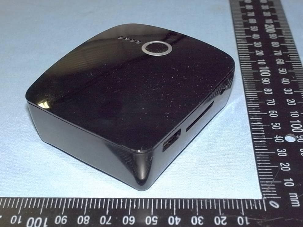
JY8-WIR004
Dec 29, 2013Wireless Reader (DW23, DW28)
Equipment Class
DTS - Digital Transmission System
JY8-WIR003
Dec 16, 2013Wireless Reader
Equipment Class
DTS - Digital Transmission System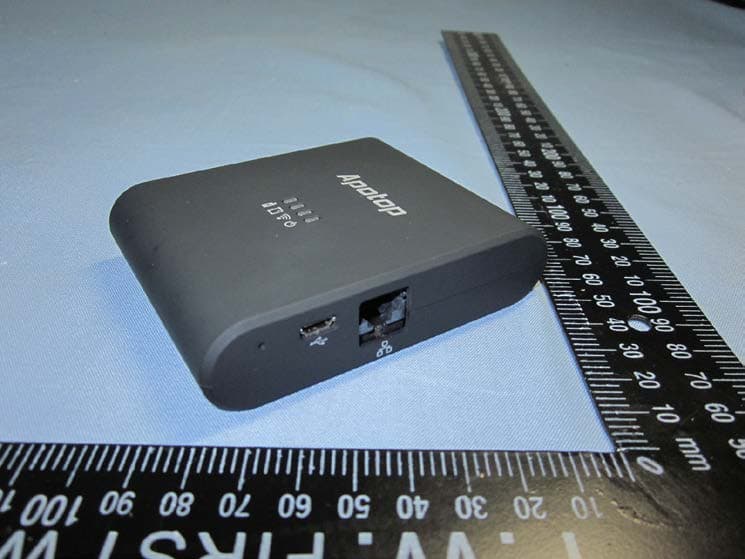
JY8-WIR002
Apr 28, 2013WI-COPY
Equipment Class
DTS - Digital Transmission System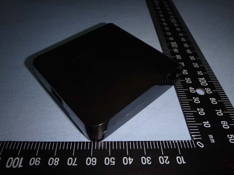
JY8WIR001
Nov 15, 2012WI-READER PRO
Equipment Class
DTS - Digital Transmission System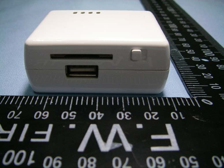
JY8DW09
May 28, 2012WI-READER
Equipment Class
DTS - Digital Transmission System