JZ2OEM300I-Class Encoder
Fargo Electronics Inc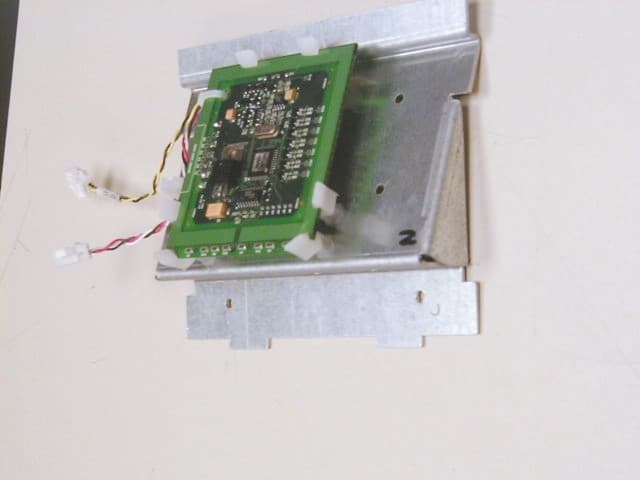
Click to zoom
Application Details
- Equipment Class
- DXX - Part 15 Low Power Communication Device Transmitter
- Date of Grant
- Sep 13, 2005
- Application Purpose
- Original Equipment
- Date of Application
- Sep 13, 2005
- Equipment Note
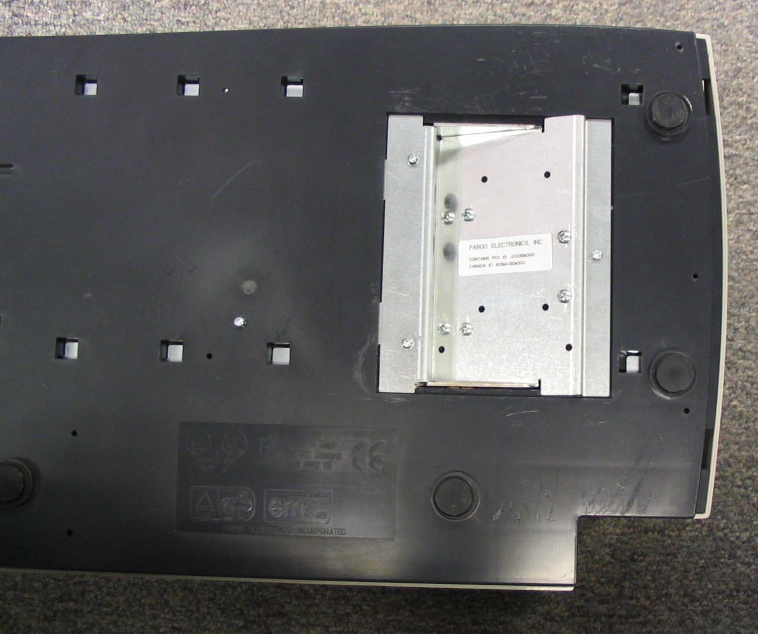
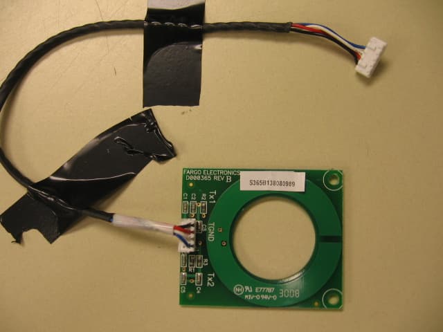
- I-Class Encoder
- Frequency Range
- 13.56000000 - 13.56000000
- Company
- Fargo Electronics Inc
- Country
- United States
Documents & Files
Document Text
Text extracted from the exhibit documents filed with the FCC. Open a document above to read the original.
Cover Letter(s)
www.HIDCorp.com 9292 Jeronimo Road • Irvine, CA 92618-1905 • Phone (949) 598-1600 Fax (949) 598-1680 (Administration) • Fax (949) 598-1690 (Customer Service) • Fax (949) 598-1692 (Manufacturing & Purchasing) An ASSA ABLOY Group company Request that submitted material be withheld from Public Inspection Pursuant to 47 CFR 0.457(d) and 0.459 Product: 3111A iCLASS OEM 300 Module It is requested that the following material be withheld from public inspection: Description of the 3111A iCLASS OEM 300 Module, Circuit Functions, how the device operates, Ground System, and Antenna Block Diagram Schematic These materials are considered HID Corporation Proprietary and Confidential. Revealing the fundamental design for the product to the public, the OEM, and our competition would put us at a competitive disadvantage. We feel we have a product cost/design advantage over our competition with our iCLASS OEM Module family and therefore ask that the above-specified materials be withheld from public and OEM inspection. Frank de Vall Sr. Engineering Manager-Compliance HID Corporation Assa Abloy ITG Research and Development Center 11674 N. Huron Street Denver, CO 80234
Test Report
FCC ID: JZ2OEM300 August 2005 Page 2 of 19 CONTENTS 1.0 GENERAL DESCRIPTION...........................................................................3 1.1 Related Submittals Grants .................................................................................. 3 1.2 Product Description.......................................................................................... 3 1.3 Test Methodology............................................................................................ 3 1.4 Test Facility................................................................................................... 3 2.0 SYSTEM TEST CONFIGURATION...............................................................4 2.1 Justification ................................................................................................... 4 2.2 EUT Setup .................................................................................................... 4 2.3 EUT Exercising Software .................................................................................. 4 2.4 Special Accessories .......................................................................................... 4 2.5 Equipment Modification .................................................................................... 4 2.6 Support Equipment List and Description................................................................. 4 2.7 Test Configuration Block Diagrams ...................................................................... 5 3.0 TEST RESULTS..........................................................................................6 3.1 Field Strength of Radiated Emissions, FCC 15.225(a)(b)(c), 15.209 ............................... 7 3.2 Out of Band Spurious Emissions, FCC 15.225(d), 15.209 ........................................... 8 3.3 Field Strength of Spurious Emissions, FCC 15.205, 15.209 ......................................... 9 3.4 Frequency Tolerance, FCC 15.225(e)...................................................................12 3.5 Bandwidth of Emissions, FCC 15.215 ..................................................................13 3.6 Line Conducted Emissions, FCC 15.207 ...............................................................15 3.6 Test Procedure...............................................................................................17 3.7 Field Strength Calculation .................................................................................18 3.8 Measurement Uncertainty .................................................................................18 4.0 TEST EQUIPMENT................................................................................... 19 FCC ID: JZ2OEM300 August 2005 Page 3 of 19 1.0 GENERAL DESCRIPTION 1.1 Related Submittals Grants This is single application of the I-Class Encoder OEM300 Transmitter for Certification under Part 15 Subpart C. There are no other simultaneous applications . 1.2 Product Description The I-Class Encoder OEM300 Transmitter is operating at 13.56 MHz. The I-Class Encoder OEM300 Transmitter is incorporated in X001300 Printer and X001500 Printer (as an optional) manufactured by Fargo Electronics Inc. The Transmitters are identical for both devices. The intended use of the I-Class Encoder OEM300 Transmitter is to generate and transmit a RF signal from the Antenna to the I-Class ID Card; the same antenna is used to receive modified by the I-Class ID Card signal (inductive coupling). The I-Class Encoder OEM300 Transmitter is powered at 12VDC from the host device (X001300 Printer and X001500 Printer). For purpose of testing the Transmitter was powered at 120VAC, 60 Hz through the AC/DC Power Adapter. The I-Class Encoder OEM300 Transmitter antenna is an integral antenna located on the same with the transmitter PCB. Sample Submitted: August 4, 2005 Test Work Started: August 4, 2005 Test Work Completed: August 29, 2005 1.3 Test Methodology Emission measurements were performed according to the procedures in ANSI C63.4-2003. All field strength radiated emissions measurements were performed in the semi-anechoic chamber, and for each scan, the procedure for maximizing emissions in were followed. All field strength radiated tests were performed at an antenna to EUT distance of 3 meters, unless stated otherwise in the "Justification Section" of this Application. 1.4 Test Facility The test site facility used to collect the radiated and conducted measurement data is located at 7250 Hudson Blvd., Suite 100, Oakdale, Minnesota. This test facility has been fully described in a report dated on March 2003 submitted to FCC. Please reference the site registration number: 90706, dated April 18, 2003. FCC ID: JZ2OEM300 August 2005 Page 4 of 19 2.0 SYSTEM TEST CONFIGURATION 2.1 Justification To demonstrate the I-Class Encoder OEM300 Transmitter compliance the transmitter was tested without enclosure on the metal plate, which is used for transmitter mounting in the host device. 2.2 EUT Setup For simplicity of testing, the transmitter was set to transmit continuously. 2.3 EUT Exercising Software The transmitter was exercised with I-Class Encoder OEM300 Firmware. 2.4 Special Accessories There are no special accessories necessary for compliance of these products. 2.5 Equipment Modification No modifications were installed during the testing. 2.6 Support Equipment List and Description GlobTek 100-240VAC/50-60Hz to 12VDC Power Adapter iClass 2K ID Card FCC ID: JZ2OEM300 August 2005 Page 5 of 19 2.7 Test Configuration Block Diagrams The EUT was setup as tabletop equipment. Measurements below 30MHz were performed at 10-m measurement distance with Loop Antenna. Measurements from 30MHz to 1GHz were performed at 3-m measurement distance with Bicono-Log Antenna. The EUT was powered at 120VAC/60Hz through the Power Adapter. Field Strength Measurements FCC ID: JZ2OEM300 August 2005 Page 6 of 19 3.0 TEST RESULTS Data is included of the worst-case configuration (the configuration which …
Text truncated - open the document above for the full version.
Contact Information
Applicant
Gary M Klinefelter(VP, Technology Development)
Technical Contact
Fargo ElectronicsLeon Gershenovich
[email protected]952-918-8622
6533 Flying Cloud Drive · Eden Prairie, Minnesota · United States
Non-Technical Contact
Fargo ElectronicsJohn Wilson
[email protected]952-918-8622
Test Firm
Intertek Testing Services NA, Inc.Paul Coghill
Technical Specifications
| # | Rule Parts | Frequency Range | Power Output |
|---|---|---|---|
| 1 | 15C | 13.56 MHz - 13.56 MHz | - |
Other Applications from Fargo Electronics Inc
JZ2X001800
Jan 06, 2010Ribbon RFID Encoder
Equipment Class
DXX - Part 15 Low Power Communication Device Transmitter
JZ2X001700
Feb 21, 2007Ribbon RFID
Equipment Class
DXX - Part 15 Low Power Communication Device Transmitter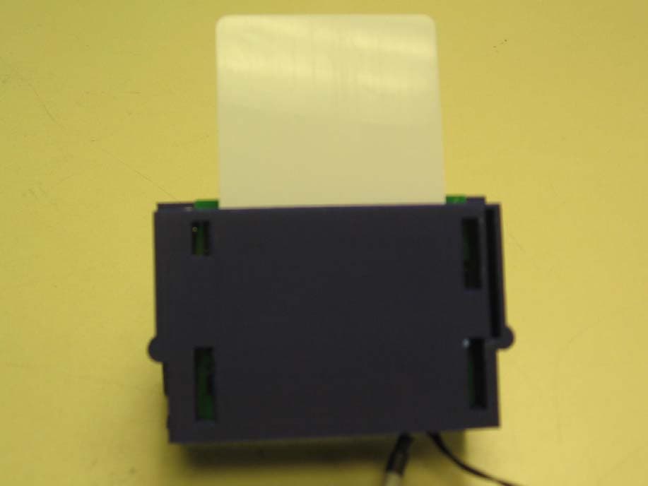
JZ2OMNI5121
Feb 21, 2007Omni Key Reader
Equipment Class
DXX - Part 15 Low Power Communication Device Transmitter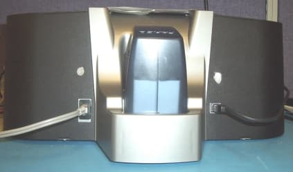
JZ2X001200
Nov 06, 2002CardJet Card Printer
Equipment Class
DXX - Part 15 Low Power Communication Device TransmitterJZ2-5300X
Jul 26, 1995Printer
Equipment Class
JBP - Part 15 Class B Computing Device Peripheral