K3N6000AccessLinkII 2-Way Pager
Glenayre Electronics Inc.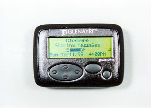
Click to zoom
Application Details
- Equipment Class
- PCT - PCS Licensed Transmitter worn on body
- Date of Grant
- Feb 21, 2000
- Application Purpose
- Original Equipment
- Date of Application
- Nov 09, 1999
- Equipment Note
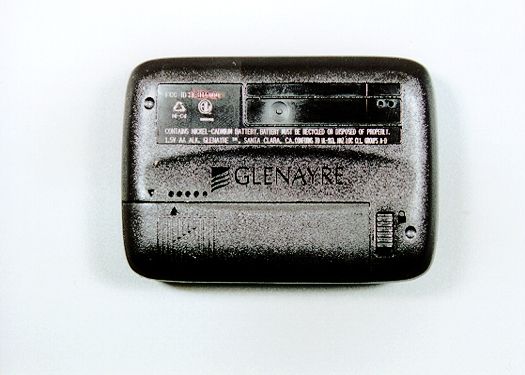
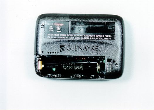
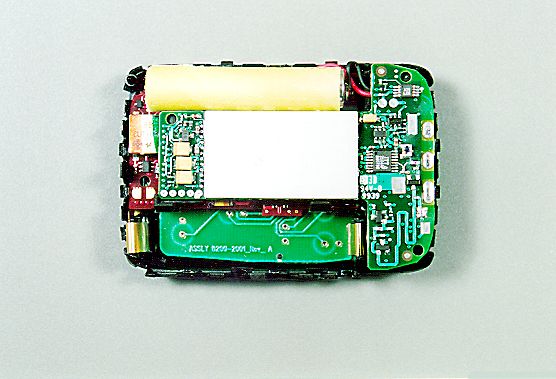
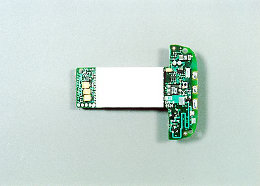
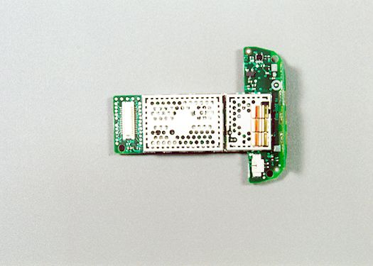
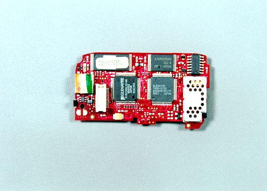
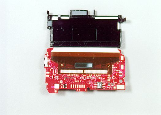
- AccessLinkII 2-Way Pager
- Frequency Range
- 901.00000000 - 902.00000000
- Company
- Glenayre Electronics Inc.
- Country
- United States
Documents & Files
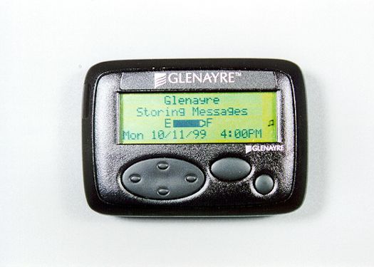
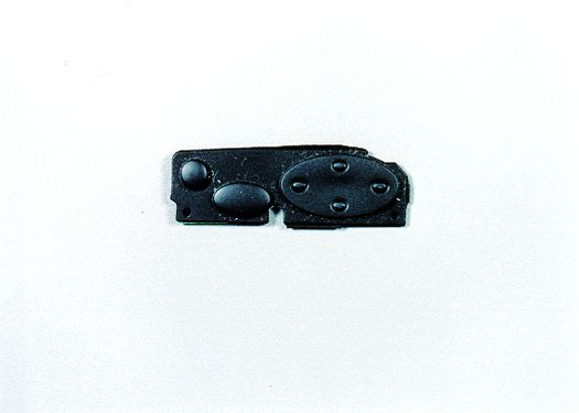

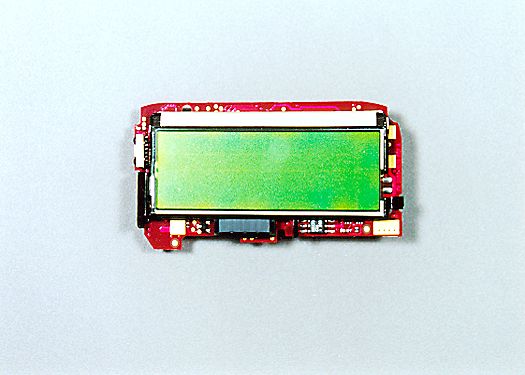
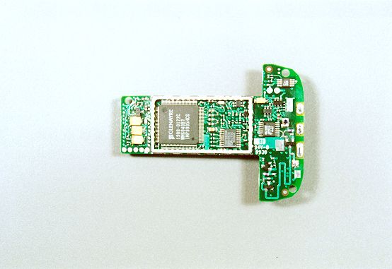
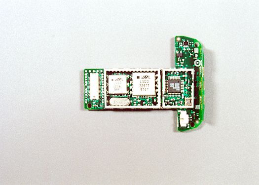
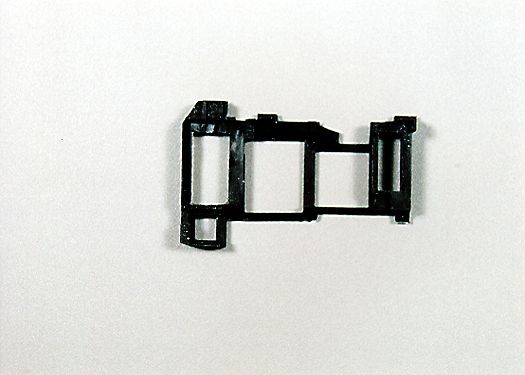
Document Text
Text extracted from the exhibit documents filed with the FCC. Open a document above to read the original.
Users Manual
Using Your AccessLink™ II 2-Way Pager Congratulations on your purchase of the Glenayre AccessLink II advanced messaging, two-way pager! The AccessLink II is simple to use and provides exciting new messaging capabilities. THEVIRTUALKEYBOARDThe AccessLink II has a virtual keyboard to allow you to enter messages and other information. Since this keyboard is created entirely in software, your two-way pager can be as small as a one-way pager. You will use this keyboard often to enter messages or other information. Refer to this page whenever you need a quick reminder about how to use the virtual keyboard. • To "type" letters, use the "Up/Down" and "Left/Right Scroll" buttons to select the appropriate letter and then press the "Enter" button. •When you enter a letter or punctuation character, the cursor returns to the center of the keyboard, which is the space key. To type a space simply press the "Enter" button. • To delete a character, scroll to the bottom of the screen. When the cursor is in the bottom row, press the down scroll button to delete the preceding character. • To change case, scroll to the top row of the keyboard, and select the Up Scroll button. Each press of the Up Scroll button changes the case from lower case, to shift, to caps lock, and back to lower case. • To edit the message, press the "Exit/Backlight" button. The keyboard will disappear, allowing you to scroll through the message with the "Up/Down" and "Left/Right" Scroll buttons. Press the "Enter" button to insert the cursor into the selected position and return the virtual keyboard. •Once you are finished entering a message or other type of information press the "Exit/Backlight" button which takes you to the Edit Screen. Press the "Exit/Backlight" button again to arrive at the Message menu, with options to address, edit, save, or delete the message. • You may exit the editor at any time by pressing the "Exit/Backlight" button until you have backed up to the screen you desire. Any work you have started will be saved in the folder where it was created. Unsent messages will be saved in the TO SEND folder. 2 Vi rtual Keyboard Quick Refere n c e 3 AccessLink II Overv i e w Home Screen “Exit/Backlight” Button: Use to Exit from any screen “Left/Right Scroll” Buttons “Up/Down Scroll” Buttons “Enter” Button Alarm Clock enabled Alarm sounded and still enabled New Messages in Information Services Folders New Messages in RECEIVED Folder RECEIVED message audible alert enabled RECEIVED message vibrate alert enabled Message Icons Unread message Read message Successful send or reply Unsuccessful send or reply Reply Pending Icon Quick Reference Guide Virtual Keyboard Quick Reference . . . . . . . . . . . . . . . . . .2 AccessLink II Overview . . . . . . . . . . . . . . . . . . . . . . . . . . .3 Icon Guide . . . . . . . . . . . . . . . . . . . . . . . . . . . . . . . . . . . . .3 Pager Organization . . . . . . . . . . . . . . . . . . . . . . . . . . . . . .5 Quick Start . . . . . . . . . . . . . . . . . . . . . . . . . . . . . . . . . . . .6-7 Inserting/Replacing the Battery . . . . . . . . . . . . . . . . . . . .8 Receiving Messages . . . . . . . . . . . . . . . . . . . . . . . . . . . . .9 Reading Messages . . . . . . . . . . . . . . . . . . . . . . . . . . .10-12 Deleting Messages . . . . . . . . . . . . . . . . . . . . . . . . . . . . .13 Creating an Address . . . . . . . . . . . . . . . . . . . . . . . . . .14-15 Creating Messages . . . . . . . . . . . . . . . . . . . . . . . . . . . . .16 Sending Messages . . . . . . . . . . . . . . . . . . . . . . . . . . . . .17 Disabling Information Services . . . . . . . . . . . . . . . . . . .18 Setting Your Alerts . . . . . . . . . . . . . . . . . . . . . . . . . . .19-20 Getting a Good Night's Sleep . . . . . . . . . . . . . . . . . . . . .21 Waking Up (Setting Your Alarm Clock) . . . . . . . . . . . . .22 Miscellaneous Settings . . . . . . . . . . . . . . . . . . . . . . .23-27 Turning On the Backlight . . . . . . . . . . . . . . . . . . . . . . . .28 Operating in Hospitals and Planes . . . . . . . . . . . . . . . . .28 Communicating Using the IR Port . . . . . . . . . . . . . . . . .29 IR Port Diagram . . . . . . . . . . . . . . . . . . . . . . . . . . . . . . . .30 Viewing Status Information . . . . . . . . . . . . . . . . . . . . . . .31 Table of Contents CONGRATULATIONSTo get the most out of your new advanced messaging, two-way pager, spend a little time reading this user guide and be sure to give your pager's number to business colleagues and friends. Family members will also appreciate being able to reach you easily. For information on available services, please see the service instructions provided by your paging carrier. 5 Pager Org a n i z a t i o n Quick Start TURNONACCESSLINKII PAGER Your pager enters a "sleep" mode to conserve battery life when it is not in use. It "wakes up" when you press any button or receive a new message. If the unit has been turned off, turn on your pager by pressing and holding the oval "Enter" button. (If unit does not turn on, see "Inserting/Replacing Battery" section on page 8.) SETTHETIMEANDDATE •From the home screen, press the “Enter” button to enter the folder list. •Scroll down to the PREFERENCES folder by pressing the “Down Scroll” button. Press the “Enter” button to enter the folder. •Scroll down to DATE & TIME and press the “Enter” button. •Adjust the date by pressing the “Up/Down Scroll” buttons to change the month, then pressing the “Right Scroll” button to set the day and the year. •Press the “Right Scroll” button to set the time and AM/PM, and then press the “Exit/Backlight” button to save your changes and exit the screen. SETALERTS • Within the PREFERENCES folder, scroll to PERSONAL ALERTS and press the “Enter” button. •Set PERSONAL ALERTS options by scrolling to the item of interest and using the “Enter” button to select your desired setting. For TONES, you can sample each sound by pressing the “Enter” button. •Press the “Exit/Backlight…
Text truncated - open the document above for the full version.
Cover Letter(s)
Wireless Access Group 2101 Tasman Drive Santa Clara, CA 95054 USA tel 408-653-1555 fax 408-567-1069 November 8, 1999 Federal Communications Commission 7435 Oakland Mills Road Columbia, MD 21046 We the undersigned, hereby certify that, in the case of individual applicant, he or she is not subject to a denial of federal benefits pursuant to section 5301 of the Anti-Drug Abuse Act of 1988, 21 USC 853a or in the case of non-individual applicant (e.g. corporation, partnership or other unincorporated association), no party to the applicant is subject to a denial of federal benefit pursuant to that action. Sincerely, Larry Taillie Sr. Vice President of Operations Glenayre Electronics, Inc. 2101 Tasman Dr. Santa Clara, CA 95054
Cover Letter(s)
Federal Communications Commission 7435 Oakland Mills Road Columbia, MD 21046 This is to clarify where to find certain required data for this application. Our customer, Glenayre Electronics, Inc. performed some of the required testing and, therefore, will not be found in the CKC Laboratories, Inc Test Report. We have made references in the test report that say “see customer supplied data”. The customer-supplied data will be uploaded as separate data files as follows: ♦ 2.1033(C)(14)/2.1047(B) - Modulation Characteristics - There will be two attachments: ♦ 1) Modulation_customer info.jpeg showing a plot ♦ 2) Modulation characteristics_customer info.doc providing test conditions, test equipment used, and a diagram of the test setup used that provided the plot file. ♦ 2.1033(C)(14)/2.1049(I) - Occupied Bandwidth - There will be two attachments: ♦ 1) Bandwidth_customer info.jpeg showing the plot. ♦ 2) Occupied Bandwidth _customer info.doc providing test conditions, test equipment used, and a diagram of the test setup used that provided the plot file. ♦ 2.1033(C)(14)/2.1055/101.107 - Frequency Stability - There will be two attachments: ♦ 1) Frequency stability_customer info.jpeg showing the plot & data. ♦ 2) Frequency vs. temperature_customer info.doc providing test conditions, test equipment used, and a diagram of the test setup used that provided the plot file. Sincerely, Joyce Walker CKC Technical Report Writer
ID Label/Location Info
Wireless Access Incorporated 2101 Tasman Drive, Santa Clara, CA 95054-1027 (408) 653-1555 fax (408) 653-1529 LABEL, ACCESSLINK2, BACK, PAGEMART SIZE A DWG. NO. REV. 5700-2006 D SCALE: SHEET 1 OF 1 Wireless Access Inc. CONFIDENTIAL AND PROPRIETARY THE INFORMATION DISCLOSED HERIN INCLUDES PROPRIETARY RIGHTS OF WIRELESS ACCESS INC. NEITHER THIS DOCUMENT NOR THE INFORMATION DISCLOSED THERIN SHALL BE REPRODUCED OR TRANSFERRED TO OTHER DOCUMENTS OR USED OR DISCLOSED TO OTHERS FOR ANY PURPOSE EXCEPT AS SPECIFICALLY AUTHORIZED IN WRITING BY WIRELESS ACCESS INC. APPROVALS DATE DRAWN 11-01-99 CHECKEDENGINEERING UNLESS OTHERWISE SPECIFIEDDIMENSIONS ARE IN MILLIMETERSTOLERENCES ARE:DECIMALS ANGLES .XX ± 0.20 ± 1.0° .XXX ± --- MATERIAL:FINISH:CAD FILE: REVISIONS ECO DESCRIPTION ECO DATE APPROVED/DATE REV PRODUCTION RELEASE 3-20-98 A NOTES: H Tsai SEE NOTESEE NOTE572006RD.PPT 1 METRIC FCA: 0123456789FCC ID: K3N6000 PageMart Customer Service: (800) 794-0837 1.5V AA ALK. GLENAYRE TM ,SANTA CLARA,CA.CONFORMS TO UL-913,HAZ LOC. CL 1,GROUPS A-D CONTAINS NICKEL-CADMIUM BATTERY. BATTERY MUST BE RECYCLED OR DISPOSED OF PROPERLY. 8AB4L112345 RELEASE OF ITS CERTIFICATION 6-11-98 B Ni-Cd 9800401 207 REMOVE FLEX SYMBOL 8-7-98 8-7-98 C
ID Label/Location Info
Wireless Access Incorporated 2101 Tasman Drive, Santa Clara, CA 95054-1027 (408) 653-1555 fax (408) 653-1529 LABEL, ACCESSLINK2, BACK, PAGENET SIZE A DWG. NO. REV. 5700-2007 D SCALE: SHEET 1 OF 1 Wireless Access Inc. CONFIDENTIAL AND PROPRIETARY THE INFORMATION DISCLOSED HERIN INCLUDES PROPRIETARY RIGHTS OF WIRELESS ACCESS INC. NEITHER THIS DOCUMENT NOR THE INFORMATION DISCLOSED THERIN SHALL BE REPRODUCED OR TRANSFERRED TO OTHER DOCUMENTS OR USED OR DISCLOSED TO OTHERS FOR ANY PURPOSE EXCEPT AS SPECIFICALLY AUTHORIZED IN WRITING BY WIRELESS ACCESS INC. APPROVALS DATE DRAWN 11-01-99 CHECKEDENGINEERING UNLESS OTHERWISE SPECIFIEDDIMENSIONS ARE IN MILLIMETERSTOLERENCES ARE:DECIMALS ANGLES .XX ± 0.20 ± 1.0° .XXX ± --- MATERIAL:FINISH:CAD FILE: REVISIONS ECO DESCRIPTION ECO DATE APPROVED/DATE REV PRODUCTION RELEASE 3-20-98 A NOTES: H Tsai SEE NOTESEE NOTE572007RD.PPT 1 METRIC FCA: 0123456789FCC ID: K3N6000 1.5V AA ALK. GLENAYRE TM ,SANTA CLARA,CA.CONFORMS TO UL-913,HAZ LOC. CL 1,GROUPS A-D CONTAINS NICKEL-CADMIUM BATTERY. BATTERY MUST BE RECYCLED OR DISPOSED OF PROPERLY. 8AB4L112345 RELEASE OF ITS CERTIFICATION 6-11-98 B Ni-Cd 9800401 207 REMOVE FLEX SYMBOL 8-7-98 8-7-98 C
RF Exposure Info
Wireless Access Group 2101 Tasman Drive Santa Clara, CA 95054 USA tel 408-653-1555 fax 408-567-1069 Description of the Duty Cycle for the AccessLinkII 2-way pager The duty cycle of the AccessLinkII is based on the protocol. The frame time is 1.875 sec as defined by the protocol. At the slowest transmit data rate defined by the protocol (800bps), the transmit pulse duration is 160msec. Therefore, the maximum duty cycle is 0.0853. The 160 msec transmit pulse duration is the duration of an acknowledgement pulse when a message is received. In order to obtain the maximum duty cycle, a message would have to be received in every frame. For this to happen, messages would have to be sent continuously to the device, the network would have to have little traffic, and the device would have to be operated at its minimum duty cycle. The protocol allows the duty cycle to be adjusted and today is run at 8 times this minimum meaning that the actual maximum duty cycle in operation today is actually 1/8 of the value given above. Given the probability of all of these incidences occurring at the same time, it is nearly impossible that this maximum duty cycle would ever be achieved in practice.
RF Exposure Info
Wireless Access Group 2101 Tasman Drive Santa Clara, CA 95054 USA tel 408-653-1555 fax 408-567-1069 Description of the Duty Cycle for the AccessLinkII 2-way pager The worst case duty cycle for the pager transmitter occurs when it is sending messages from the pager to the infrastructure. For this calculation, assume infinite messages are queued in the pager, each message it the maximum length allowed (2000 characters) and the back channel is running at its slowest speed (800 bps). The ReFLEX protocol is timed on frames, each of which is 1.875 seconds long. The sequence for transmitting a message from the pager is shown in the following table. Also shown are transmitter on times and elapsed time. FrameEventTransmitter on timeElapsed time 1Pager signal request to transmit to system0.17051.875 2Request goes to system controller and is scheduled 01.875 3Grant for data unit is sent to Pager01.875 4Pager sends first data unit (100 characters) to system 1.8751.875 5Data unit goes to system controller and next data unit is scheduled 01.875 6Grant for next data unit is sent to Pager01.875 7Pager sends data unit to system1.8751.875 8-61steps 5-7 repeat unit entire message is transmitted (18 more data units for a total of 20) 18 X 1.87554 X 1.875 62Last data unit goes to system controller and end of transmission is scheduled 01.875 63End of transmission is sent to pager01.875 64Ack to end of transmission is transmitted from pager to system 0.17051.875 Totals 37.841 seconds120 seconds Thus, the maximum duty cycle is 37.841/120 = 31.5% Note: This is not achievable in a real system due to delays in computing and traffic delays, and is only a theoretical maximum based on the protocol. Recalculation of SAR results based on 31.5% duty cycle The maximum spatial peak SAR values averaged over 1g assessed in “touch” position was 3.27mW/g for the tested unit when tested in test mode. Based on the theoretical maximum in the protocol (which is not achievable in a real system), the actual transmission is only 31.5%. In considering the 31.5% duty cycle to the measured SAR data, the unit is in compliance with the requirements of the FCC for body requirements.
Test Report
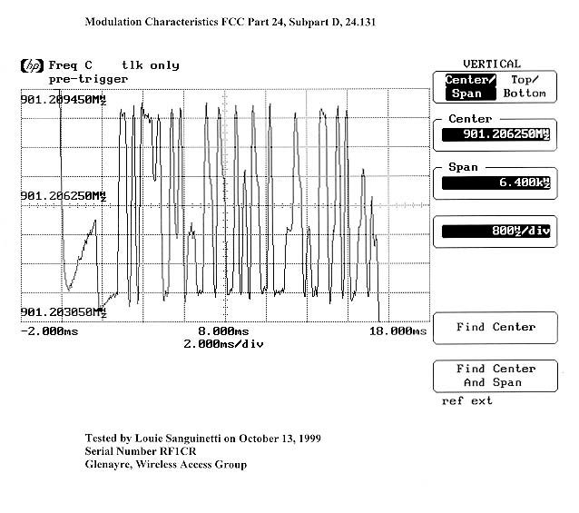
Wireless Access Group 2101 Tasman Drive Santa Clara, CA 95054 USA tel 408-653-1555 fax 408-567-1069 Modulation Characteristics: FCC Part 24, Subpart D, 24.131 • Test Conditions The pager was positioned standing on its narrow edge. This position was determined to have the worst case emissions. The HP modulation domain analyzer was configured to have a span of 6.4kHz. A registration transmission which is representative of all transmissions from the pager was captured on the modulation domain analyzer. • List of Test Equipment 1. Modulation Domain Analyzer, Hewlett Packard, Model No. 53310A, S/N 3105A00303. Calibration date: January 28, 1999. Calibration due date: January 28, 2000. • Diagram of Test Setup RF INPUT
Test Report
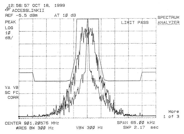
Wireless Access Group 2101 Tasman Drive Santa Clara, CA 95054 USA tel 408-653-1555 fax 408-567-1069 Occupied Bandwidth: FCC Part 24, Subpart D, 24.131 • Test Conditions The pager was positioned standing on its narrow edge. This position was determined to have the worst case emissions. The HP spectrum analyzer was configured for a resolution bandwidth of 300Hz and a span of 65kHz. All spectrum analyzer measurements were made using the Peak detector function. The spectrum analyzer reference level was set to the unmodulated (carrier only) peak power level. This was done by starting a test routine on the pager that generates carrier only. This reference trace was stored in the memory of the spectrum analyzer. Next, internal test code was started in the pager that continuously modulates the transmitter with pseudo-random data. An overlay of the carrier only spectrum, the occupied BW, and the FCC mask was plotted from the spectrum analyzer. • List of Test Equipment 1. Spectrum Analyzer, Hewlett Packard, Model No. 8594E, S/N 3911A06947. Calibration date: May 3, 1999. Calibration due date: May 3, 2000. • Diagram of Test Setup RF INPUT
Test Report
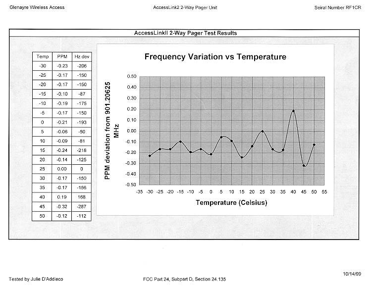
Wireless Access Group 2101 Tasman Drive Santa Clara, CA 95054 USA tel 408-653-1555 fax 408-567-1069 Frequency Variation vs. Temperature: FCC Part 24, Subpart D, 24.135 • Test Conditions The pager was positioned standing on its narrow edge inside of a Thermotron temperature test chamber. The pager was programmed such that all transmissions from the pager were unmodulated (carrier only) in order to facilitate accurate measurements of the carrier frequency. The HP modulation domain analyzer was configured to have a span of 6.4kHz. A registration transmission which is representative of all transmissions from the pager was captured on the modulation domain analyzer at temperatures between –30 and +50°C in 5°C steps. The carrier frequency deviation was measured from the modulation domain analyzer capture. • List of Test Equipment 1. Modulation Domain Analyzer, Hewlett Packard, Model No. 53310A, S/N 3105A00303. Calibration date: January 28, 1999. Calibration due date: January 28, 2000. 2. Temperature Test Chamber, Thermotron, Model No. S8C, S/N 23834. Calibration date: October 28, 1998. Calibration due date: October 28, 1999. • Diagram of Test Setup RF INPUT
Test Report
Report No: FC99-034 Page 1 of 13 CERTIFICATION TEST REPORT FOR THE 2-WAY PAGER, ACCESSLINKII (TRANSMITTER PORTION ONLY) FCC PARTS 2 AND 24 COMPLIANCE DATE OF ISSUE: NOVEMBER 10, 1999 PREPARED FOR: Glenayre Electronics, Inc. 2101 Tasman Drive Santa Clara, CA 95054 P.O. No: L7217 W.O. No: 72747 PREPARED BY: Joyce Walker CKC Laboratories, Inc. 5473A Clouds Rest Mariposa, CA 95338 Date of test: October 11, 1999 Report No: FC99-034 DOCUMENTATION CONTROL: Tracy Phillips Documentation Control Supervisor CKC Laboratories, Inc. APPROVED BY: Dennis Ward Director of Laboratories CKC Laboratories, Inc. This report contains a total of 13 pages and may be reproduced in full only. Partial reproduction may only be done with the written consent of CKC Laboratories, Inc. Report No: FC99-034 Page 2 of 13 TABLE OF CONTENTS FOR CERTIFICATION TEST REPORT Administrative Information .............................................................................................................3 Summary Of Results........................................................................................................................4 Equipment Under Test (EUT) Description......................................................................................4 Measurement Uncertainty................................................................................................................4 Peripheral Devices ...........................................................................................................................4 2.1033(c)(4) – Type(s) of Emissions ...............................................................................................5 2.1033(c)(5) – Frequency Range .....................................................................................................5 2.1033(c)(6) – Range of Operating Power ......................................................................................5 2.1033(c)(7) – Maximum Power Rating..........................................................................................5 2.1033(c)(8) – DC Voltages ............................................................................................................5 2.1033(c)(9) – Tune-Up Procedure .................................................................................................5 2.1033(c)(10) – Frequency Stabilization, Modulation, & Spurious Radiation ...............................5 2.1033(c)(13) – Description of Modulation ....................................................................................5 2.1033(c)(14)/2.1046 - RF Power Output .......................................................................................6 2.1033(c)(14)/2.1047(a) - Modulation Characteristics - Audio Frequency Response ..................10 2.1033(c)(14)/2.1047(b) - Modulation Characteristics – Modulation Limiting Response............10 2.1033(c)(14)/2.1049 - Occupied Bandwidth................................................................................10 2.1033(c)(14)/2.1051 - Spurious Emissions at Antenna Terminal ................................................10 2.1033(c)(14)/2.1053 - Field Strength of Spurious Radiation.......................................................11 2.1033(c)(14)/2.1055/101.107- Frequency Stability .....................................................................13 Report No: FC99-034 Page 3 of 13 ADMINISTRATIVE INFORMATION DATE OF TEST: Date of test: October 11, 1999 PURPOSE OF TEST: To demonstrate the compliance of the 2- Way Pager, AccessLinkII with the requirements for devices under FCC Parts 2 and 24. MANUFACTURER: Glenayre Electronics, Inc. REPRESENTATIVE: Louie Sanguinetti TEST LOCATION: CKC Laboratories, Inc. 1653 Los Viboras Road Hollister, CA 95023 TEST PERSONNEL: Art Rice TEST METHOD: FCC Part 2 and Part 24 EQUIPMENT UNDER TEST:2-WAY PAGER Manuf: Glenayre Electronics, Inc. Model: AccessLinkII Serial: RF1CR FCC ID: K3N6000 (pending) Report No: FC99-034 Page 4 of 13 SUMMARY OF RESULTS The 2-Way Pager, AccessLinkII, was tested in accordance with FCC Part 2 and Part 24 for compliance with the transmitter characteristic requirements of the FCC Rules. As received, the above equipment was found to be fully compliant with the limits of FCC Parts 2 and 24. EQUIPMENT UNDER TEST (EUT) DESCRIPTION The AccessLinkII 2-way pager. MEASUREMENT UNCERTAINTY Associated with data in this report is a ±4dB measurement uncertainty. PERIPHERAL DEVICES The EUT was not tested with any peripheral devices. Report No: FC99-034 Page 5 of 13 2.1033(c)(4) – Type(s) of Emissions 10K0F1D 2.1033(c)(5) – Frequency Range 901 – 902 MHz 2.1033(c)(6) –Range of Operating Power The operating RF output power (ERP) is 0.8872 watts. The output power is fixed. There is no means provided for variation of the operating power. 2.1033(c)(7) – Maximum Power Rating The maximum power rating as defined in § 24.132(a) is 7 watts E.R.P. The 2-Way Pager, AccessLinkII has a maximum power rating of 0.8872 watts. 2.1033(c)(8) - DC Voltages The transmitter in the AccessLinkII is powered by a 3.6V NiCad battery internal to the unit. The NiCad battery supplies a DC voltage of 3.6V and a current of 700mA to the final RF power amplifier stage. 2.1033(c)(9) – Tune-Up Procedure There is no tune-up procedure for the output power as it is fixed to the maximum output power supplied by the final RF power amplifier stage. There is no means provided for variation of the operating power. 2.1033(c)(10) – Frequency Stabilization, Modulation, & Spurious Radiation This section has been provided to the FCC per a separate file due to confidentiality reasons. 2.1033(c)(13) – Description of Modulation This section has been provided to the FCC per a separate file due to confidentiality reasons. Report No: FC99-034 Page 6 of 13 2.1033(c)(14)/2.1046 - RF Power Output Test Data Sheet: Test Location:CKC Laboratories, Inc. • 1653 Los Viboras Rd., Site A • Hollister, Ca 95023 • (831) 637-0485 Customer: Glenayre Electronics, Inc. Spe…
Text truncated - open the document above for the full version.
Contact Information
Applicant
Louie Sanguinetti(Director of Engineering)
Technical Contact
CKC Laboratories, Inc.Tracy Phillips
[email protected]1-800-500-4362
5473A Clouds Rest · Mariposa, California · United States
Non-Technical Contact
CKC Laboratories, Inc.Joyce Walker
[email protected]1-800-500-4362
Test Firm
CKC Laboratories, Inc.Steve Behm
Technical Specifications
| # | Rule Parts | Frequency Range | Power Output | Emission | Tolerance |
|---|---|---|---|---|---|
| 1 | 24D | 901 MHz - 902 MHz | 887.20 mW | 10K0F1D | 0.0001000000 % |
Other Applications from Glenayre Electronics Inc.
K3N8000
Dec 27, 2001Reflex Location Device, @ctiveFind
Equipment Class
PCB - PCS Licensed Transmitter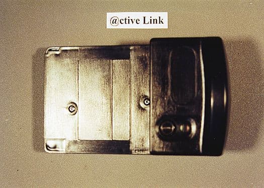
K3N7000
Aug 08, 2000ActiveLink Module
Equipment Class
PCT - PCS Licensed Transmitter worn on body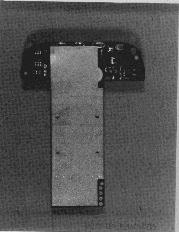
K3N5000
Aug 19, 1998PCT - PCS Licensed Transmitter worn on body
Equipment Class
PCT - PCS Licensed Transmitter worn on bodyK3N3000
Mar 17, 1996Two-Way Pager
Equipment Class
JBP - Part 15 Class B Computing Device PeripheralK3N-ACCESSCARD-GX
Mar 16, 1994PCMCIA Paging Receiver
Equipment Class
CXX - Communications Rcvr for use w/ licensed Tx and CBs