K3N8000Reflex Location Device, @ctiveFind
Glenayre Electronics Inc.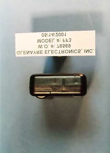
Click to zoom
Application Details
- Equipment Class
- PCB - PCS Licensed Transmitter
- Date of Grant
- Dec 27, 2001
- Application Purpose
- Original Equipment
- Date of Application
- Sep 25, 2001
- Equipment Note
- Reflex Location Device, @ctiveFind
- Frequency Range
- 901.00000000 - 902.00000000
- Company
- Glenayre Electronics Inc.
- Country
- United States
Documents & Files
Document Text
Text extracted from the exhibit documents filed with the FCC. Open a document above to read the original.
Users Manual
@ctiveFind ™ User Guide 2 Contents Finding the assets you care about. . . . . . . . . . . . . . . . . . . . .3 Setting up or changing account information . . . . . . . . . . . . .4 Battery Information . . . . . . . . . . . . . . . . . . . . . . . . . . . . . . . .6 Turning the @ctiveFind device on and off . . . . . . . . . . . . . . .8 Attaching the @ctiveFind device . . . . . . . . . . . . . . . . . . . . . .9 Interpreting the LEDs and buzzer . . . . . . . . . . . . . . . . . . . .10 How to find an @ctiveFind device . . . . . . . . . . . . . . . . . . . .12 How to be found when you carry the device . . . . . . . . . . . .13 Specifications . . . . . . . . . . . . . . . . . . . . . . . . . . . . . . . . . . .14 Questions and answers . . . . . . . . . . . . . . . . . . . . . . . . . . . .16 3 Finding the assets you care about With your new @ctiveFind device you can: •Quickly find a valuable asset that is carrying a location device by making a location fix request via a phone, two-way pager, or secure website. Because this location service integrates GPS navigation technology, a two-way wireless messaging network, and the internet, it has enhanced accuracy, coverage, and accessibility. It can work in places that other location systems cannot — for example, in cities and indoors. You have access to these alert-sending and location-finding services 24 hours a day, 365 days a year. Use the information in this guide to get acquainted with the device’s features. Then use the world’s smallest, most accurate portable location device to locate what you care about. WarningThe @ctiveFind device provides the best coverage that current location technology can offer, but it does not work everywhere. If the device is in an area of poor network or GPS coverage or in certain indoor locations (for example, an elevator), it may not provide a location fix. WarningDuring normal use this device is not to be located within 20 cm (8 inches) of a person. It is intended for Asset Tracking only. 4 Setting up or changing account information In addition to providing the usual account identification and billing information, you will need to let your service provider know what action to take when they receive a message from your @ctiveFind device. You can configure up to three separate responses. Typically these instructions would be to send a location alert message to a designated contact by e-mail, phone, or pager. Your service provider can also send an alert message to your device. You can set up your account to specify what this alert will indicate and under what circumstances it will be sent. (Note that this alert will not be muted by standby mode —see page 8.) Before you contact your service provider about your account, be prepared with the following information. You may want to make a note of this information, either here or in a more secure place: • Account ID: ___________________________________________________ • Device ID: ____________________________________________________ • Password: ____________________________________________________ • Action your service provider will perform when you press: Button 1: _____________________________________________________ Button 2: _____________________________________________________ Both buttons: __________________________________________________ • What a network alert indicates: 5 LED Button 2 Button 1 6 Battery Information Your @ctiveFind device needs one AA battery. Battery life is affected by several factors, including: • Cold weather • Quality of the battery • Number of location fixes performed • Number of times the alerts are used • Type of battery — Although alkaline batteries are recommended for general use, the @ctiveFind device can also use other types of batteries (such as lithium) that have a longer lifespan. Ask your service provider for details. Note Non-alkaline batteries may require special disposal procedures. When the battery needs to be replaced, the device will provide two short beeps every 60 seconds if your service provider has enabled the buzzer. ➤To install the battery 1Remove the battery compartment door. 2Insert one AA battery, aligning the + and - symbols on the battery with those in the battery compartment. 3Replace the battery compartment door. 7 8 Turning the @ctiveFind device on and off Depending on how your service provider has configured this feature, the On/Off switch can have up to three modes: The Standby mode, which allows your service provider to override the On/Off switch setting, ensures that devices inadvertently turn the switch off can still be located. On• The device can perform a location fix • The LED and buzzer are enabled Off• The device cannot perform a location fix • The LED and buzzer are disabled Off (Standby)• The device can perform a location fix • The LED and buzzer are disabled (except for the network alert) 9 Attaching the @ctiveFind device The @ctiveFind device has been designed to make it easy to be placed in or on a valuable item. A built-in chain post and a belt clip help to secure the device to the item carrying it. When positioning the device on the item, try to keep the device pointed upwards for optimal performance. In addition, keep these precautions in mind: • The device should be kept away from metal objects. • The device can operate in temperatures ranging from -10 to +50 degrees Celsius (14 to 122 degrees Fahrenheit), but it will not operate for extended periods of time below 0 degrees Celsius (32 degrees Fahrenheit). 10 Interpreting the LEDs and buzzer The LEDs and buzzer give you information about the device and the progress of location fixes. The table shows the factory settings. Your service provider may have customized these or enabled only the LED or only the buzzer. AlertWhat it means Green LED Three increasingly long flashes The @ctiveFind has network coverage (occurs when the user changes the switch from Standby to On). A location fix is possible. Short flashes, every five seconds Full network…
Text truncated - open the document above for the full version.
Cover Letter(s)
Vancouver Facility 1570 KootenayStreet Vancouver, British Columbia V5K 5B8 CANADA telephone: 604-293-1611 www.glenayre.com August 6, 2001 Federal Communications Commission 7435 Oakland Mills Road Columbia, MD 21046 USA Confidentiality of Material Request This letter is to comply with Section O.457(d)(2)(i) pertaining to confidential material. Glenayre Electronics, Inc., would like the following documents regarding this submission for FCC ID: K3N8000 to be kept confidential. 1. Schematics (RF -7 Piles: 2000-02508; BB -4 Files: 2000-02536) 2. Modulation Characteristics -1 File 3. Occupied Bandwidth -1 File 4. Frequency Stability -2 Files The above material contains trade secrets or technical data, which would customarily be guarded from competitors. We do not want these documents to be accessible to the general public. Sincerely, Compliance Engineer Telephone: (604) 293-5290 Applicant: Glenayre Electronics, Inc. Communication Innovations. TM
Cover Letter(s)
Wireless Messaging Group 1570 Kootenay Street Vancouver, British Columbia V5K 5BB CANADA telephone: 604-293-1611 www.glenayre.com November 20,2001 Federal Communications Commission 7435 Oakland Mills Road Columbia, MD 21046 USA Confidentiality of Material ReQuest This letter is to comply with Section 0.457( d)(2)(i) pertaining to confidential material. Glenayre Electronics, Inc., would like the following docwnents regarding this submission for FCC ID: K3N8000 to be kept confidential. Schematics (RF -7 Files: 2000-02508; BB -4 Files: 2000-02536) Theory of Operation -1 File I. 2. The above material contains trade secrets or technical data, which would customarily be guarded from competitors. We do not want these documents to be accessible to the general public. Sincerely, Compliance Engineer (604) 293-5290 Telephone: Glenayre Electronics, Inc. Applicant: Communication Innovations.TM
Test Report
Vancouver Facility 1570 Kootenay Street Vancouver, British Columbia V5K 5B8 CANADA telephone: 604-293-1611 www.g le nayre .co m Modulation Characteristics: FCC Part 24, Subpart D, 24.131 FCC Part 90, Subpart I, 90.209 • Test Conditions The @ctiveFind device was placed in holster position inside a TEM cell. This position was previously determined to have the worst case emissions. The HP modulation domain analyzer was configured to have a span of 6.4 kHz. An acknowledgement transmission, which is representative of all transmissions from the device, was captured on the modulation domain analyzer. • List of Test Equipment 1. Modulation Domain Analyzer, Hewlett Packard, Model No. 53310A, S/N 3105A00371. Calibration date: July 28, 2000. Calibration due date: July 28, 2001. 2. TEM Cell, Tescom, Model No. TC-5060B, S/N 5060B140093. Calibration date: April 17, 2001. Calibration due date: October 17, 2001. • Diagram of Test Setup RF INPUT @ctiveFind under test TEM cell Vancouver Facility 1570 Kootenay Street Vancouver, British Columbia V5K 5B8 CANADA telephone: 604-293-1611 www.g le nayre .co m @ctiveFind Device Serial Number: 050135 Tested by: Brent Pearce FCC Part 24, Subpart D, 24.131 Vancouver Facility 1570 Kootenay Street Vancouver, British Columbia V5K 5B8 CANADA telephone: 604-293-1611 www.g le nayre .co m @ctiveFind Device Serial Number: 050135 Tested by: Brent Pearce FCC Part 90, Subpart I, 90.209 Vancouver Facility 1570 Kootenay Street Vancouver, British Columbia V5K 5B8 CANADA telephone: 604-293-1611 www.g le nayre .co m @ctiveFind Device Serial Number: 050135 Tested by: Brent Pearce FCC Part 90, Subpart I, 90.209
Test Report
Vancouver Facility 1570 Kootenay Street Vancouver, British Columbia V5K 5B8 CANADA telephone: 604-293-1611 www.g le nayre .co m Occupied Bandwidth: FCC Part 24, Subpart D, 24.133 FCC Part 90, Subpart I, 90.210 • Test Conditions The @ctiveFind device was placed in holster position inside a TEM cell. This position was previously determined to have the worst case emissions. The HP vector signal analyzer was configured as a spectrum analyzer with a resolution bandwidth of 300 Hz and a span of 65 kHz. All spectrum analyzer measurements were made using the Peak detector function. The spectrum analyzer reference level was set to the unmodulated (carrier only) peak power level. This was done by starting a test routine on the device that generates carrier only. This reference trace was stored in the memory of the spectrum analyzer. Next, internal test code was started in the device that continuously modulates the transmitter with 9600 bps pseudo- random data. An overlay of the carrier-only spectrum, the modulated spectrum, and the FCC mask was plotted from the spectrum analyzer. • List of Test Equipment 1. Vector Signal Analyzer, Hewlett Packard, Model No. 89441A, S/N 3416A00986. Calibration date: May 6, 2001. Calibration due date: June 6, 2002. 2. TEM Cell, Tescom, Model No. TC-5060B, S/N 5060B140093. Calibration date: April 17, 2001. Calibration due date: October 17, 2001. • Diagram of Test Setup RF INPUT HP89441A Vector Signal Analyzer @ctiveFind under test TEM cell Vancouver Facility 1570 Kootenay Street Vancouver, British Columbia V5K 5B8 CANADA telephone: 604-293-1611 www.g le nayre .co m @ctiveFind Device Serial Number: 050135 Tested by: Brent Pearce FCC Part 24, Subpart D, 24.133 Vancouver Facility 1570 Kootenay Street Vancouver, British Columbia V5K 5B8 CANADA telephone: 604-293-1611 www.g le nayre .co m @ctiveFind Device Serial Number: 050135 Tested by: Brent Pearce FCC Part 90, Subpart I, 90.210 Emission Mask J Vancouver Facility 1570 Kootenay Street Vancouver, British Columbia V5K 5B8 CANADA telephone: 604-293-1611 www.g le nayre .co m @ctiveFind Device Serial Number: 050135 Tested by: Brent Pearce FCC Part 90, Subpart I, 90.210 Emission Mask J
Test Report
Glenayre Electronics, Inc. @ctiveFind Device Serial Number: 049827 Temp. PPM Hz Offset 50 -0.002 -2.0 40 -0.010 -9.0 30 -0.008 -7.0 20 -0.004 -4.0 10 -0.011 -10.0 0 0.004 4.0 -10 0.007 6.0 -20 N/A* N/A -30 N/A N/A Note: * Device does not transmit at temperatures below -15C. Frequency Offset vs. Temperature -0.500-0.400-0.300-0.200-0.100 0.0000.1000.2000.3000.4000.500 -35 -30 -25 -20 -15 -10 -5 0 5 10 15 20 25 30 35 40 45 50 55 Temperature (Celsius) PPM offset from 901.20625 MHz Tested by: Mark Finlay FCC Part 24, Subpart D, 24.135 August 31, 2001
Test Report
Vancouver Facility 1570 Kootenay Street Vancouver, British Columbia V5K 5B8 CANADA telephone: 604-293-1611 www.g le nayre .co m Frequency Stability: FCC Part 24, Subpart D, 24.135 • Test Conditions The @ctiveFind device was placed in holster position inside a temperature test chamber with an external 1.10Vdc power supply replacing the AA battery. The device was programmed such that all transmissions from it were unmodulated (carrier only) for the first 15 ms in order to facilitate accurate measurements of the carrier frequency. An acknowledgement transmission, which is representative of all transmissions from the device, was captured on the vector signal analyzer at temperatures between –30 and +50°C in 10°C steps. The carrier frequency offset was measured from the vector signal analyzer capture. • List of Test Equipment 1. Vector Signal Analyzer, Hewlett Packard, Model No. 89441A, S/N 3416A00986. Calibration date: May 6, 2001. Calibration due date: June 6, 2002. 2. Temperature Test Chamber, Tenney Environmental, Model No. TUJR, S/N 27503-04. Calibration date: September 26, 2000. Calibration due date: September 26, 2001. 3. Power Supply, Xantrex, Model No. HPD15-20S, S/N 13702. Calibration date: April 17, 2001. Calibration due date: April 17, 2002. • Diagram of Test Setup RF INPUT @ctiveFind under test Tenney Temperat ure Test Chamber Xantrex HPD15-20S Power Supply + _ HP 89441A Vector Signal Analyzer
Test Report
Page 1 of 22 Report No.: FC01-052A ADDENDUM TO TEST REPORT FC01-052 FOR THE REFLEX LOCATION DEVICE, @CTIVEFIND FCC PART 24 SUBPART D AND FCC PART 15 SUBPART B SECTION 15.109 CLASS B COMPLIANCE DATE OF ISSUE: SEPTEMBER 4, 2001 PREPARED FOR: Glenayre Electronics, Inc. 1570 Kootenay Street Vancouver, BC, V5K 5B8 PREPARED BY: Joyce Walker CKC Laboratories, Inc. 5473A Clouds Rest Mariposa, CA 95338 P.O. No.: 13286 W.O. No.: 76569 Date of test: May 14-22, 2001 Report No.: FC01-052A This report contains a total of 22 pages and may be reproduced in full only. Partial reproduction may only be done with the written consent of CKC Laboratories, Inc. Page 2 of 22 Report No.: FC01-052A TABLE OF CONTENTS Administrative Information ............................................................................................. 3 Summary of Results......................................................................................................... 4 Modifications Required for Compliance ......................................................................... 4 Approvals......................................................................................................................... 4 Equipment Under Test (EUT) Description...................................................................... 5 Equipment Under Test..................................................................................................... 5 Peripheral Devices ........................................................................................................... 5 Temperature and Humidity During Testing .................................................................... 5 2.1033(c)(3) User’s Manual ............................................................................................ 6 2.1033(c)(4) Type of Emissions ...................................................................................... 6 2.1033(c)(5) Frequency Range ........................................................................................ 6 2.1033(c)(6) Operating Power ......................................................................................... 6 2.1033(c)(7) Maximum Power Rating............................................................................. 6 2.1033(c)(8) DC Voltages ............................................................................................... 6 2.1033(c)(9) Tune-Up Procedure .................................................................................... 6 2.1033(c)(10) Schematics and Circuitry Description ...................................................... 6 2.1033(c)(11) Label and Placement................................................................................. 7 2.1033(c)(12) Submittal Photos....................................................................................... 7 2.1033(c)(13) Modulation Information ........................................................................... 7 2.1033(c)(14)/2.1046/24.132(a) RF Power Output ......................................................... 8 2.1033(c)(14)/2.1047(b)/24.131 - Modulation Characteristics - Audio .......................... 13 2.1033(c)(14)/2.1047(b)/24.131 - Modulation Characteristics - Limits.......................... 13 2.1033(c)(14)/2.1049(i)/24.131 - Occupied Bandwidth .................................................. 13 2.1033(c)(14)/2.1051/N/A - Spurious Emissions at Antenna Terminal .......................... 13 2.1033(c)(14)/2.1053/24.133 - Field Strength of Spurious Radiation............................. 14 2.1033(c)(14)/2.1055/24.131 - Frequency Stability ........................................................ 16 15.109 – Radiated Emissions .......................................................................................... 16 Page 3 of 22 Report No.: FC01-052A CKC Laboratories, Inc. has received Certificates of Accreditation from the following agencies: A2LA (USA); DATech (Germany); BSMI (Taiwan); Nemko (Norway); and GOST (Russia). CKC Laboratories, Inc has received test site Registration Acceptance from the following agencies: FCC (USA); VCCI (Japan); and Industry Canada. CKC Laboratories, Inc. has received Letters of Acceptance through an MRA for the following agencies: ACA/NATA (Australia); SABS (South Africa); SWEDAC (Sweden); Radio Communications Agency (RA); HOKLAS (Hong Kong); Bakom (Swiss); BIPT (Belgium); Denmark Telestyrelsen; RvA (Netherlands); SEE (Luxembourg) SITTEL (Bolivia); and UKAS (UK). ADMINISTRATIVE INFORMATION DATE OF TEST: May 14-22, 2001 DATE OF RECEIPT: May 14, 2001 PURPOSE OF TEST: To demonstrate the compliance of the ReFLEX Location Device, @ctiveFind with the requirements for FCC Part 24 Subpart D and Part 15 Subpart B Section 15.109 Class B devices. This addendum is to add the calculations used for power output and to remove the engineering GPS receiver data that is not required per the specifications. TEST METHOD: FCC Parts 2, 15 & 24, ANSI C63.4 (1992) MANUFACTURER: Glenayre Electronics, Inc. 1570 Kootenay Street Vancouver, BC, V5K 5B8 REPRESENTATIVE: Rick Hiebert TEST LOCATION: CKC Laboratories, Inc. 1653 Los Viboras Road Hollister, CA 95023 Page 4 of 22 Report No.: FC01-052A SUMMARY OF RESULTS As received, the Glenayre Electronics, Inc. ReFLEX Location Device, @ctiveFind was found to be fully compliant with the following standards and specifications: United States ! FCC Part 24 Subpart D ! FCC Part 15 Subpart B Section 15.109 Class B ANSI C63.4 (1992) method Canada RSS-134 using: ! FCC Part 24 Subpart D ! FCC Part 15 Subpart B Section 15.109 Class B ANSI C63.4 (1992) method The results in this report apply only to the items tested, as identified herein. MODIFICATIONS REQUIRED FOR COMPLIANCE No modifications to the EUT were necessary to comply. APPROVALS QUALITY ASSURANCE:TEST PERSONNEL: Dennis Ward, Quality ManagerConan T. Boyle, EMC Engineer Christine Nicklas, EMC/Lab Manager Page 5 of 22 Report No.: FC01-052A EQUIPMENT UNDER TEST (EUT) DESCRIPTIO…
Text truncated - open the document above for the full version.
Contact Information
Applicant
Louie Sanguinetti(Director of Engineering)
Technical Contact
CKC Laboratories, Inc.Joyce Walker
[email protected]800-500-4362
5473A Clouds Rest · Mariposa, California · United States
Test Firm
CKC Laboratories, Inc.Steve Behm
Technical Specifications
| # | Rule Parts | Frequency Range | Power Output | Emission | Tolerance |
|---|---|---|---|---|---|
| 1 | 24D | 901 MHz - 902 MHz | 267.00 mW | 10K0F1D | 0.0160000000 ppm |
Other Applications from Glenayre Electronics Inc.
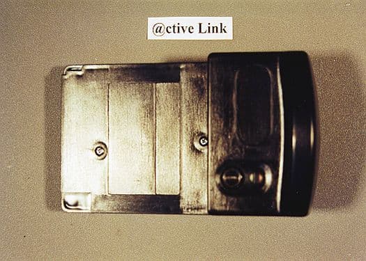
K3N7000
Aug 08, 2000ActiveLink Module
Equipment Class
PCT - PCS Licensed Transmitter worn on body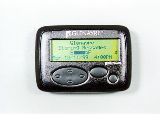
K3N6000
Feb 21, 2000AccessLinkII 2-Way Pager
Equipment Class
PCT - PCS Licensed Transmitter worn on body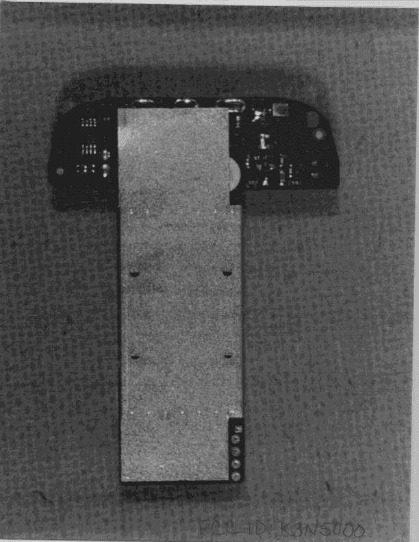
K3N5000
Aug 19, 1998PCT - PCS Licensed Transmitter worn on body
Equipment Class
PCT - PCS Licensed Transmitter worn on bodyK3N3000
Mar 17, 1996Two-Way Pager
Equipment Class
JBP - Part 15 Class B Computing Device PeripheralK3N-ACCESSCARD-GX
Mar 16, 1994PCMCIA Paging Receiver
Equipment Class
CXX - Communications Rcvr for use w/ licensed Tx and CBs