K3N7000ActiveLink Module
Glenayre Electronics Inc.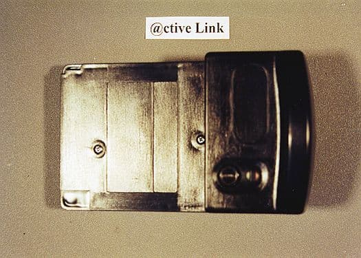
Click to zoom
Application Details
- Equipment Class
- PCT - PCS Licensed Transmitter worn on body
- Date of Grant
- Aug 08, 2000
- Application Purpose
- Original Equipment
- Date of Application
- Jun 15, 2000
- Equipment Note
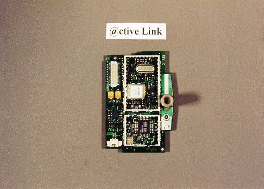
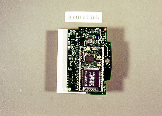
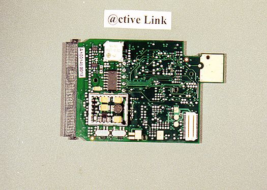
- ActiveLink Module
- Frequency Range
- 896.00000000 - 902.00000000
- Company
- Glenayre Electronics Inc.
- Country
- United States
Documents & Files
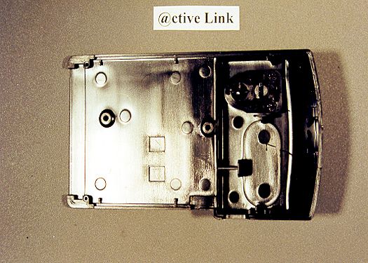
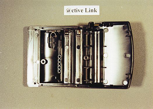
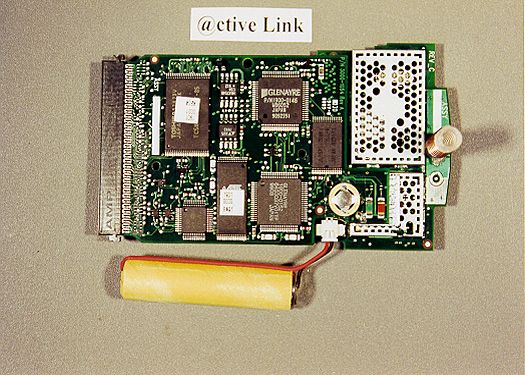
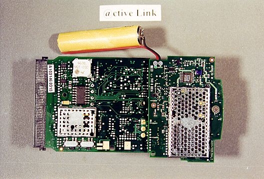
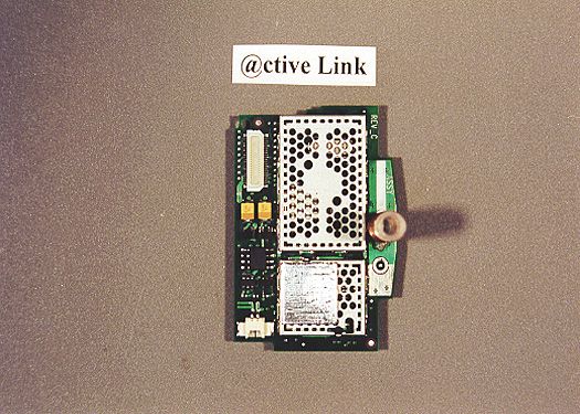
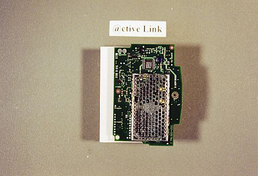
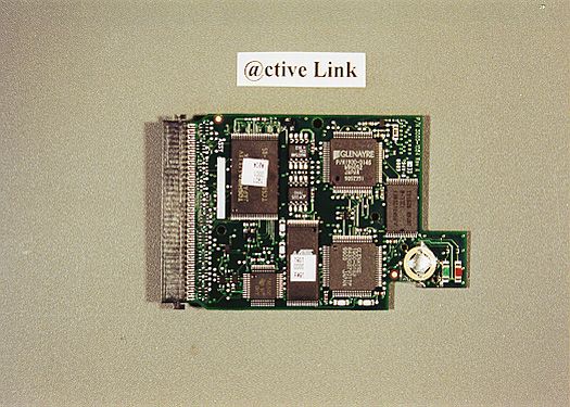
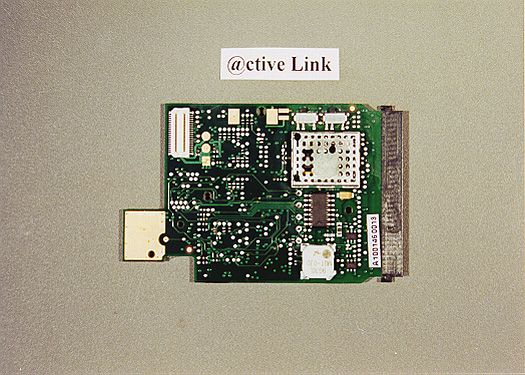
Document Text
Text extracted from the exhibit documents filed with the FCC. Open a document above to read the original.
Users Manual
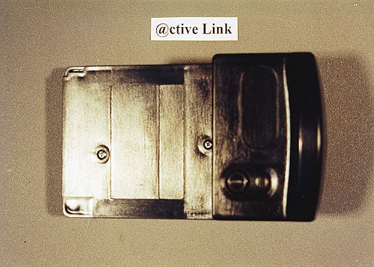
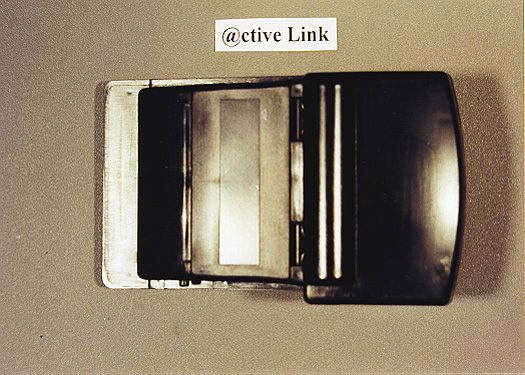
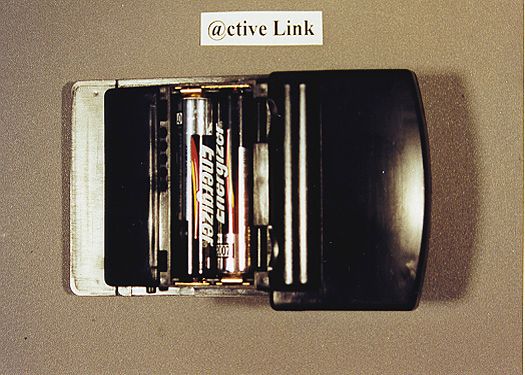
PN 9110.01417 REV 1.0 April 18, 2000 1 of 8 © 2000 Glenayre Electronics, @ctiveLink Module Glenayre’s @ctiveLink TM Springboard TM Expansion Module converts your Visor TM Handheld into an interactive mobile communication device. The @ctiveLink module works both indoors and out, giving you a reliable, wireless connection to your office, home, and the internet. The @ctiveLink module is constantly on and communicating, giving you access to any Internet- based messaging and information services your wireless carrier supports. When you insert it into the Springboard expansion slot, the Visor Handheld’s user interface screen displays your incoming communications and lets you compose and send your own messages. Even when the the @ctiveLink module is removed from the Visor Handheld, it maintains your wireless link. It continues to collect new messages, storing them in the module’s onboard memory. It uses flashing LEDs and/or optional audible alerts to notify you of message arrival. Use the information in this booklet to set up your @ctiveLink module and get acquainted with its features. Then use your new wireless device to stay in touch, anywhere. The first time you use your @ctiveLink module you need to: •Install the batteries (see page 1) •Turn your @ctiveLink module on (see page 3) •Insert the @ctiveLink module into the Springboard expansion slot (see page 3) •Configure your handheld (see page 5) •Contact your wireless carrier to activate two-way service for your module (see page 5) Any time you use your @ctiveLink module you may need to know how to do the following: •Launch the application (see page 5) •Silence any audible message alerts (see page 5) •Check out your network coverage (see page 6) •Read the LEDs (see page 7) •Remove @ctiveLink from the Springboard slot (see page 7) •Turn the @ctiveLink module off (see page 8) Putting Batteries into the @ctiveLink Module 1.Place your fingers on the two door latches and pull the door towards you, lifting it off the Module. @CTIVELINK MODULE PN 9110.01417 REV 1.0 Release Date 2 of 8 © 2000 Glenayre Electronics, 2.Place two AAA alkaline batteries into the battery compartment, aligning the + and - symbols on the batteries with the symbols in the battery compartment. 3.Align the door with the slots at the back of the Module and clip the door smoothly into place. Do not force. If you feel resistance, check to ensure the batteries are seated properly in the compartment. When battery power is low, the module’s red LED will flash quickly. Use this same procedure to replace the batteries. @CTIVELINK MODULE PN 9110.01417 REV 1.0 Release Date 3 of 8 © 2000 Glenayre Electronics, Turning the @ctiveLink Module On and Off Whether or not it is inserted in the Visor Handheld, the @ctiveLink module should always be on. When it is on, you can send and receive messages; when it is off, you can neither send nor receive. To turn the Module on, slide the power switch until it covers the word OFF. To turn it off, slide the switch to uncover the word OFF. Inserting the @ctiveLink Module into the Springboard Slot 1.Remove the slot protector from the Visor Handheld. @CTIVELINK MODULE PN 9110.01417 REV 1.0 Release Date 4 of 8 © 2000 Glenayre Electronics, 2.Insert the @ctiveLink Module into the Springboard expansion slot until the connectors are secure. @CTIVELINK MODULE PN 9110.01417 REV 1.0 Release Date 5 of 8 © 2000 Glenayre Electronics, Configuring @ctiveLink Software Inserting the @ctiveLink module into the Visor Handheld launches the software (you can also press the button to start the application). Follow the directions on the user interface screen to configure the software. You need to set up the following ??? illustration of user interface configuration screen Setting up Two-Way Wireless Service If you did not set up two-way service when you purchased the @ctiveLink module, do so now by contacting (??? a specific carrier???a wireless communications service provider in your area ???). You may need to provide some or all of the following information: •Your name, address, and telephone number •Credit information •Identification •Your device’s serial number •The service plan and billing method you prefer •The coverage area you would like Receiving Messages Whether or not your @ctiveLink is inserted into the Visor Handheld, it receives messages when its power switch is on. Depending on the Preferences settings you select in the Visor Handheld application, you will receive one of the following to let you know when a message arrives: •Musical alert •Beep •LED indicator (steady or flashing green) If the @ctiveLink module is in the Visor Handheld, it will also activate the application whenever a message arrives. When you receive notification of message arrival: 1.Press the button to clear any audible alerts. @CTIVELINK MODULE PN 9110.01417 REV 1.0 Release Date 6 of 8 © 2000 Glenayre Electronics, 2.Read the message in the user interface screen. Sending Messages If you are in an area where you have full network coverage, you can send messages. How ??? Checking Out Network Coverage If the @ctiveLink module is inserted in the Visor Handheld, you can check out your network coverage on the user interface screen (How???) If the @ctiveLink is not in the Visor Handheld, you can find out your network status by pressing and holding down the button. The LED display indicates the following: LEDWhat it means Steady greenYou have full network service. You can send and receive messages. Steady red and greenYour device can only receive messages. Sending service is temporarily interrupted. Steady redYour device is out of network range. You cannot send or receive communications. The network is storing your messages. @CTIVELINK MODULE PN 9110.01417 REV 1.0 Release Date 7 of 8 © 2000 Glenayre Electronics, Reading the LEDs If you are not depressing the button to check out your network status, the LEDs indicate the following: Removing the @ctiveLink Module 1.Depress the latch button at the side o…
Text truncated - open the document above for the full version.
Cover Letter(s)
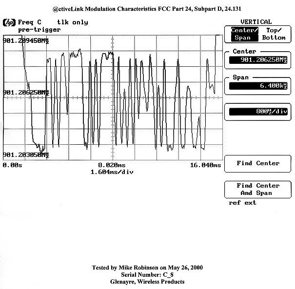
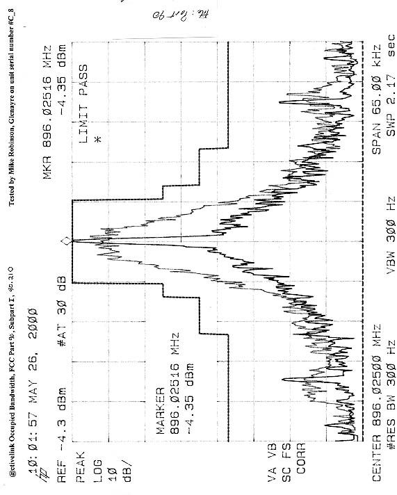
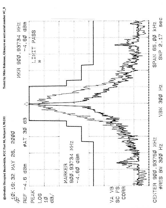
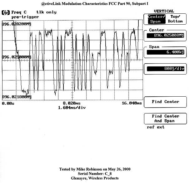
Federal Communications Commission 7435 Oakland Mills Road Columbia, MD 21046 CKC Laboratories was not certain on the requirements to handle a device that falls under two different FCC Rule Parts. The Glenayre device, Wireless Messaging Module, Model “@ctiveLink” has a frequency range of 896-902 MHz that falls under Part 24 and Part 90. CKC Labs was told by Frank Coperich in an email (email can be provided if necessary) that it could be handled in one application and that one FCC ID number would be applied. He stated that the grant would show each Rule Part and corresponding frequency range. This application is for Part 24 and a separate Permissive Change application will be uploaded with the Part 90 data included. About CKC Test Report This is to clarify where to find certain required data for this application. Our customer, Glenayre Electronics, Inc. performed some of the required testing and, therefore, will not be found in the CKC Laboratories, Inc Test Report. In the CKC Test Report there is a comment that says, “see customer supplied data”. The customer-supplied data will be uploaded as separate data files under the Test Report exhibit as follows: ♦ 2.1033(C)(14)/2.1047(B) - Modulation Characteristics - There will be two attachments: ♦ 1) Modulation plot.jpeg showing a plot ♦ 2) Modulation characteristics test conditions equipment and setup.doc providing test conditions, test equipment used, and a diagram of the test setup used that provided the plot file. ♦ 2.1033(C)(14)/2.1049(I) - Occupied Bandwidth - There will be two attachments: ♦ 1) Bandwidth plot.jpeg showing the plot. ♦ 2) Occupied bandwidth test conditions equipment and setup.doc providing test conditions, test equipment used, and a diagram of the test setup used that provided the plot file. ♦ 2.1033(C)(14)/2.1055/101.107 - Frequency Stability - There will be two attachments: ♦ 1) Frequency variation vs temp.PDF showing the plot & data. ♦ 2) Frequency variation and temp test conditions equipment and setup.doc providing test conditions, test equipment used, and a diagram of the test setup used that provided the plot file. Sincerely, Joyce Walker CKC Technical Report Writer Agent for Glenayre Electronics, Inc.
Cover Letter(s)
June 21, 2000 Federal Communications Commission 7435 Oakland Mills Road Columbia, MD 21046 Re: FCC ID: K3N7000, EA97936 The 731 application and its associated files were uploaded on June 16,2000 for Glenayre Electronics’ Wireless Messaging Module, @ctiveLink, operating under Part 24. We are also seeking approval under Part 90 for the same device. We were uncertain how to apply for two different Rule Parts on the same application. Previously we had submitted a similar device, but we were able to link them by using the Permissive Change process. However, we do not want to wait until Part 24 is granted before submitting the Part 90 application. We were instructed byone of your adminastrative staff that to upload the Part 90 information to the Part 24 application. In addition to adding Part 90 to the application, CKC Laboratories did some additional testing on the power. The unit provided for testing was not modified so that a direct connect could be made. As a result, it was very difficult to capture the same power readings while testing both Part 24 and Part 90. A unit was modified and retested recently using the direct connect method. The test report for Part 24 was amended to reflect the new test data. Please disregard test report FC00-052. Instead, use test report FC00-052A. Since the Part 24 application has already been uploaded, I cannot change or add any information to it. Please make the following changes on the 731 Form: Item #10 – under “Equipment will be operated under FCC Rule Part(s)” add Part 90. Item #12 – under “Equipment Specifications” correct the “Rated RF power output in watts” for the frequency ranges listed under 901-902 MHz from 2.80 to 1.81 watts. Add 896-902 MHz with a RF power output of 1.808 watts, 0.42 ppm for frequency tolerance and 10K0F1D for the emissions designator. Do not hesitate to contact me at [email protected] for any assistance you may require. Sincerely, Joyce Walker CKC Laboratories, Inc. Technical Report Writer
ID Label/Location Info
Glenayre, Wireless Products 2101 Tasman Drive, Santa Clara, CA 95054-1027 (408) 653-1555 fax (408) 653-1529 LABEL, @CTIVELINK, WEBLINK WIRELESS SIZE A DWG. NO.REV. 5700-2082 A SCALE:SHEET 1 OF 1 Glenayre, Wireless Products. CONFIDENTIAL AND PROPRIETARY THE INFORMATION DISCLOSED HERIN INCLUDES PROPRIETARY RIGHTS OF GLENAYRE ELECTRONICS, INC. NEITHER THIS DOCUMENT NOR THE INFORMATION DISCLOSED THERIN SHALL BE REPRODUCED OR TRANSFERRED TO OTHER DOCUMENTS OR USED OR DISCLOSED TO OTHERS FOR ANY PURPOSE EXCEPT AS SPECIFICALLY AUTHORIZED IN WRITING BY GLENAYRE. APPROVALSDATE DRAWN 6-1-00 CHECKED ENGINEERING UNLESS OTHERWISE SPECIFIED DIMENSIONS ARE IN MILLIMETERS TOLERENCES ARE: DECIMALSANGLES .XX ± 0.20± 1.0° .XXX ± --- MATERIAL: FINISH: CAD FILE: REVISIONS ECODESCRIPTIONECO DATEAPPROVED/DATEREV PRODUCTION RELEASE6-1-00A NOTES: M. Scharen SEE NOTE SEE NOTE 5700-2006RA.PPT 1 METRIC Customer Service: (800) 794-0837 8A1BL112345 6-1-00530 CONTAINS NICKEL-CADMIUM BATTERY. MUST BE RECYCLED OR DISPOSED OF PROPERLY. 1.5V AA ALK. GLENAYRE SANTA CLARA, CA CONFORMS TO UL-913 HAZ LOC CL 1 GROUPS A-D FCC ID : K3N7000 CAN : XXXXXXXXXX CAN : XXXXXXXXXX Ni-Cd 9800401 FCA : XXXXXX
RF Exposure Info
Intertek Testing ServicesDate of Test: 5/23/00 900 MHz Wireless Messaging Module for Handspring Visor PDAModel: @ctive Link Report # J20014404_SAR4FCC Part 2 SAR Evaluation 1.3 Test plan reference FCC rule part 2.1093, FCC Docket 96-326 & Supplement C to OET Bulletin 65 1.4 System test configuration 1.4.1 System block diagram & Support equipment The diagram shown below details test configuration of the equipment under test . EUT Face UpEUT Face Down EUT With PDAEUT With PDA S: Shielded U: Unshielded F: With Ferrite Core Support equipment Equp. #EquipmentManufacturerModel #S/N #FCC ID 1Power SuppliesTopward Electric InstrumentTPS-4000917003N/A EUT (1) 1m, S Intertek Testing ServicesDate of Test: 5/23/00 900 MHz Wireless Messaging Module for Handspring Visor PDAModel: @ctive Link Report # J20014404_SAR5FCC Part 2 SAR Evaluation 1.4.2 Test Position The EUT was configured for testing in a typical fashion (as a customer would normally use it), and in the confines as outlined in C95.1 (1992) and Supplement C of OET 65 (1998). The EUT was placed in the intended use position, i.e. touching the human body or hand. Please refer to figure 1 below for the position details: Side ViewTop View Figure 1: Intended use position Flat Phantom EUT Flat Phantom EUT Connector Interface to PDA Antenna Antenna Intertek Testing ServicesDate of Test: 5/23/00 900 MHz Wireless Messaging Module for Handspring Visor PDAModel: @ctive Link Report # J20014404_SAR8FCC Part 2 SAR Evaluation 2.2 Configuration Photographs Face Up Intertek Testing ServicesDate of Test: 5/23/00 900 MHz Wireless Messaging Module for Handspring Visor PDAModel: @ctive Link Report # J20014404_SAR9FCC Part 2 SAR Evaluation Configuration Photographs – Continued Face Down Intertek Testing ServicesDate of Test: 5/23/00 900 MHz Wireless Messaging Module for Handspring Visor PDAModel: @ctive Link Report # J20014404_SAR10FCC Part 2 SAR Evaluation Configuration Photographs – Continued Face Down Low Section Intertek Testing ServicesDate of Test: 5/23/00 900 MHz Wireless Messaging Module for Handspring Visor PDAModel: @ctive Link Report # J20014404_SAR11FCC Part 2 SAR Evaluation Configuration Photographs – Continued Face Down Up Section Intertek Testing ServicesDate of Test: 5/23/00 900 MHz Wireless Messaging Module for Handspring Visor PDAModel: @ctive Link Report # J20014404_SAR12FCC Part 2 SAR Evaluation Configuration Photographs – Continued With PDA Face Up Intertek Testing ServicesDate of Test: 5/23/00 900 MHz Wireless Messaging Module for Handspring Visor PDAModel: @ctive Link Report # J20014404_SAR13FCC Part 2 SAR Evaluation Configuration Photographs – Continued With PDA Face Down
RF Exposure Info
Intertek Testing Services Date of Test: 5/23/00 900 MHz Wireless Messaging Module for Handspring Visor PDAModel: @ctive Link Report # J20014404_SAR 24 FCC Part 2 SAR Evaluation Intertek Testing Services Date of Test: 5/23/00 900 MHz Wireless Messaging Module for Handspring Visor PDAModel: @ctive Link Report # J20014404_SAR 25 FCC Part 2 SAR Evaluation
RF Exposure Info
Intertek Testing Services Date of Test: 5/23/00 900 MHz Wireless Messaging Module for Handspring Visor PDAModel: @ctive Link Report # J20014404_SAR 24 FCC Part 2 SAR Evaluation Intertek Testing Services Date of Test: 5/23/00 900 MHz Wireless Messaging Module for Handspring Visor PDAModel: @ctive Link Report # J20014404_SAR 25 FCC Part 2 SAR Evaluation Intertek Testing Services Date of Test: 5/23/00 900 MHz Wireless Messaging Module for Handspring Visor PDAModel: @ctive Link Report # J20014404_SAR 26 FCC Part 2 SAR Evaluation Intertek Testing Services Date of Test: 5/23/00 900 MHz Wireless Messaging Module for Handspring Visor PDAModel: @ctive Link Report # J20014404_SAR 27 FCC Part 2 SAR Evaluation Intertek Testing Services Date of Test: 5/23/00 900 MHz Wireless Messaging Module for Handspring Visor PDAModel: @ctive Link Report # J20014404_SAR 28 FCC Part 2 SAR Evaluation Intertek Testing Services Date of Test: 5/23/00 900 MHz Wireless Messaging Module for Handspring Visor PDAModel: @ctive Link Report # J20014404_SAR 29 FCC Part 2 SAR Evaluation Intertek Testing Services Date of Test: 5/23/00 900 MHz Wireless Messaging Module for Handspring Visor PDAModel: @ctive Link Report # J20014404_SAR 30 FCC Part 2 SAR Evaluation Intertek Testing Services Date of Test: 5/23/00 900 MHz Wireless Messaging Module for Handspring Visor PDAModel: @ctive Link Report # J20014404_SAR 31 FCC Part 2 SAR Evaluation Intertek Testing Services Date of Test: 5/23/00 900 MHz Wireless Messaging Module for Handspring Visor PDAModel: @ctive Link Report # J20014404_SAR 32 FCC Part 2 SAR Evaluation Intertek Testing Services Date of Test: 5/23/00 900 MHz Wireless Messaging Module for Handspring Visor PDAModel: @ctive Link Report # J20014404_SAR 33 FCC Part 2 SAR Evaluation Intertek Testing Services Date of Test: 5/23/00 900 MHz Wireless Messaging Module for Handspring Visor PDAModel: @ctive Link Report # J20014404_SAR 34 FCC Part 2 SAR Evaluation Intertek Testing Services Date of Test: 5/23/00 900 MHz Wireless Messaging Module for Handspring Visor PDAModel: @ctive Link Report # J20014404_SAR 35 FCC Part 2 SAR Evaluation
RF Exposure Info
About the SAR Files The SAR report had to be broken into 3 sections due to the size of the file. Parts 1 & 3 were confirmed that they could be opened by the FCC, but Part 2 opened with data missing. Part 2 has been re-uploaded. Open the second uploaded file for Part 2.
Test Report
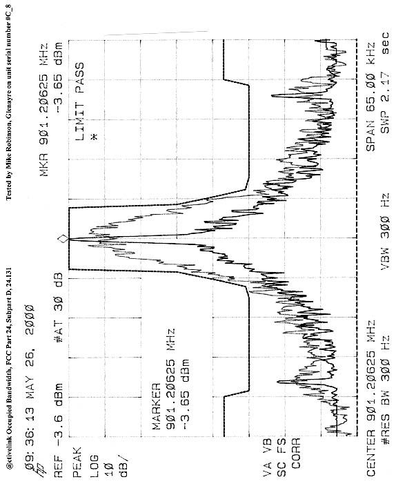
Wireless Products 2101 Tasman Drive Santa Cl ara, CA 95054 USA tel 408-653-1555 fax 408-653-1543 Occupied Bandwidth: FCC Part 24, Subpart D, 24.133 FCC Part 90, Subpart I, 90.210 • Test Conditions The @ctivelink module was positioned standing on its right side. This position was determined to have the worst case emissions. The HP spectrum analyzer was configured for a resolution bandwidth of 300Hz and a span of 65kHz. All spectrum analyzer measurements were made using the Peak detector function. The spectrum analyzer reference level was set to the unmodulated (carrier only) peak power level. This was done by starting a test routine on the module that generates carrier only. This reference trace was stored in the memory of the spectrum analyzer. Next, internal test code was started in the module that continuously modulates the transmitter with pseudo-random data. An overlay of the carrier only spectrum, the occupied BW, and the FCC mask was plotted from the spectrum analyzer. • List of Test Equipment 1. Spectrum Analyzer, Hewlett Packard, Model No. 8591E, S/N 3346A02282. Calibration date: March 18, 2000. Calibration due date: March 18, 2001. • Diagram of Test Setup RF INPUT @ctive Link under test HP8591E Spectrum Analyzer
Test Report
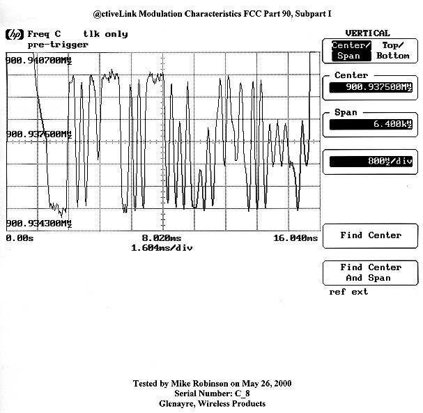
Wireless Products 2101 Tasman Drive Santa Cl ara, CA 95054 USA tel 408-653-1555 fax 408-653-1543 Modulation Characteristics: FCC Part 24, Subpart D, 24.131 FCC Part 90, Subpart I, 90.211 • Test Conditions The @ctivelink module was positioned standing on its right side. This position was determined to have the worst case emissions. The HP modulation domain analyzer was configured to have a span of 6.4kHz. An acknowledgement transmission, which is representative of all transmissions from the module, was captured on the modulation domain analyzer. • List of Test Equipment 1. Modulation Domain Analyzer, Hewlett Packard, Model No. 53310A, S/N KR93200189. Calibration date: April 27, 2000. Calibration due date: April 27, 2001. • Diagram of Test Setup RF INPUT @ctiveLink under test
Test Report
Wireless Products 2101 Tasman Drive Santa Cl ara, CA 95054 USA tel 408-653-1555 fax 408-653-1543 Frequency Variation vs. Temperature: FCC Part 24, Subpart D, 24.135 FCC Part 90, Subpart I, 90.213 • Test Conditions The @ctivelink module was positioned standing on its bottom, 68-pin-connector edge inside of a Thermotron temperature test chamber. The module was programmed such that all transmissions from the module were unmodulated (carrier only) in order to facilitate accurate measurements of the carrier frequency. The HP modulation domain analyzer was configured to have a span of 6.4kHz. An acknowledgement transmission, which is representative of all transmissions from the module, was captured on the modulation domain analyzer at temperatures between –30 and +50°C in 5°C steps. The carrier frequency deviation was measured from the modulation domain analyzer capture. • List of Test Equipment 1. Modulation Domain Analyzer, Hewlett Packard, Model No. 53310A, S/N KR93200189. Calibration date: April 27, 2000. Calibration due date: April 27, 2001. 2. Temperature Test Chamber, Thermotron, Model No. S8C, S/N 23834. Calibration date: November 10, 1999. Calibration due date: June 1, 2000. • Diagram of Test Setup RF INPUT @ctiveLink under test
Test Report
Glenayre Electronics, Inc. ActiveLink UnitSeiral Number C-8 ActiveLink Temperature Test Results TempPPMHz dev -30-0.20-181 -25-0.02-18 -20-0.42-375 -15-0.24-212 -10-0.25-225 -5-0.35-318 0-0.33-293 5-0.11-100 10-0.26-231 15-0.35-318 20-0.21-187 25-0.24-218 30-0.29-262 35-0.35-318 40-0.35-318 45-0.25-225 50-0.26-237 Frequency Variation vs Temperature -0.50 -0.40 -0.30 -0.20 -0.10 0.00 0.10 0.20 0.30 0.40 0.50 -35-30-25-20-15-10-50510152025303540455055 Temperature (Celsius) PPM deviation from 901.20625 MHz Tested by Julie D'AddiecoFCC Part 24, Subpart D, Section 24.135 May 30, 2000
Test Report
Wireless Products 2101 Tasman Drive Santa Cl ara, CA 95054 USA tel 408-653-1555 fax 408-567-1069 Description of the Duty Cycle for the @ctivelink Wireless Messaging Module The worst case duty cycle for the @ctivelink module transmitter occurs on a collapse of 1 when it is sending messages from the module to the infrastructure. For this calculation, assume infinite messages are queued in the module, each message is the maximum length allowed (2000 characters), and the back channel is running at its slowest speed (800 bps). The ReFLEX protocol is timed on frames, each of which is 1.875 seconds long. The sequence for transmitting a message from the module is shown in the following table. Also shown are transmitter on times and elapsed ti me. FrameEventTransmitter on timeElapsed time 1Module signals request to transmit to system 0.17051.875 2Request goes to system controller and is scheduled 01.875 3Unusable frame01.875 4Grant for data unit is sent to Module01.875 5Module sends first data unit (100 characters) to system 1.8751.875 6Data unit goes to system controller and next data unit is scheduled 01.875 7Unusable frame01.875 8Grant for next data unit is sent to Module01.875 9Module sends data unit to system1.8751.875 10-81steps 6-9 repeat unit entire message is trans mi tted (18 more data units for a total of 20) 18 X 1.87572 X 1.875 82Last data unit goes to system controller and end of transmission is scheduled 01.875 83Unusable frame01.875 84End of transmission is sent to module01.875 85Ack to end of transmission is transmitted from module to system 0.17051.875 Totals 37.841 seconds159.375 seconds Thus, the maximum duty cycle for the @ctivelink is 37.841/ 159.375 = 23.74 % Note this is not achievable in a real system due to delays in computing and traffic delays, and is only a theoretical maximum based on the protocol.
Test Report
Report No: FC00-052 Page 1 of 25 GLENAYRE ELECTRONICS, INC. TEST REPORT FOR THE WIRELESS MESSAGING MODULE, @CTIVELINK (TRANSMITTER PORTION ONLY) FCC PARTS 2 AND 24 COMPLIANCE DATE OF ISSUE: JUNE 13, 2000 PREPARED FOR: Glenayre Electronics, Inc. 2101 Tasman Drive Santa Clara, CA 95054 P.O. No: L7683 W.O. No: 74365 PREPARED BY: Joyce Walker CKC Laboratories, Inc. 5473A Clouds Rest Mariposa, CA 95338 Date of test: May 8-17, June 5 & 6, 2000 Report No: FC00-052 DOCUMENTATION CONTROL: _____________________________ Tracy Phillips Documentation Control Supervisor CKC Laboratories, Inc. APPROVED BY: _____________________________ Dennis Ward Director of Laboratories CKC Laboratories, Inc. This report contains a total of 25 pages and may be reproduced in full only. Partial reproduction may only be done with the written consent of CKC Laboratories, Inc. Report No: FC00-052 Page 2 of 25 TABLE OF CONTENTS FOR CERTIFICATION TEST REPORT Administrative Information .............................................................................................................3 Summary Of Results........................................................................................................................4 Equipment Under Test (EUT) Description......................................................................................4 Measurement Uncertainty................................................................................................................4 Peripheral Devices ...........................................................................................................................4 2.1033(c)(4) – Type(s) of Emissions ...............................................................................................5 2.1033(c)(5) – Frequency Range .....................................................................................................5 2.1033(c)(6) – Range of Operating Power ......................................................................................5 2.1033(c)(7) – Maximum Power Rating..........................................................................................5 2.1033(c)(8) – DC Voltages ............................................................................................................5 2.1033(c)(9) – Tune-Up Procedure .................................................................................................5 2.1033(c)(10) – Frequency Stabilization, Modulation, & Spurious Radiation ...............................5 2.1033(c)(13) – Description of Modulation ....................................................................................5 2.1033(c)(14)/2.1046/24.132 - RF Power Output ...........................................................................6 2.1033(c)(14)/2.1047(a)/24.131 - Modulation Characteristics - Audio Frequency Response ......18 2.1033(c)(14)/2.1047(b)/24.131 - Modulation Characteristics – Modulation Limiting Response18 2.1033(c)(14)/2.1049/24.131 - Occupied Bandwidth....................................................................18 2.1033(c)(14)/2.1051/N/A - Spurious Emissions at Antenna Terminal ........................................18 2.1033(c)(14)/2.1053/24.133 - Field Strength of Spurious Radiation...........................................18 2.1033(c)(14)/2.1055/24.135/24.135 - Frequency Stability ..........................................................25 Report No: FC00-052 Page 3 of 25 ADMINISTRATIVE INFORMATION DATE OF TEST: Date of test: May 8, 2000 PURPOSE OF TEST: To demonstrate the compliance of the Wireless Messaging Module, @ctiveLink with the requirements for devices under FCC Parts 2 and 24. MANUFACTURER: Glenayre Electronics, Inc. REPRESENTATIVE: Louie Sanguinetti TEST LOCATION: CKC Laboratories, Inc. 1653 Los Viboras Road Hollister, CA 95023 TEST PERSONNEL: Art Rice TEST METHOD: FCC Part 2 and Part 24 EQUIPMENT UNDER TEST:Wireless Messaging Module Manuf:Glenayre Electronics, Inc. Model:@ctiveLink Serial:C8 FCC ID:K3N7000 (pending) Report No: FC00-052 Page 4 of 25 SUMMARY OF RESULTS The Wireless Messaging Module, @ctiveLink, was tested in accordance with FCC Part 2 and Part 24 for compliance with the transmitter characteristic requirements of the FCC Rules. As received, the above equipment was found to be fully compliant with the limits of FCC Parts 2 and 24. EQUIPMENT UNDER TEST (EUT) DESCRIPTION The Wireless Messaging Module, @ctiveLink for the Handspring Visor PDA. MEASUREMENT UNCERTAINTY Associated with data in this report is a±4dB measurement uncertainty. PERIPHERAL DEVICES The EUT was tested with the following peripheral devices: Personal Data Assistant Manuf:Handspring Model:Visor Serial:WAI 0863 (asset #) FCC ID: DoC Laptop PC Manuf:Toshiba Model:PA1205U X Serial:12424214 FCC ID: CJ6UK454 AC adapter for PC Manuf:Toshiba Model:PA2431U Serial:9505 FCC ID: none Docking station Manuf:Handspring Model:Serial Cradle Serial:3003E FCC ID: DoC Report No: FC00-052 Page 5 of 25 2.1033(c)(4) – Type(s) of Emissions 10K0F1D 2.1033(c)(5) – Frequency Range 901 – 902 MHz 2.1033(c)(6) –Range of Operating Power The operating RF output power (ERP) is 2.80 watts. The output power is fixed. There is no means provided for variation of the operating power. 2.1033(c)(7) – Maximum Power Rating The maximum power rating as defined in Part 24.132(a) is 7 watts E.R.P. The Wireless Messaging Module, @ctiveLink has a maximum power rating of 2.80 watts. 2.1033(c)(8) - DC Voltages The transmitter in the @ctiveLink is powered by a 3.6V NiCad battery internal to the unit. The NiCad battery supplies a DC voltage of 3.6V and a current of 600mA to the final RF power amplifier stage. 2.1033(c)(9) – Tune-Up Procedure There is no tune-up procedure for the output power as it is fixed to the maximum output power supplied by the final RF power amplifier stage. There is no means provided for variation of the operating power. 2.1033(c)(10) – Frequency Stabilization, Modulation, & Spurious Radiation This section has…
Text truncated - open the document above for the full version.
Test Report
Report No: FC00-052A Page 1 of 25 ADDENDUM TO GLENAYRE ELECTRONICS, INC. TEST REPORT FC00-052 FOR THE WIRELESS MESSAGING MODULE, @CTIVELINK (TRANSMITTER PORTION ONLY) FCC PARTS 2 AND 24 COMPLIANCE DATE OF ISSUE: JUNE 22, 2000 PREPARED FOR: Glenayre Electronics, Inc. 2101 Tasman Drive Santa Clara, CA 95054 P.O. No: L7683 W.O. No: 74365 PREPARED BY: Joyce Walker CKC Laboratories, Inc. 5473A Clouds Rest Mariposa, CA 95338 Date of test: May 8-17, June 5 & 6, 2000 Report No: FC00-052A DOCUMENTATION CONTROL: _____________________________ Tracy Phillips Documentation Control Supervisor CKC Laboratories, Inc. APPROVED BY: _____________________________ Dennis Ward Director of Laboratories CKC Laboratories, Inc. This report contains a total of 25 pages and may be reproduced in full only. Partial reproduction may only be done with the written consent of CKC Laboratories, Inc. Report No: FC00-052A Page 2 of 25 TABLE OF CONTENTS FOR CERTIFICATION TEST REPORT Administrative Information .............................................................................................................3 Summary Of Results........................................................................................................................4 Equipment Under Test (EUT) Description......................................................................................4 Measurement Uncertainty................................................................................................................4 Periphe…
Text truncated - open the document above for the full version.
Contact Information
Applicant
Louie Sanguinetti(Director of Engineering)
Technical Contact
CKC Laboratories, Inc.Tracy Phillips
[email protected]1-800-500-4362
5473A Clouds Rest · Mariposa, California · United States
Non-Technical Contact
CKC Laboratories, Inc.Joyce Walker
[email protected]1-800-500-4362
Test Firm
CKC Laboratories, Inc.Steve Behm
Technical Specifications
| # | Rule Parts | Frequency Range | Power Output | Emission | Tolerance |
|---|---|---|---|---|---|
| 2 | 9 | 896 MHz - 902 MHz | 1.1 W | 10K0F1D | 0.42 ppm |
Other Applications from Glenayre Electronics Inc.
K3N8000
Dec 27, 2001Reflex Location Device, @ctiveFind
Equipment Class
PCB - PCS Licensed Transmitter
K3N6000
Feb 21, 2000AccessLinkII 2-Way Pager
Equipment Class
PCT - PCS Licensed Transmitter worn on body
K3N5000
Aug 19, 1998PCT - PCS Licensed Transmitter worn on body
Equipment Class
PCT - PCS Licensed Transmitter worn on bodyK3N3000
Mar 17, 1996Two-Way Pager
Equipment Class
JBP - Part 15 Class B Computing Device PeripheralK3N-ACCESSCARD-GX
Mar 16, 1994PCMCIA Paging Receiver
Equipment Class
CXX - Communications Rcvr for use w/ licensed Tx and CBs