K68ND1579AND1579-P-3 Short Range Datasonde
Radiodetection Ltd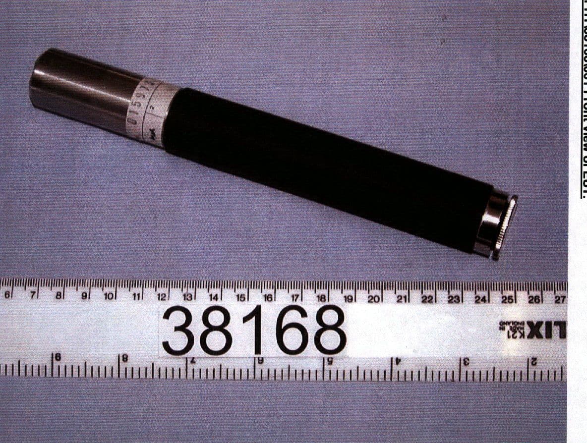
Click to zoom
Application Details
- Equipment Class
- DCD - Part 15 Low Power Transmitter Below 1705 kHz
- Date of Grant
- Apr 02, 2000
- Application Purpose
- Original Equipment
- Date of Application
- Mar 21, 2000
- Equipment Note
- ND1579-P-3 Short Range Datasonde
- Frequency Range
- 0.03300000 - 0.03300000
- Company
- Radiodetection Ltd
- Country
- United Kingdom
Documents & Files
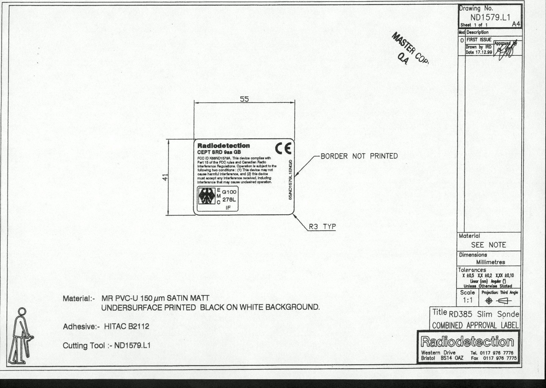
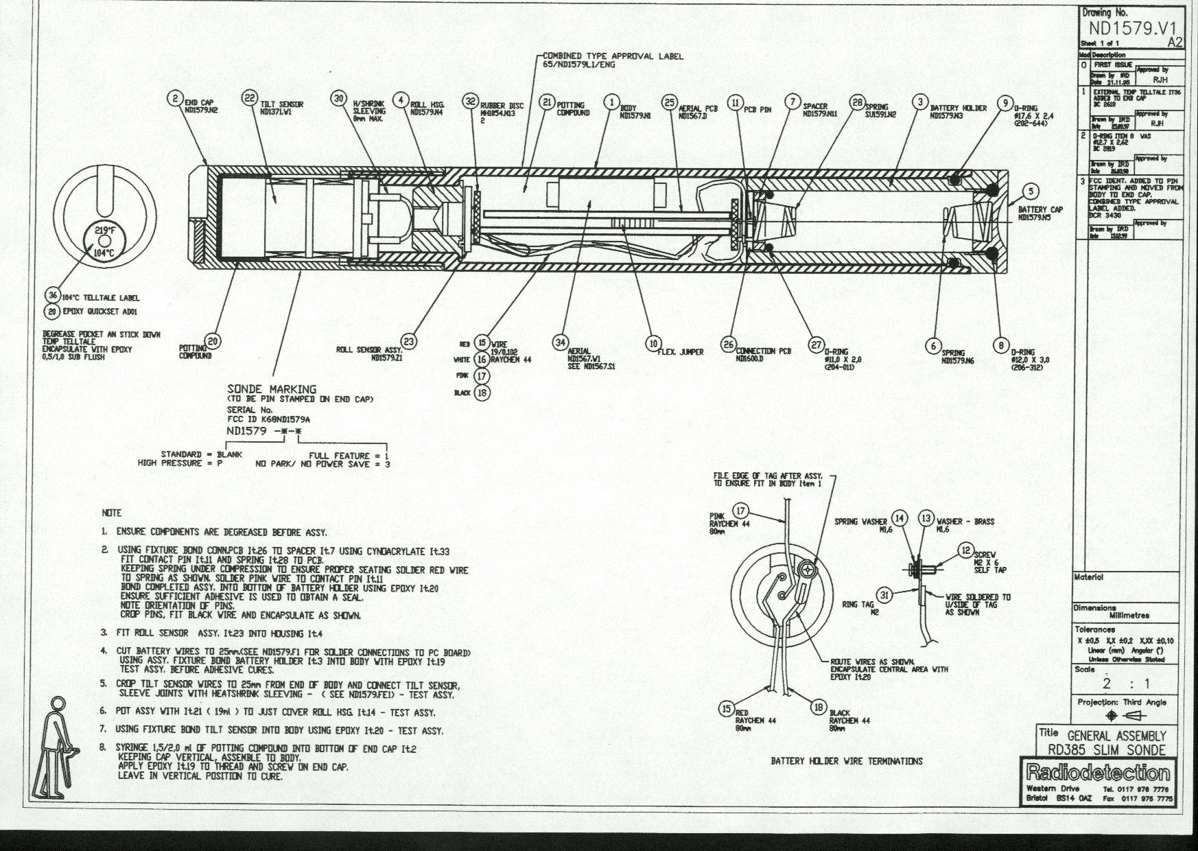
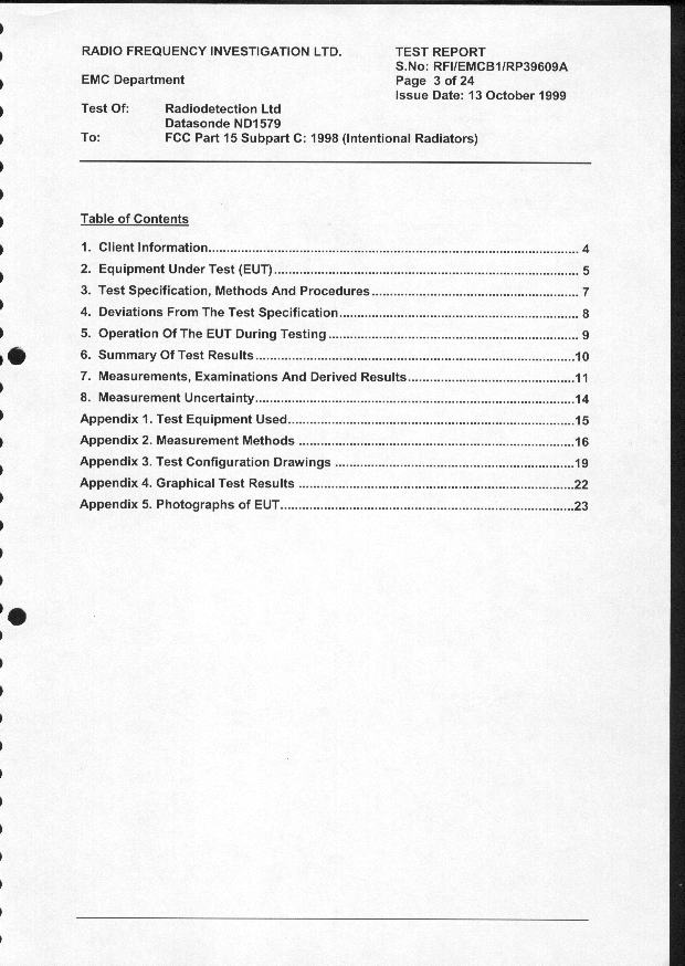
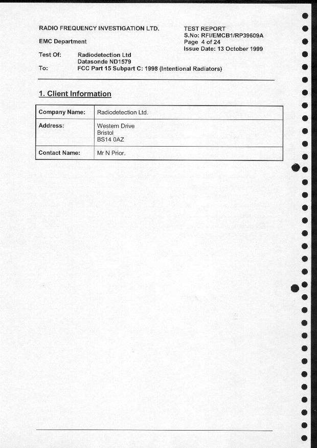
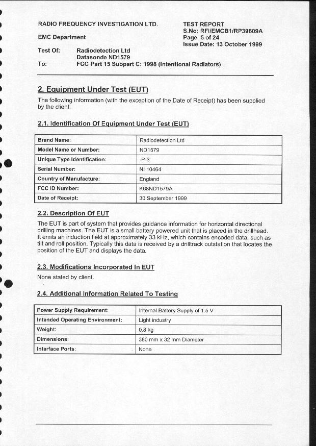
Document Text
Text extracted from the exhibit documents filed with the FCC. Open a document above to read the original.
Users Manual
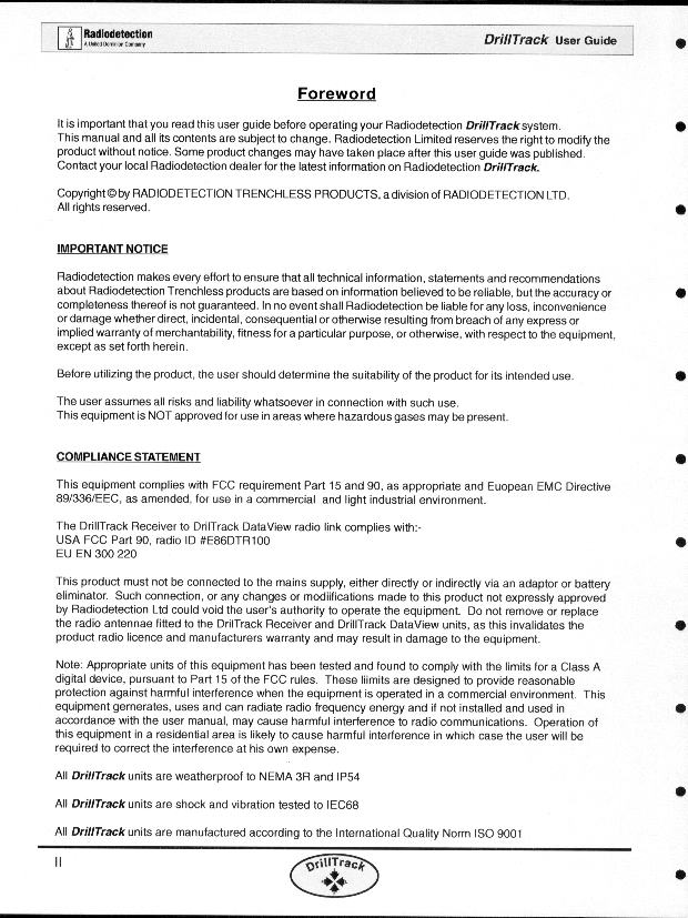
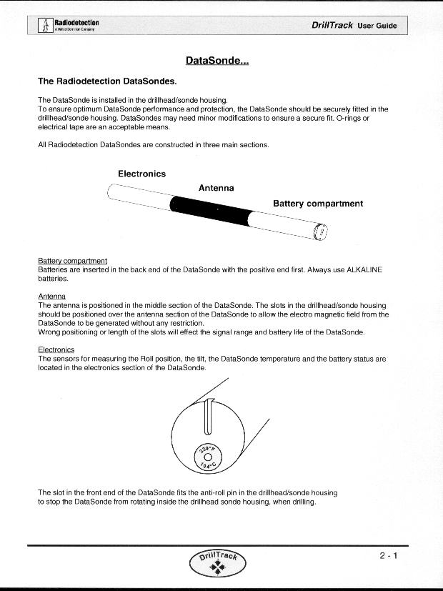
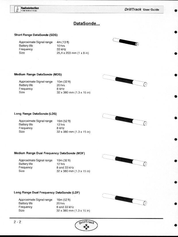
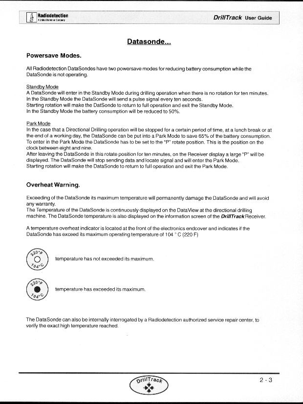
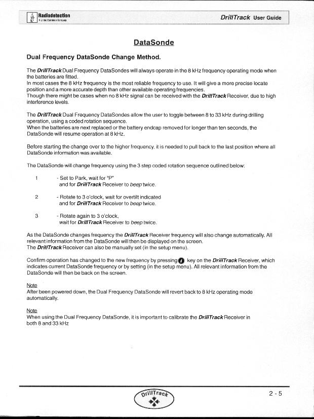
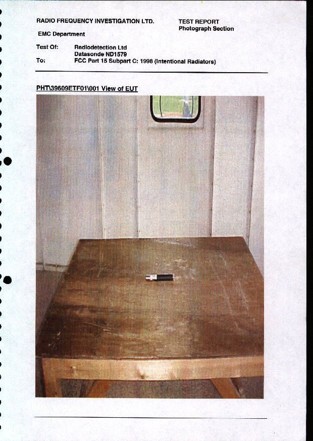
92639 14 March 2000 Copyright © 2000 Radiodetection Ltd., Western D rive, Bristol, BS14 0AZ Notice: Unauthorized disclosure or copying of this document or part thereof is prohibited Notes on Datasonde User Manual The Radiodetection ND1579 (Short Range or Slim) Datasonde is part of the Radiodetection Drilltrack system. The DrillTrack system is designed to provide guidance information for horizontal directional drill machines. The basic system consists of a datasonde, a DrillTrack Receiver and a DrillTrack DataView. The datasonde is mounted in the drilling machine drillhead and transmits information on its pitch, roll position, temperature and battery status to the DrillTrack Receiver. The information received by the DrillTrack Receiver is then communicated to the DataView by a separate radio link. There is no specific user manual for the DrillTrack datasondes. Instructions on using the datasonde are included in an overall DrillTrack system user manual. Relevant pages from the DrillTrack system user manual are submitted as exhibits in support of the application for FCC certification of the Radiodetection Short Range datasonde.
Block Diagram
File: 92584Ve r: /AI2-Feb-00 Copyright © Radiodetection Ltd., Western D rive, Bristol, BS14 0AZ. Notice: Unauthorized disclosure or copying of this document or any part thereof is prohibited.
Cover Letter(s)
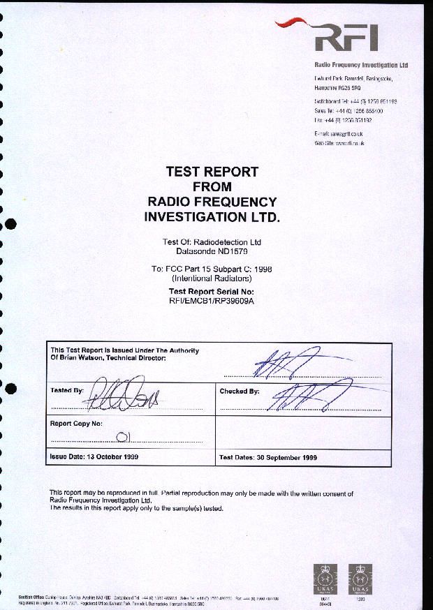
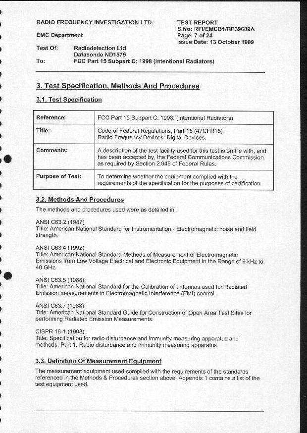
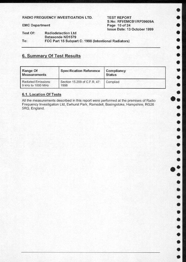
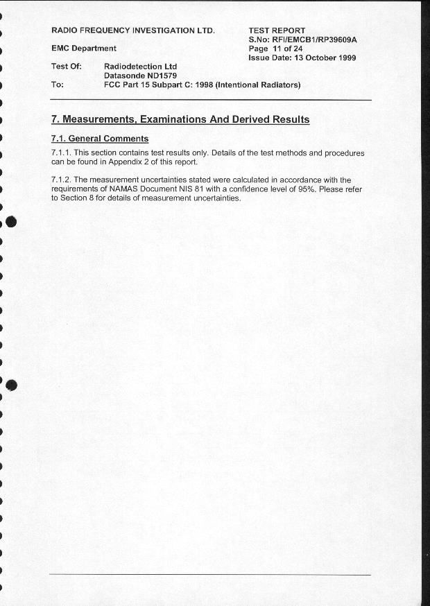
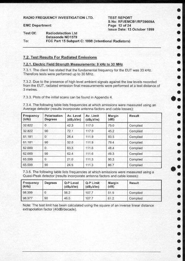
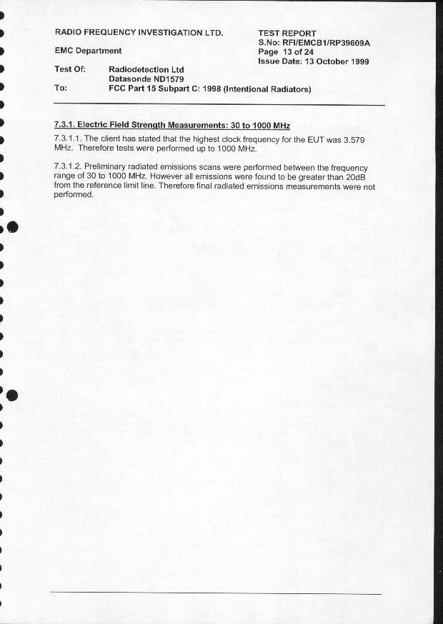
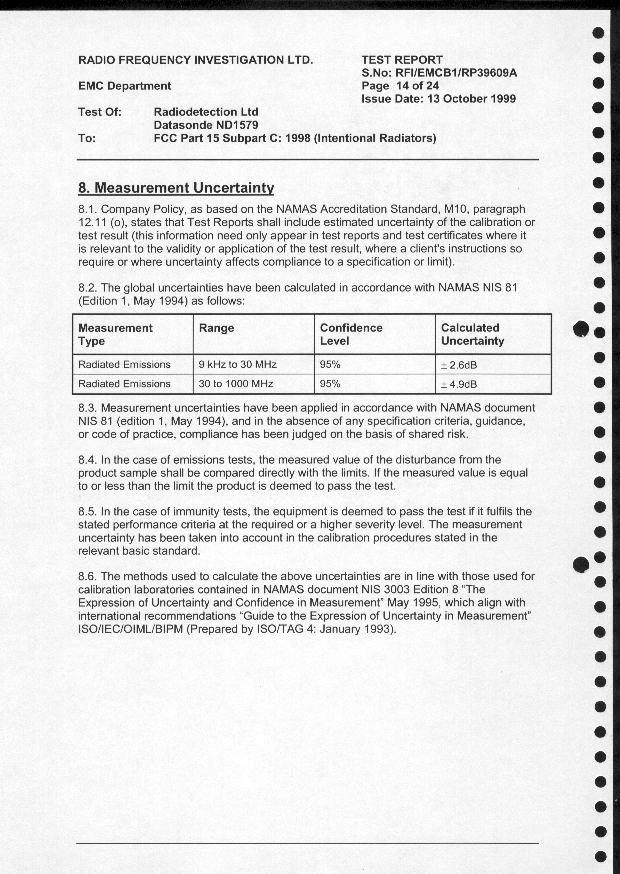
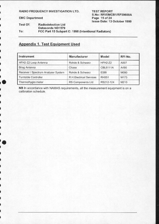
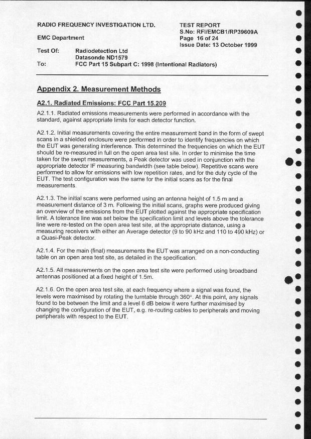
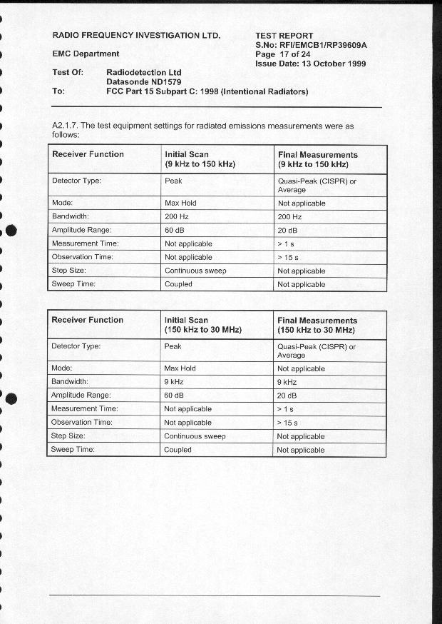
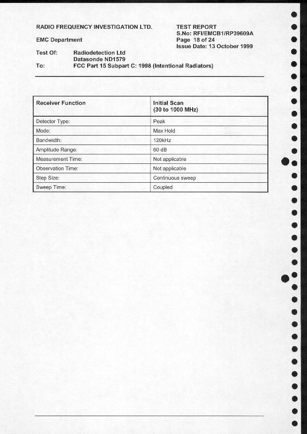
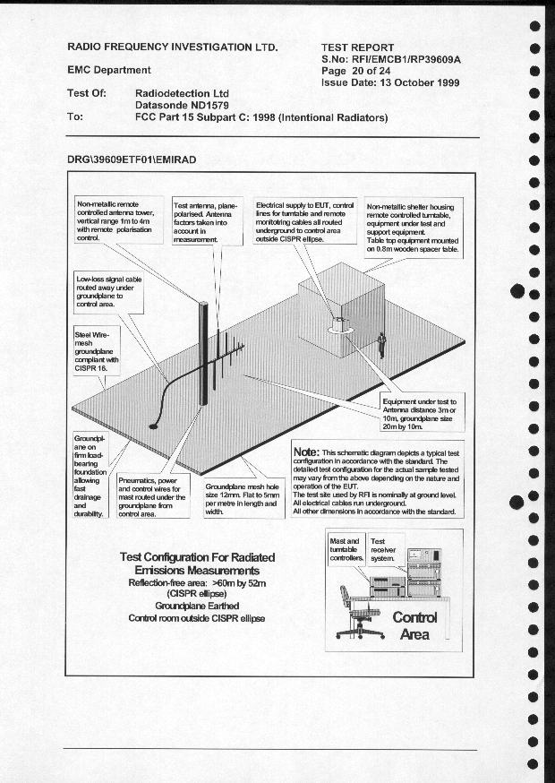
Federal Communications Commission Applications Processing Branch 7435 Oakland Mills Road Columbia MD 21046 USA 22 March 2000 Dear Sirs, FCC ID: K68ND1579A - Application for Certification of the Radiodetection Short Range Datasonde We wish to apply for certification of our Short Range Datasonde (part number ND1579-P-3). The datasonde, also know as a ‘Slim Sonde’, is part of our DrillTrack system, which is designed to provide guidance information for horizontal directional drill machines. The datasonde is mounted in the drilling machine drillhead and transmits information on its pitch, roll position, temperature and battery status to a DrillTrack receiver. The information is transmitted at 33 kHz. The datasonde has been successfully tested by Radio Frequency Investigation Ltd (RFI), a UK test house, in accordance with the requirements of FCC Part 15 Subpart C. The RFI test report (serial number RFI/EMCB1/RP39609A) is entitled ‘Test of: Radiodetection Ltd Datasonde ND1579’ and records the results of tests on a representative sample of our ND2099-P-3 product. Yours faithfully, Dr Roger Lee Principal Engineer (Approvals) For and on behalf of Radiodetection Ltd.
Cover Letter(s)
92656 21 March 2000 Page 1 of 3 Copyright © 2000 Radiodetection Ltd., Western D rive, Bristol, BS14 0AZ. Notice: Unauthorized disclosure or copying of this document or any part thereof is prohibited WESTERN DRIVE, BRISTOL BS14 0AZ, ENGLAND FCC ID: K68ND1579A - Application for Equipment Certification Request for Material to be Withheld from Public Inspection Introduction The Radiodetection Short Range (or Slim) Datasonde (part number ND1579-P-3) is part of the Radiodetection Drilltrack system. The DrillTrack system is designed to provide the operator of a horizontal directional drill machine with information on the drillhead. Request for Material to be Withheld from Public Inspection For the reasons presented below, it is requested that the information detailed below is withheld from public inspection for a period of five years from its submission to the FCC by Radiodetection. Identification of Confidential Information Confidential treatment is being sought for the following information concerning the Radiodetection ND1579-P-3 datasonde: - schematic circuit diagrams - internal photographs A detailed list of confidential items is presented in Appendix 1 Reason for Submission The information is submitted in support of an application for FCC certification of the ND1579-P-3 datasonde. Degree to which the Information is Confidential The information is confidential for commercial and financial reasons because Radiodetection has invested considerable design effort and expense in developing the datasonde and the system with which it works. Degree to which the Information concerns a Service subject to Competition The datasonde is part of a system is designed to provide the operator of a horizontal directional drill machine with information on the drillhead. The market for products such as these is highly competitive. The system is sold to customers such as public utilities and telecommunications companies. The USA is Radiodetection’s largest market. 92656 21 March 2000 Page 2 of 3 Copyright © 2000 Radiodetection Ltd., Western D rive, Bristol, BS14 0AZ. Notice: Unauthorized disclosure or copying of this document or any part thereof is prohibited Harm to Competitiveness Resulting from Disc losure of the Information Design and development costs make a significant contribution to the overall costs of our products and those of competitors. The products’ time-to-market depends to the time taken to complete the design phase. The disclosure of the information would give a competitor an unfair advantage by allowing it to reduce its design time and expenditure. Measures taken to Prevent Unauthorized Disclosure All Radiodetection designs are treated as ‘Company Confidential’. Design information is not released to third parties, other than those providing sub-contact production services to Radiodetection. Sub-contractors are subject to confidentiality agreements. Availability of the Information to the Public and Previous Disclosure to Third Parties The information submitted to the FCC is not available to the public or published by Radiodetection in its technical literature or handbooks. Products are sold only by Radiodetection and its own agents. There has been no previous disclosure to third parties, other than sub-contractors covered by confidentiality agreements. Justification for Period of Non-disclosure A non-disclosure period of five years is requested to ensure the any future disclosure of Radiodetection’s design will not take place until the datasonde and its design ideas are no longer of commercial value. For and on behalf of Radiodetection Limited, Roger Lee Principal Engineer (Approvals) 92656 21 March 2000 Page 3 of 3 Copyright © 2000 Radiodetection Ltd., Western D rive, Bristol, BS14 0AZ. Notice: Unauthorized disclosure or copying of this document or any part thereof is prohibited Appendix 1 List of Confidential Information DrawingItem ND1566.AMicro PCB Schematic Diagram ND1567.AOutput PCB Schematic Diagram ND1585.ARoll PCB Schematic Diagram PhotographND1579 Datasonde Internal View PhotographND1566 Micro PCB Top View PhotographND1566 Micro PCB Bottom View PhotographND1567 PS OP PCB Top View PhotographND1567 PS OP PCB Bottom View
Cover Letter(s)
93824 30 March 2000 Page 1 of 1 Copyright © 2000 Radiodetection Ltd., Western D rive, Bristol, BS14 0AZ. Notice: Unauthorized disclosure or copying of this document or any part thereof is prohibited WESTERN DRIVE, BRISTOL BS14 0AZ, ENGLAND FCC ID: K68ND1579A - Application for Equipment Certification Form 731 Confirmation Number: EA97115 Amendment to Request for Material to be Withheld from Public Inspection Introduction Radiodetection has requested that the internal photographs of its ND1579-P-3 datasonde are withheld from public inspection. The FCC has stated that it is unable to withhold the internal photographs from inspection because the information will be available publicly when the product is manufactured. Amendment to Request for Material to be Withheld from Public Inspection As a result of the FCC’s statement, Radiodetection withdraws its request that the internal photographs of the ND1579-P-3 be given confidential treatment. The request for confidential treatment of the schematic circuit diagrams is maintained. A revised detailed list of the confidential items is presented below: DrawingItem ND1566.AMicro PCB Schematic Diagram ND1567.AOutput PCB Schematic Diagram ND1585.ARoll PCB Schematic Diagram For and on behalf of Radiodetection Limited, Roger Lee Principal Engineer (Approvals)
Operational Description
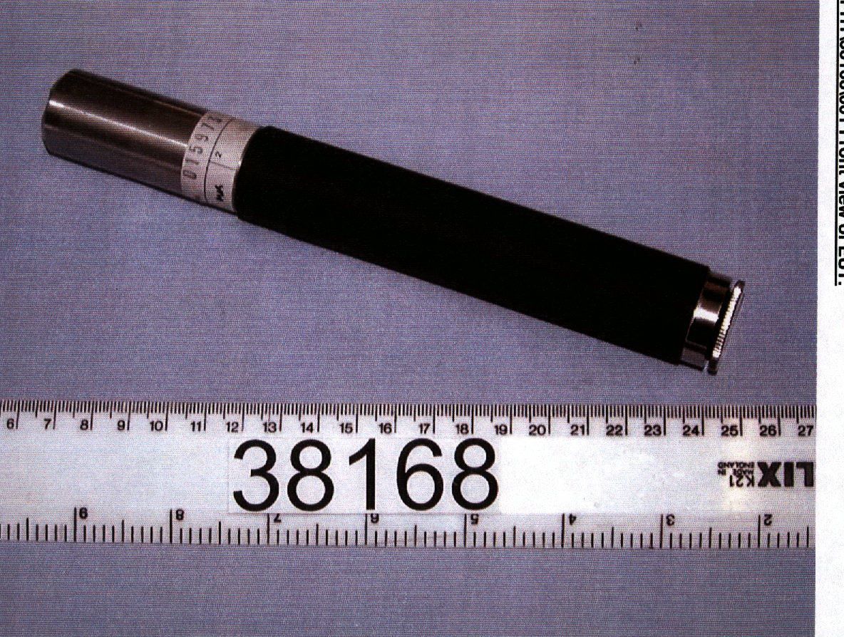
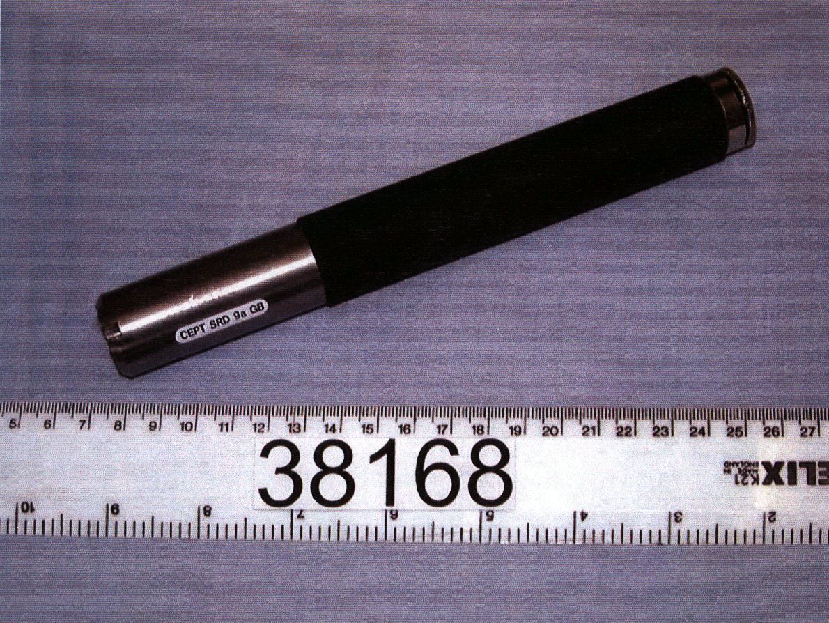
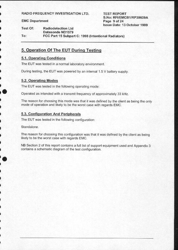
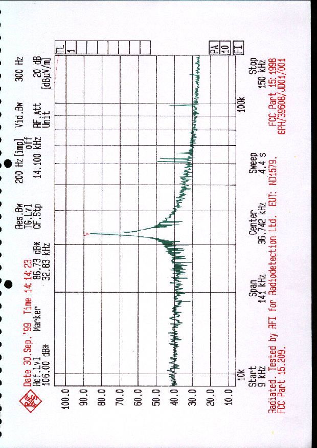
92884 23 March 2000 Page 1 of 4 Copyright © 2000 Radiodetection Ltd., Western Drive, Bristol, BS14 0AZ. Notice: Unauthorized disclosure or copying of this document or any part thereof is prohibited ND1579-P-3 Short Range Datasonde Technical and Operational Description FCC IDK68ND1579A Declaration of Equipment Characteristics TypeTransmitter Frequency Range33 kHz only Method of Carrier Frequency GenerationCrystal Channel SpacingWideband Class of Emission75H0K1D Type of ModulationAmplitude Modulation Signal Input LevelN/A Modulation Input ImpedanceN/A Modulation BandwidthN/A Coupling MethodsElectrical Number of Channels1 UtilisationPortable Duplex operationNo AntennaIntegral Alternative AntennaNo Operating temperature range -20 ° C to +55 ° C Transmitter Rated Output75.0 dB V/m C.W. 2nd Harmonic output25.0 dB V/m Voltage supply range1.275 to 1.5 V DC Composition of EquipmentSingle Unit 92884 23 March 2000 Page 2 of 4 Copyright © 2000 Radiodetection Ltd., Western Drive, Bristol, BS14 0AZ. Notice: Unauthorized disclosure or copying of this document or any part thereof is prohibited Radiodetection Short Range Datasonde Introduction The Radiodetection Short Range (or Slim) Datasonde (part no. ND1579-P-3) is part of the Radiodetection Drilltrack system. The DrillTrack system is designed to provide the operator of a horizontal directional drill machine with information on the drillhead. The basic system consists of a Datasonde, a DrillTrack Receiver and a DrillTrack DataView. The datasonde is mounted in the drilling machine drillhead and transmits information on its pitch, roll position, temperature and battery status to the DrillTrack Receiver. The information received by the DrillTrack Receiver is then relayed to the DataView by a separate radio link. The Short Range Datasonde transmits at 33 kHz. Overview The datasonde is a cylindrical device (203 mm long and 25.4 mm diameter) designed to fit into a cavity within a drillhead. It has a stainless steel and a plastic section. The plastic section to allows the datasonde to transmit. A block diagram of the datasonde is presented below: The datasonde is microprocessor-controlled and powered by an AA-cell alkaline battery. It has two main circuit boards: the ND1566 Micro Board and the ND1567 Output (or P/S O/P)Board. Sensors measure the temperature, roll position and tilt angle of the datasonde and the state of the battery powering the unit. The sensor outputs are fed to the microprocessor. This information is interpreted by the microprocessor and encoded. The encoded information is then passed to a modulator and driver circuit which produces a signal to drive the datasonde antenna. The antenna is a cylindrical coil with a ferrite core. It is mounted within the plastic section of the datasonde case. Battery State Sensor Temperature Sensor Processor Roll Sensor Tilt Sensor Antenna Driver Modulator Antenna 33 kHz 92884 23 March 2000 Page 3 of 4 Copyright © 2000 Radiodetection Ltd., Western Drive, Bristol, BS14 0AZ. Notice: Unauthorized disclosure or copying of this document or any part thereof is prohibited Modes of Operation While a datasonde is turning in a drillhead, it continuously transmits coded information. If the datasonde stops rotating for more than 10 minutes, it enters a ‘Standby’ mode. In this mode, battery consumption is reduced by 50% and a pulsed signal is transmitted every ten seconds. If the datasonde begins rotating again, it automatically reverts to its normal transmission mode. If a datasonde is to be left for some time, it can be switched to a ‘Park’ mode which reduces battery consumption by 65%. This is achieved monitoring the rotation position of the datasonde with a DrillTrack receiver, rotating the datasonde until the receiver indicates that the datasonde is in a special ‘Park’ position and leaving the datasonde for ten minutes. When in Park mode, the datasonde does not transmit but will revert to its normal mode as soon as rotation recommences. Transmission Data The output from the datasonde is an amplitude-modulated 33 kHz signal. Information is transmitted as a series of 10-bit words, each consisting of a start bit, seven data bits, a stop bit and an even parity bit. The data transmission rate is 75 baud. The sequence of data words depends on whether the datasonde is normal mode, entering park mode or is overheating. Within each word sequence, roll and tilt information is repeated frequently and interleaved with information on the datasonde status. When the datasonde is in normal mode or is over-temperature, a continuous series of data words is transmitted. In standby mode, the datasonde transmits a carrier wave pulse at approximately ten-second intervals. When the datasonde is entering park mode (parking), a parking sequence is transmitted for a few minutes and then all transmissions cease. The three datasonde word sequences are detailed on page 3. 92884 23 March 2000 Page 4 of 4 Copyright © 2000 Radiodetection Ltd., Western Drive, Bristol, BS14 0AZ. Notice: Unauthorized disclosure or copying of this document or any part thereof is prohibited Datasonde Status Data WordNormal ModeParkingOver-temperature 0RollRollRoll 1Datasonde TypeConfigurationConfiguration 2RollParkingRoll 3Low TiltLow TiltOver-temperature 4RollRollDatasonde Type 5High TiltHigh TiltOver-temperature 6RollParking 7Battery LevelBattery Level 8RollRoll 9TemperatureLow Tilt 10RollParking 11Low TiltHigh Tilt 12RollRoll 13High TiltTemperature 14RollParking 15ConfigurationDatasonde Type 16RollError/Status 17Steering 18Error/Status Table showing the Short Range Datasonde Word Sequences
Contact Information
Applicant
Andrew Brown(Principal Engineer)
Technical Contact
Radiodetection LtdRoger Lee
[email protected]00 44 117 988 6336
Western Drive · Bristol · United Kingdom
Non-Technical Contact
Radiodetection LtdRoger Lee
[email protected]00 44 117 988 6336
Test Firm
RFI Global Services Ltd.Allan Hume
Technical Specifications
| # | Rule Parts | Frequency Range | Power Output |
|---|---|---|---|
| 1 | 15C | 0.033 MHz - 0.033 MHz | - |
Other Applications from Radiodetection Ltd
K68AA2614
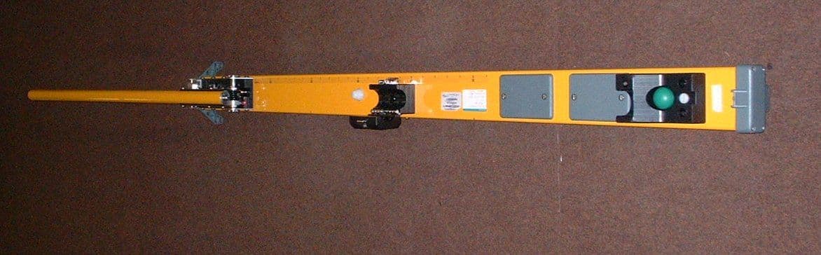
Nov 19, 200220ft Vector Bar type 10/AA 2614
Equipment Class
DSC - Part 15 Security/Remote Control Transmitter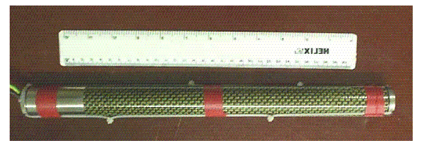
K68ND2585
Jul 08, 200210/ND2585 Wireline DataSonde
Equipment Class
DCD - Part 15 Low Power Transmitter Below 1705 kHz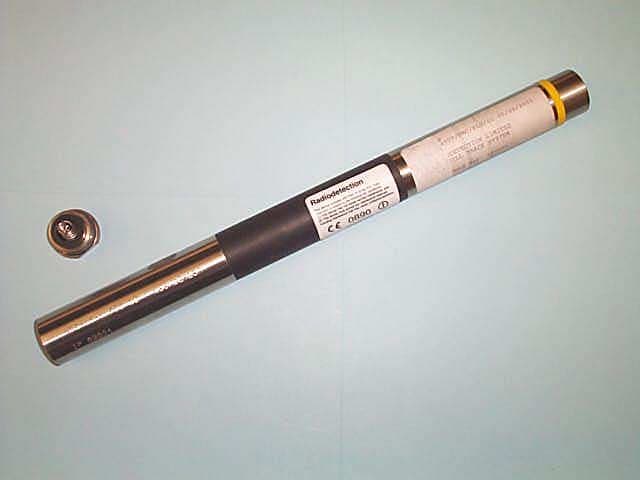
K68ND241A
Jun 21, 2001Low Frequency Drill Location Device
Equipment Class
DCD - Part 15 Low Power Transmitter Below 1705 kHz
K68ND241B
Jun 21, 2001Low Frequency Drill Location Device
Equipment Class
DCD - Part 15 Low Power Transmitter Below 1705 kHz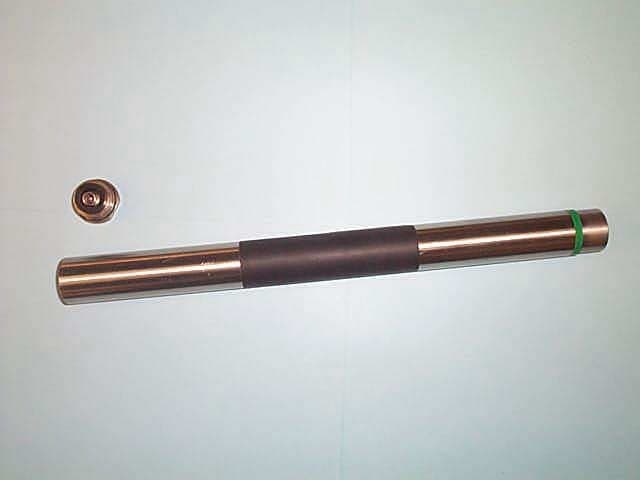
K68ND241C
Jun 21, 2001Low Frequency Drill Location Device
Equipment Class
DCD - Part 15 Low Power Transmitter Below 1705 kHz