K6M-DUALMWDUAL MIKE
Midland Europe srl
Click to zoom
Application Details
- Equipment Class
- DTS - Digital Transmission System
- Date of Grant
- Mar 09, 2020
- Application Purpose
- Original Equipment
- Date of Application
- Mar 09, 2020
- Equipment Note
- DUAL MIKE
- Frequency Range
- 2402.00000000 - 2480.00000000
- Company
- Midland Europe srl
- Country
- Italy
Documents & Files
Document Text
Text extracted from the exhibit documents filed with the FCC. Open a document above to read the original.
Users Manual
EN PTT CBTALK Push and talk into CBTalk CHANGE A CHANNEL ON CBTALK Channel down Channel up LEDLIGHT RING Turning ON: Blue led 3 sec. Turning OFF: Red led 3 sec. Pairing: Red and blue leds alternated Smartphone paired to Dual Mike: Blue led blinking Smartphone’s pairing not successful: red led blinking Default color: Steady blue (it will be set through the CBTalk APP) Incoming call: Steady white Low battery: blinking red PTT CB pressed: Steady yellow Download the CBTalk APP Android/iOs DUAL MIKE WITH CBTALK APP CB MICROPHONE Per scaricare il manuale completo e per informazioni sulla garanzia visitate il sito www.midlandeuro- pe.com • To download the complete user manual and for information about the warranty please visit www.midlandeurope.com • Zum Herunterladen der gesamten Anleitung und allen Informationen über die Garantie der Artikel, besuchen Sie bitte unsere www.midlandeurope.com • Para descargar el ma- nual completo y mayor información sobre la garantía, visite la web www.midland.es • Pour télécharger le manuel d’utilisation complet et des informations sur la garantie, s’il vous plaît visitez le site www.midlandeurope.com • Para fazer download do manual de utilizador e de informações sobre a garan- tia, por favor visite o site www.midlandeurope.com To download the complete user manual and for information about the warranty please visit www.midlandeurope.com QUICK GUIDE Prodotto o importato da: CTE INTERNATIONAL srl Via. R.Sevardi 7 42124 Reggio Emilia - Italia. Prima dell’uso leggere attentamente le istruzioni. Produced or imported by: CTE INTERNATIONAL srl Via. R.Sevardi 7 42124 Reggio Emilia - Italy. Read the instructions carefully before installation and use. Vertrieb durch: ALAN ELECTRONICS GmbH Daimlerstraße 1K - D-63303 Dreieich Deutschland. Vor Benutzung Bedienungsanleitung beachten. Importado por: MIDLAND IBERIA, SA C/Cobalt, 48 - 08940 Cornellà de Llobregat, Barcelona - España. Antes de utilizar, lea atentamente el manual de uso. Importé par: ALAN FRANCE S.A.R.L. 5, Rue Ferrie, Zac les Portes du Vexin 95300 Ennery - France. Avant l’utilisation, lire les instructions. 3 sec. 123 4 5 6 7 8 11 12 10 9 AL-DUAL 12V 3 sec. 3 sec. 3 sec. VOL+VOL- Device A DualMike_xxx Device B 3 sec. 13 DUALMIKE OVERVIEW GETTING STARTED Remove the standard microphone supplied with your transceiver and plug-in DUALMIKE AL-DUAL Cod. C1403 (optional) POWER ON PTT CB Press and talk towards the microphone Yellow Light ring Power On Led steady blue 3 sec. POWER OFF Power O Led steady red 3 sec. USING DUAL MIKE WITH YOUR CB RADIO 1. Volume - 2. Led 3. Volume + (Power O - 3 sec.) 4. Emergency key (or customizable) 5. Channel up; Channel down (CBTalk) 6. Speaker 7. USB charging port/FW upgrade port 8. Light ring 9. PTT CB 10. PTT CBTalk (Power On - 3 sec.) 11. Pin connector: 4 Pin 48 (C1283) 4 Pin (C1283.01) 6 Pin (C1283.02) 12. USB charge only 13. DUAL MIKE is supplied with a metallic plate for magnetic fi xing of the microphone. To use it remove the plastic support fi xed with a screw. USING DUAL MIKE WITH SMARTPHONES PAIRING 1 Pairing Red and blue leds alternately blink PRESS TOGETHER PAIRING 2 Connected (Telephone connected) Blue led blinking 3 sec. HAND-FREE PHONE CALLS AUDIO VOLUME To answer/to end a call White light ring To reject an incoming call White light ring To make a voice dial Bop (max vol. Beep)
Cover Letter(s)
CTE INTERNATIONAL S.R.L. Via Roberto Sevardi, 7 Mancasale Reggio Emilia, 42100 Italy [Nov. 28, 2019] Federal Communications Commission 445 12 th Street SW Washington, DC 20554 Subject: Limited Agency Agreement CTE INTERNATIONAL S.R.L. FCC ID: K6M-DUALMW To Whom It May Concern: We, CTE INTERNATIONAL S.R.L. hereby authorized Intertek Testing Services to act as our Agent for the purpose of preparing application for FCC ID number (K6M-DUALMW) under all applicable parts of the FCC rules and regulations. The effective date of this limited agency agreement is (2019-11-28). The Limited Agency Agreement expires until further notice, unless sooner terminated or extended by written notice to Intertek Testing Services and the Federal Communications Commission. This is to advise that we are in full compliance with the Anti-Drug Abuse Act. The applicant is not subject to a denial of federal benefits pursuant to Section 5301 of the Anti-Drug Act of 1988, 21 U.S.C. 862, and no party to the application is subject to a denial of federal benefits pursuant to that section. If you have any questions or comments, please do not hesitate to contact me. Sincerely, [Signature] [Rebecca Bardella] [Quality and Certification Manager]
Cover Letter(s)
CTE INTERNATIONAL S.R.L. Via Roberto Sevardi, 7 Mancasale Reggio Emilia, 42100 Italy Nov. 28, 2019 Federal Communication Commission Authorization and Evaluation Division FCC ID: K6M-DUALMW Re: Confidentiality Request Pursuant to Sections 0.457 and 0.459 of the Commission’s Rules, the applicant hereby requests confidential treatment of information applied this application as outlined below: 1: Block Diagram 2: Schematics 3: Operational Description The above materials contain trade secrets and proprietary information not customarily released to the public. The public disclosure of these matters might be harmful to the applicant and provide unjustified benefits to its competitors. The Applicant understands that pursuant to Rules 0.457, disclosure of this Application and all accompanying documentation will not be made before the date of the Grant for this application. Sincerely, CTE INTERNATIONAL S.R.L. Contact person: Rebecca Bardella Title: Quality and Certification Manager
External Photos
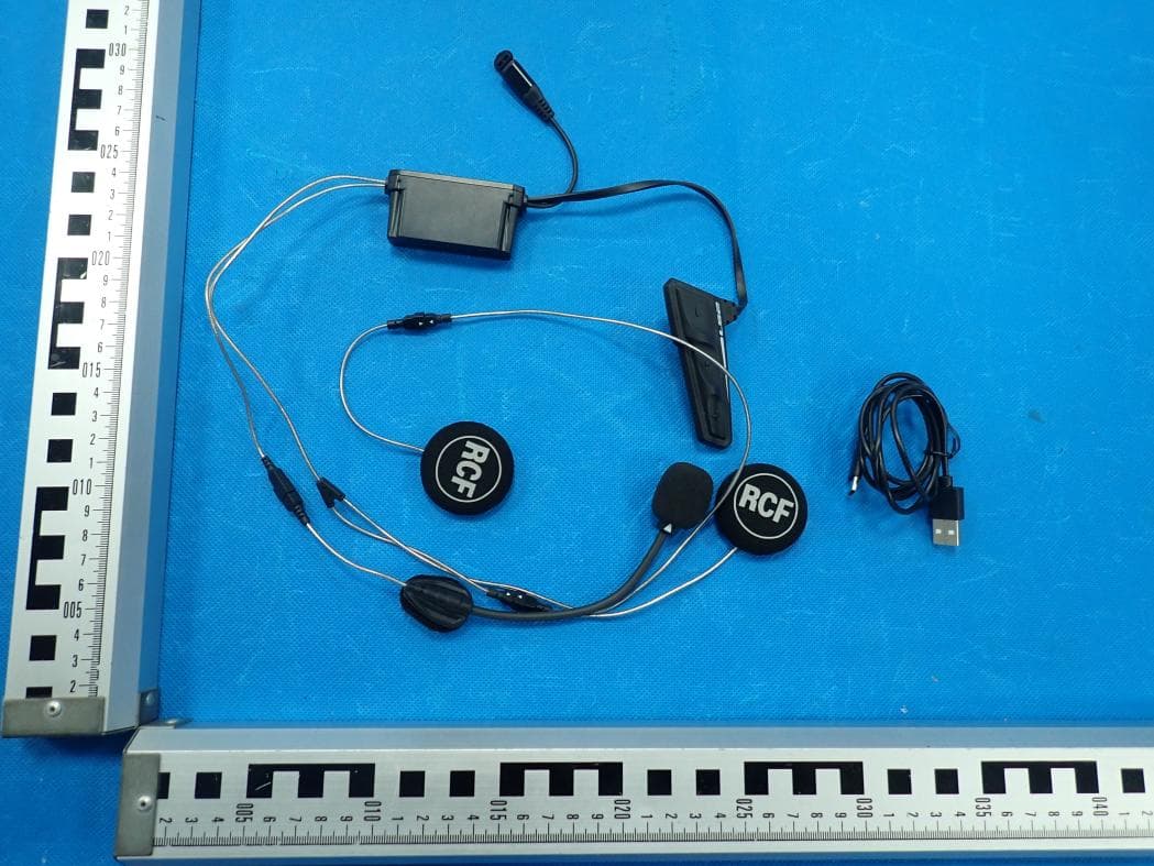
External Photos TOTAL VIEW OF EUT TOP VIEW OF EUT BOTTOM VIEW OF EUT FRONT VIEW OF EUT BACK VIEW OF EUT LEFT VIEW OF EUT RIGHT VIEW OF EUT VIEW OF EUT(PORT)-1 VIEW OF EUT(PORT)-2 VIEW OF EUT(PORT)-3
ID Label/Location Info
FCC ID and IC Label Location 5mm*20mm FCC ID: K6M-DUALMW IC: 23991-DUALMW HVIN: DUAL MIKE
Internal Photos
Internal Photos OPEN VIEW OF EUT VIEW OF BATTERY INTERNAL VIEW OF EUT-1 INTERNAL VIEW OF EUT-2 BT Antenna INTERNAL VIEW OF EUT-3
RF Exposure Info
RF EXPOSURE EVALUATION 1. PRODUCT INFORMATION Product Description DUAL MIKE Model Name DUAL MIKE FCC ID K6M-DUALMW 2. EVALUATION METHOD According to 447498 D01 General RF Exposure Guidance v05 The 1-g and 10-g SAR test exclusion thresholds for 100 MHz to 6 GHz at test separation distances ≤ 50 mm are determined by: [(max. power of channel, including tune-up tolerance, mW)/(min. test separation distance, mm)] ·[√f(GHz)] ≤ 3.0 for 1-g SAR and ≤ 7.5 for 10-g extremity SAR. Where f(GHz) is the RF channel transmit frequency in GHz Power and distance are rounded to the nearest mW and mm before calculation 3. CALCULATION BR/EDR: P t =7.165dBm=5.21mW The value of the Maximum output power P t is referred to the test report of the CFR47 §15.247. The result for RF exposure evaluation SAR=(5.21mW /5mm) .[√2.402(GHz)]= 1.62<3.0 for 1-g SAR and ≤ 7.5 for 10-g extremity SAR. BLE: P t =5.989dBm=3.97mW The value of the Maximum output power P t is referred to the test report of the CFR47 §15.247. The result for RF exposure evaluation SAR=(3.97mW /5mm) .[√2.402(GHz)]= 1.23<3.0 for 1-g SAR and ≤ 7.5 for 10-g extremity SAR. 4. CONCLUSION The SAR evaluation is not required.
Test Report
Page 1 of 49 FCC Test Report Report No.: AGC05067191001FE02 FCC ID : K6M-DUALMW APPLICATION PURPOSE : Original Equipment PRODUCT DESIGNATION : DUAL MIKE BRAND NAME : MIDLAND MODEL NAME : DUAL MIKE APPLICANT : CTE INTERNATIONAL S.R.L. DATE OF ISSUE : Nov. 26, 2019 STANDARD(S) : FCC Part 15.247 REPORT VERSION : V1.0 Attestation of Global Compliance (Shenzhen) Co., Ltd CAUTION: This report shall not be reproduced except in full without the written permission of the test laboratory and shall not be quoted out of context. Report No.: AGC05067191001FE02 Page 2 of 49 REPORT REVISE RECORD Report Version Revise Time Issued Date Valid Version Notes V1.0 / Nov. 26, 2019 Valid Initial Release Report No.: AGC05067191001FE02 Page 3 of 49 TABLE OF CONTENTS 1. VERIFICATION OF COMPLIANCE .............................................................................................................. 5 2. GENERAL INFORMATION .......................................................................................................................... 6 2.1. PRODUCT DESCRIPTION................................................................................................................... 6 2.2. TABLE OF CARRIER FREQUENCYS .................................................................................................. 6 2.3. RELATED SUBMITTAL(S)/GRANT(S) ................................................................................................. 7 2.4. TEST METHODOLOGY ....................................................................................................................... 7 2.5. SPECIAL ACCESSORIES .................................................................................................................... 7 2.6. EQUIPMENT MODIFICATIONS ........................................................................................................... 7 3. MEASUREMENT UNCERTAINTY ............................................................................................................... 8 4. DESCRIPTION OF TEST MODES ............................................................................................................... 9 5. SYSTEM TEST CONFIGURATION ............................................................................................................ 10 5.1. CONFIGURATION OF TESTED SYSTEM .......................................................................................... 10 5.2. EQUIPMENT USED IN TESTED SYSTEM ......................................................................................... 10 5.3. SUMMARY OF TEST RESULTS ........................................................................................................ 10 6. TEST FACILITY ......................................................................................................................................... 11 7. PEAK OUTPUT POWER ........................................................................................................................... 12 7.1. MEASUREMENT PROCEDURE ........................................................................................................ 12 7.2. TEST SET-UP (BLOCK DIAGRAM OF CONFIGURATION) ................................................................ 12 7.3. LIMITS AND MEASUREMENT RESULT............................................................................................. 13 8. 6 DB BANDWIDTH .................................................................................................................................... 15 8.1. MEASUREMENT PROCEDURE ........................................................................................................ 15 8.2. TEST SET-UP (BLOCK DIAGRAM OF CONFIGURATION) ................................................................ 15 8.3. LIMITS AND MEASUREMENT RESULTS .......................................................................................... 15 9. CONDUCTED SPURIOUS EMISSION ....................................................................................................... 17 9.1. MEASUREMENT PROCEDURE ........................................................................................................ 17 9.2. TEST SET-UP (BLOCK DIAGRAM OF CONFIGURATION) ................................................................ 17 9.3. MEASUREMENT EQUIPMENT USED ............................................................................................... 17 9.4. LIMITS AND MEASUREMENT RESULT............................................................................................. 17 10. MAXIMUM CONDUCTED OUTPUT POWER SPECTRAL DENSITY ....................................................... 22 10.1. MEASUREMENT PROCEDURE ...................................................................................................... 22 10.2. TEST SET-UP (BLOCK DIAGRAM OF CONFIGURATION) .............................................................. 22 10.3. MEASUREMENT EQUIPMENT USED ............................................................................................. 22 10.4. LIMITS AND MEASUREMENT RESULT ........................................................................................... 22 11. RADIATED EMISSION ............................................................................................................................. 24 11.1. MEASUREMENT PROCEDURE ...................................................................................................... 24 11.2. TEST SETUP ................................................................................................................................... 25 11.3. LIMITS AND MEASUREMENT RESULT ........................................................................................... 26 11.4. TEST RESULT ................................................................................................................................. 26 12. FCC LINE CONDUCTED EMISSION TEST ......................................…
Text truncated - open the document above for the full version.
Contact Information
Applicant
Rebecca Bardella(Quality Manager)
Technical Contact
Attestation of Global Compliance (Shenzhen) Co., LYimi Zhao
[email protected]86-755-29081977
2F.,No.2 Building, Huafeng No.1 Technical Industri · Shenzhen · China
Test Firm
Attestation of Global Compliance (Shenzhen) Co., LDoris Li
[email protected]+86-755-25234088
Technical Specifications
| # | Rule Parts | Frequency Range | Power Output |
|---|---|---|---|
| 1 | 15C | 2.40 GHz - 2.48 GHz | 3.97 mW |
Other Applications from Midland Europe srl
K6M-LS2
Jul 28, 2026Motorcycle Helmet Bluetooth Communication System
Equipment Class
DSS - Part 15 Spread Spectrum Transmitter
K6M-R1MESH
Mar 17, 2026BT RUSH
Equipment Class
DSS - Part 15 Spread Spectrum Transmitter
K6M-BTR1ADV
Jul 17, 2023BTR1 Advanced
Equipment Class
DSS - Part 15 Spread Spectrum Transmitter
K6M-IPC
Jul 04, 2022IP Camera
Equipment Class
DTS - Digital Transmission System
K6MBTMINI
Apr 13, 2020Bluetooth Headset
Equipment Class
DSS - Part 15 Spread Spectrum Transmitter