K9R900040UHF Transmitter
Chori America Inc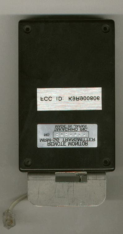
Click to zoom
Application Details
- Equipment Class
- TNB - Licensed Non-Broadcast Station Transmitter
- Date of Grant
- Mar 06, 1999
- Application Purpose
- Original Equipment
- Date of Application
- Dec 20, 1998
- Equipment Note
- UHF Transmitter
- Frequency Range
- 469.50000000 - 469.55000000
- Company
- Chori America Inc
- Country
- United States
Documents & Files
Document Text
Text extracted from the exhibit documents filed with the FCC. Open a document above to read the original.
Users Manual
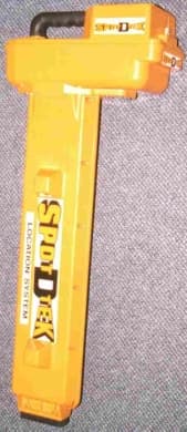
Users Manual FCC ID: K9R900040 Communication with the Mole Map Remote Receiver. The Spot III Tracking Receiver uses a device called the WTX (transmitter), to allow communication between the drill operator and the locator. This device is installed on the underside of the Spot III head section. McLAUGHLIN Manufacturing Company has also designed the SPOT-D-TEK III transmitter to send back any data on the receiver’s LCD screen to a remote monitor at the drill rack. Drill operators find this kind of information invaluable because they can constantly see the face orientation and the pitch of the probe. Plus, the transmitter sends back accurate depth readings in a split second. With the Spot D Tek III Tracking Receiver System, you’ll rarely need to use a walkie-talkie. Installation is very simple. Just plug the black transmitter box into a standard telephone jack located in the head of the receiver. Then, using the ”The device operates on two frequencies: 469.500 and 469.550 MHz. “ The Power Output produced by the WTX is 40mW. The range of the device is +1000 ft. The maximum demonstrated range when used in open terrain at normal operating height is +2000 ft. The temperature The battery life The operating Range The Spot III tracking receiver uses the WTX transmitter to transmit data produced during actual locating. The Spot III device is subject to the following: This device complies with part 15 of the FCC Rules. Operation is subject to the following two conditions: (1) This device may not cause harmful interference, and (2) This device must accept any interference received, including interference that may cause undesired operation.
Users Manual
Users Manual FCC ID: K9R900040 Communication with the Mole Map Remote Receiver. The Spot III Tracking Receiver uses a device called the WTX (transmitter), to allow communication between the drill operator and the locator. This device is installed on the underside of the Spot III head section. McLAUGHLIN Manufacturing Company has also designed the SPOT-D-TEK III transmitter to send back any data on the receiver’s LCD screen to a remote monitor at the drill rack. Drill operators find this kind of information invaluable because they can constantly see the face orientation and the pitch of the probe. Plus, the transmitter sends back accurate depth readings in a split second. With the Spot D Tek III Tracking Receiver System, you’ll rarely need to use a walkie-talkie. Installation is very simple. Just plug the black transmitter box into a standard telephone jack located in the head of the receiver. Then, using the ”The device operates on two frequencies: 469.500 and 469.550 MHz. “ The Power Output produced by the WTX is 40mW. The range of the device is +1000 ft. The maximum demonstrated range when used in open terrain at normal operating height is +2000 ft. The temperature The battery life The operating Range The Spot III tracking receiver uses the WTX transmitter to transmit data produced during actual locating. The Spot III device is subject to the following: This device complies with part 15 of the FCC Rules. Operation is subject to the following two conditions: (1) This device may not cause harmful interference, and (2) This device must accept any interference received, including interference that may cause undesired operation.
Cover Letter(s)
Letter of AuthorizationFCC ID: K9R900040
External Photos
External Photos FCC ID: K9R900040 Page 1 of 2 External Photos FCC ID: K9R900040 Page 2 of 2
ID Label/Location Info
ID Label FCC ID: K9R900040 Page 1 of 1 FCC LABEL FCC Label Information GENERAL DESCRIPTION: This is a topcoated metallized brush stainless polyester film coated with a permanent pressure sensitive acrylic adhesive and backed with a two-side poly coated release liner. UL RECOGNITION: This product is UL recognized for indoor/outdoor use with occasional exposure to lubricating oil and water. FCC ID Label 2” x .75” FCC Label and Location FCC ID: K9R900040 4.8801 1.1186 3.1199 REMOTE MONITOR MRM-S6 TRANSMITTER NO. XXXXXXXXXXX Made In Ja pan FCC ID: K9R900040
Internal Photos
Internal Photos FCC ID: K9R900040 Page 1 of 5 Internal Front Side Internal Photos FCC ID: K9R900040 Page 2 of 5 Internal Back Side Internal Photos FCC ID: K9R900040 Page 3 of 5 Internal Assembled Internal Photos FCC ID: K9R900040 Page 4 of 5 Internal PCB Component side Internal Photos FCC ID: K9R900040 Page 5 of 5 Internal PCB Foil side
Internal Photos
Internal Photos FCC ID: K9R900040 Page 1 of 5 Internal Front Side Internal Photos FCC ID: K9R900040 Page 2 of 5 Internal Back Side Internal Photos FCC ID: K9R900040 Page 3 of 5 Internal Assembled Internal Photos FCC ID: K9R900040 Page 4 of 5 Internal PCB Component side Internal Photos FCC ID: K9R900040 Page 5 of 5 Internal PCB Foil side
Operational Description
Setup Photos FCC ID: K9R900040 Page 1 of 1 Operational Description The EUT is mounted on the pipe locator The EUT is an 40 mW UHF transmitter and is battery powered. The transmitter is a frequency-modulated device operating at one of two fixed frequencies. The transmitter operates at 469.500 and 469.550 MHz. The necessary bandwidth of the transmitted signal is 18 kHz. The emission designator is 18K0F2D. The EUT is an accessory to pipe locating system. The transmitter receives data from a sensor that acts a pipe locator and sends data to a remote monitor. The sensor is a Spot D Tek sensor. The sensor receives a signal at 38 kHz. The remote monitor has a UHF receiver. The transmitter cannot send voice transmissions. The RF amplifier finals are supplied with 4.6 VDC and draw a current of 24 milliamperes under normal operation. The EUT will only be used for data transmission. The EUT uses only frequency modulation. The transmission is a single channel containing quantized information using a modulating subcarrier of 1.28 kHz. The data is encoded into the modulation signal as binary steps from 1.28 to 2.1 kHz with a peak to peak voltage of 1.4 Volts. The deviation is proportional to modulation signal amplitude. It sends only data transmissions. Therefore according to FCC part 2.201, the emissions designator is F2D. There are no provisions for any external or alternate modulating sources.
Parts List/Tune Up Info
Parts List/Tune up Info FCC ID K9R900040 Page 1 of 3 Tune up Information Parts List/Tune up Info FCC ID K9R900040 Page 2 of 3 Tune up Information Parts List/Tune up Info FCC ID K9R900040 Page 3 of 3 Tune up Information
Schematics
Schematics FCC ID K9R900040 Page 1 of 1
Schematics
Schematics FCC ID K9R900040 Page 1 of 1
Test Report
Radiometrics Midwest Corporation Test Document RP-3924 Issue Date: 12-31-98 This report concerns: Original grant Equipment type: UHF Transmitter Transition Rules per 15.37 are not requested. Tests Performed ForTest Facility Chori America, Inc. One Penn Plaza Suite 5440 New York, NY 10119-5498 Radiometrics Midwest Corporation 12 East Devonwood Romeoville, IL 60446 Phone: (815) 293-0772 FAX: (815) 293-0820 [email protected] Test Report Written ByTest Report Approved By Joseph Strzelecki Senior EMC Engineer NARTE EMC-000877-NE Chris W. Carlson Director of Engineering NARTE EMC-000921-NE MEASUREMENT/TECHNICAL REPORT Chori America, Inc. Model WTX FCC ID: K9R900040 APPLICATION FOR CERTIFICATION RF Emission Measurements Performed For Determination of Compliance with the US Code of Federal Regulations Title 47, Chapter I, FCC Part 90.217 As Required for Certification for Intentional Radiators Tests Performed ForFCC IDRadiometrics Test DocumentPage Chori America, Inc. K9R900040RP-39242 of 16 Table of Contents 1.0 General Information ........................................................................................................... 3 1.1 Product Description ........................................................................................................3 1.2 Related Submittals .........................................................................................................3 1.3 Tested System Details.................................................................................................... 3 1.4 Test Methodology ...........................................................................................................3 1.5 Test Facility .................................................................................................................... 3 1.6 Test Equipment ..............................................................................................................3 1.7 Test Specification Requirements.................................................................................... 4 1.7.1 RF Power Output...................................................................................................... 4 1.7.3 Occupied Bandwidth and Spurious Emissions ......................................................... 4 1.8 Test Procedures .............................................................................................................4 1.8.1 RF Power Output...................................................................................................... 4 1.8.2 Occupied Bandwidth ................................................................................................ 5 1.8.4 Frequency Stability ................................................................................................... 5 1.8.5 Field Strength of Spurious Emissions ...................................................................... 5 2.0 System Test Configuration ................................................................................................ 5 2.1 Test System and Justification......................................................................................... 5 2.2 EUT Test Configuration .....................................................................................................6 2.3 Special Accessories ....................................................................................................... 6 2.4 Equipment Modifications ................................................................................................ 6 Figure 2.1 Configuration of Tested System .......................................................................... 7 3.0 Occupied Bandwidth Data ................................................................................................. 8 Figure 3.1 Occupied Bandwidth Plot .................................................................................... 9 Figure 3.2 Occupied Bandwidth Plot .................................................................................. 10 Figure 3.3 Occupied Bandwidth Plot .................................................................................. 11 Figure 3.4 Occupied Bandwidth Plot .................................................................................. 12 Figure 3.5 Occupied Bandwidth Plot .................................................................................. 13 4.0 Radiated Emissions Data (Field Strength of Spurious Radiation) ................................... 14 4.1 Field Strength Calculation ............................................................................................ 15 5.0 RF Power Output Results ................................................................................................ 15 6.0 Frequency Stability .......................................................................................................... 16 Notice: This report must not be reproduced (except in full) without the written approval of Radiometrics Midwest Corporation. Tests Performed ForFCC IDRadiometrics Test DocumentPage Chori America, Inc. K9R900040RP-39243 of 16 1.0 General Information 1.1 Product Description The Model WTX (referred to as the EUT in this report) is a 40 mW UHF Transmitter. The EUT is manufactured by Chori America, Inc. The EUT is battery powered and operates at 469.500 and 469.550 MHz. The EUT is designed to operate with a 20 kHz channel bandwidth. 1.2 Related Submittals Chori America, Inc. is not submitting any other submittals related to the EUT. The associated receiver is operated under FCC rules for unintentional radiators. It is subject to the FCC requirements pursuant to the Certification equipment authorization under Part 15 subpart B and has been previously approved as FCC ID: K9R900808. 1.3 Tested System Details The FCC ID's for all equipment, plus descriptions of all cables used in the tested system which have grants, are: Model Number Serial NumberFCC ID Manufacturer & Description …
Text truncated - open the document above for the full version.
Test Report
Radiometrics Midwest Corporation Test Document RP-3924 Issue Date: 12-31-98 This report concerns: Original grant Equipment type: UHF Transmitter Transition Rules per 15.37 are not requested. Tests Performed ForTest Facility Chori America, Inc. One Penn Plaza Suite 5440 New York, NY 10119-5498 Radiometrics Midwest Corporation 12 East Devonwood Romeoville, IL 60446 Phone: (815) 293-0772 FAX: (815) 293-0820 [email protected] Test Report Written ByTest Report Approved By Joseph Strzelecki Senior EMC Engineer NARTE EMC-000877-NE Chris W. Carlson Director of Engineering NARTE EMC-000921-NE MEASUREMENT/TECHNICAL REPORT Chori America, Inc. Model WTX FCC ID: K9R900040 APPLICATION FOR CERTIFICATION RF Emission Measurements Performed For Determination of Compliance with the US Code of Federal Regulations Title 47, Chapter I, FCC Part 90.217 As Required for Certification for Intentional Radiators Tests Performed ForFCC IDRadiometrics Test DocumentPage Chori America, Inc. K9R900040RP-39242 of 16 Table of Contents 1.0 General Information ........................................................................................................... 3 1.1 Product Description ........................................................................................................3 1.2 Related Submittals .........................................................................................................3 1.3 Tested System Details.................................................................................................... 3 1.4 Test Methodology ...........................................................................................................3 1.5 Test Facility .................................................................................................................... 3 1.6 Test Equipment ..............................................................................................................3 1.7 Test Specification Requirements.................................................................................... 4 1.7.1 RF Power Output...................................................................................................... 4 1.7.3 Occupied Bandwidth and Spurious Emissions ......................................................... 4 1.8 Test Procedures .............................................................................................................4 1.8.1 RF Power Output...................................................................................................... 4 1.8.2 Occupied Bandwidth ................................................................................................ 5 1.8.4 Frequency Stability ................................................................................................... 5 1.8.5 Field Strength of Spurious Emissions ...................................................................... 5 2.0 System Test Configuration ................................................................................................ 5 2.1 Test System and Justification......................................................................................... 5 2.2 EUT Test Configuration .....................................................................................................6 2.3 Special Accessories ....................................................................................................... 6 2.4 Equipment Modifications ................................................................................................ 6 Figure 2.1 Configuration of Tested System .......................................................................... 7 3.0 Occupied Bandwidth Data ................................................................................................. 8 Figure 3.1 Occupied Bandwidth Plot .................................................................................... 9 Figure 3.2 Occupied Bandwidth Plot .................................................................................. 10 Figure 3.3 Occupied Bandwidth Plot .................................................................................. 11 Figure 3.4 Occupied Bandwidth Plot .................................................................................. 12 Figure 3.5 Occupied Bandwidth Plot .................................................................................. 13 4.0 Radiated Emissions Data (Field Strength of Spurious Radiation) ................................... 14 4.1 Field Strength Calculation ............................................................................................ 15 5.0 RF Power Output Results ................................................................................................ 15 6.0 Frequency Stability .......................................................................................................... 16 Notice: This report must not be reproduced (except in full) without the written approval of Radiometrics Midwest Corporation. Tests Performed ForFCC IDRadiometrics Test DocumentPage Chori America, Inc. K9R900040RP-39243 of 16 1.0 General Information 1.1 Product Description The Model WTX (referred to as the EUT in this report) is a 40 mW UHF Transmitter. The EUT is manufactured by Chori America, Inc. The EUT is battery powered and operates at 469.500 and 469.550 MHz. The EUT is designed to operate with a 20 kHz channel bandwidth. 1.2 Related Submittals Chori America, Inc. is not submitting any other submittals related to the EUT. The associated receiver is operated under FCC rules for unintentional radiators. It is subject to the FCC requirements pursuant to the Certification equipment authorization under Part 15 subpart B and has been previously approved as FCC ID: K9R900808. 1.3 Tested System Details The FCC ID's for all equipment, plus descriptions of all cables used in the tested system which have grants, are: Model Number Serial NumberFCC ID Manufacturer & Description …
Text truncated - open the document above for the full version.
Test Setup Photos
Setup Photos FCC ID: K9R900040 Page 1 of 1 Radiated Emissions Setup The EUT is mounted on the pipe locator
Contact Information
Applicant
Toru Nakamura(President)
Technical Contact
Radiometrics Midwest CorporationJoseph R Strzelecki
[email protected]815-293-0772
12 East Devonwood Av. · Romeoville, Illinois · United States
Non-Technical Contact
Radiometrics Midwest CorporationJoan E Strzelecki
[email protected]815-293-0772
Test Firm
Radiometrics Midwest CorporationJoseph Strzelecki
815-293-0772Fax: 815-293-0820
Technical Specifications
| # | Rule Parts | Frequency Range | Power Output | Emission | Tolerance |
|---|---|---|---|---|---|
| 1 | 90 | 469.5 MHz - 469.55 MHz | 40.00 mW | 18K0F2D | 0.0005000000 % |
Other Applications from Chori America Inc
K9R900041
Jan 27, 2000Bore location system
Equipment Class
TNB - Licensed Non-Broadcast Station Transmitter
K9R900042
Nov 22, 1999Pipe location system
Equipment Class
CXX - Communications Rcvr for use w/ licensed Tx and CBsK9R900806
Feb 06, 1994TNB - Licensed Non-Broadcast Station Transmitter
Equipment Class
TNB - Licensed Non-Broadcast Station TransmitterK9R900808
Feb 06, 1994CXX - Communications Rcvr for use w/ licensed Tx and CBs
Equipment Class
CXX - Communications Rcvr for use w/ licensed Tx and CBs