K9R900041Bore location system
Chori America Inc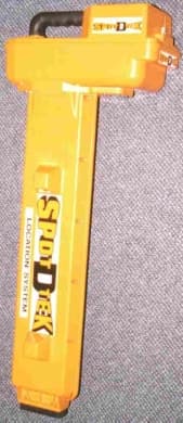
Click to zoom
Application Details
- Equipment Class
- TNB - Licensed Non-Broadcast Station Transmitter
- Date of Grant
- Jan 27, 2000
- Application Purpose
- Original Equipment
- Date of Application
- Oct 18, 1999
- Equipment Note
- Bore location system
- Frequency Range
- 464.50000000 - 469.55000000
- Company
- Chori America Inc
- Country
- United States
Documents & Files
Document Text
Text extracted from the exhibit documents filed with the FCC. Open a document above to read the original.
Users Manual
SPOT D TEK IV MANUAL FCC INFORMATION - SPOT D TEK The UHF transmitter within the SPOT D TEK has been type accepted in Part 90 (Private Land Mobile Services) at 464.500,464.550,469.500 & 469.550 MHz with a power output of 40 milliwatts and emissions designator 20KOF2D. FCC rules require licensing by the purchaser. Requests for applications forms or information may be obtained from the Federal Communications Commission, Gettysburg, PA 17325. The SPOT D TEK 38 kHz Probe transmitter has been verified under FCC rules, part 15, and requires no licensing. Note: The Digital equipment in the SPOT D TEK equipment has been tested and found to comply with the limits for a Class B digital device, pursuant to part 15 of the FCC Rules. These limits are designed to provide reasonable protection against harmful interference in a residential installation. This equipment generates, uses and can radiate radio frequency energy and, if not installed and used in accordance with the instructions, may cause harmful interference to radio communications. However, there is no guarantee that interference will not occur in a particular installation. If this equipment does cause harmful interference to radio or television reception, which can be determined by turning the equipment off and on, the user is encouraged to try to correct the interference by one or more of the following measures: —Reorient or relocate the receiving antenna. —Increase the separation between the equipment and receiver. —Consult the dealer or an experienced radio/TV technician for help. Changes or modifications not expressly approved by Chori America or an authorized representative could void the user's authority to operate the equipment. The Spot D TEK IV is authorized for use only with the standard antenna. SPOT D TEK IV OPERATION OF RADIO FREQUENCY CHANNELS To operate the the frequency selection function of the Spot D Tek unit, press the Frequency button on the operation panel. The current operating frequency is displayed on the LCD. To go to the next channel or frequency press the same Frequency button until desired channel is displayed after 3 seconds, the channel is updated to current use.
Cover Letter(s)
FCC ID: K9R900041
External Photos
FCC ID: K9R900041 Side view of EUTFront view of EUT
ID Label/Location Info
FCC ID: K9R900041 FCC ID LABEL PLACED HERE Side View Front View
Internal Photos
FCC ID: K9R900041 Interface board with Transmitter enclosed in metal box Interface board: foil side Interface board with Transmitter Cover removed showing component side of Transmitter Transmitter Board: Foil side Transmitter installed inside of Pipe Locator The Interface and Transmitter boards were completely scanned but the rest of the boards were not scanned as they do not contain RF circuitry
Operational Description
Page 1 of 1 FCC ID: K9R900042 Product Description 1.1 Product Description The EUT is an UHF transmitter for a pipe locating system. The Model Spot-D-Tek IV is a 100 mW UHF Transmitter. Chori America, Inc manufactures the transmitter. It is battery powered and operates at 464.500, 464.550, 469.500 and 469.550 MHz. It is designed to operate with a 20 kHz channel bandwidth. . The emission designator is 20K0F2D. The transmitter receives data from a sensor that acts a pipe locator and sends data to a remote monitor. The sensor receives a signal at 38 kHz. The remote monitor has an UHF receiver. The transmitter cannot send voice transmissions. The EUT will only be used for data transmission. The pipe locator operates at 38 kHz is under FCC rules for intentional radiators. It is subject to the FCC requirements pursuant to the Verification equipment authorization under Part 15.213.
Test Report
Radiometrics Midwest Corporation Test Document RP-4082 Issue Date: 10/19/99 This report concerns: Original grant Equipment type: UHF Transmitter Tests Performed ForTest Facility Chori America, Inc. One Penn Plaza Suite 5440 New York, NY 10119-5498 Radiometrics Midwest Corporation 12 East Devonwood Romeoville, IL 60446 Phone: (815) 293-0772 FAX: (815) 293-0820 [email protected] Test Report Written ByTest Report Approved By Joseph Strzelecki Senior EMC Engineer NARTE EMC-000877-NE Chris W. Carlson Director of Engineering NARTE EMC-000921-NE MEASUREMENT/TECHNICAL REPORT Chori America, Inc. Model Spot D Tek IV FCC ID: K9R900041 APPLICATION FOR CERTIFICATION RF Emission Measurements Performed For Determination of Compliance with the US Code of Federal Regulations Title 47, Chapter I, FCC Part 90.217 As Required for Certification for Intentional Radiators Tests Performed ForFCC IDRadiometrics Test DocumentPage Chori America, Inc. K9R900041RP-40822 of 10 Table of Contents 1.0 General Information ........................................................................................................... 3 1.1 Product Description ........................................................................................................3 1.2 Related Submittals .........................................................................................................3 1.3 Tested System Details.................................................................................................... 3 1.4 Test Methodology ...........................................................................................................3 1.5 Test Facility .................................................................................................................... 3 2.0 Test Specification Requirements ....................................................................................... 3 2.1 RF Power Output............................................................................................................4 2.2 Occupied Bandwidth....................................................................................................... 4 3.0 Test Procedures ................................................................................................................ 4 3.1 RF Power Output............................................................................................................4 3.2 Occupied Bandwidth....................................................................................................... 4 3.3 Frequency Stability .........................................................................................................4 4.0 System Test Configuration ................................................................................................ 5 4.1 Test System and Justification......................................................................................... 5 4.2 EUT Test Configuration .................................................................................................. 5 4.3 Special Accessories ....................................................................................................... 5 4.4 Equipment Modifications ................................................................................................ 5 5.0 Occupied Bandwidth Results ............................................................................................. 6 Figure 5.1 Occupied Bandwidth Plot .................................................................................... 7 Figure 5.2 Occupied Bandwidth Plot .................................................................................... 8 6.0 RF Power Output Results .................................................................................................. 9 7.0 Frequency Stability Results ............................................................................................. 10 Notice: This report must not be reproduced (except in full) without the written approval of Radiometrics Midwest Corporation. Tests Performed ForFCC IDRadiometrics Test DocumentPage Chori America, Inc. K9R900041RP-40823 of 10 1.0 General Information Since the EUT is less than 120 mW it is required to meet the technical requirements of 90.217. 1.1 Product Description The Model Spot-D-Tek IV (referred to as the EUT in this report) is a 100 mW UHF Transmitter. The EUT is manufactured by Chori America, Inc. The EUT is battery powered and operates at 464.500, 464.550, 469.500 and 469.550 MHz. The EUT is designed to operate with a 20 kHz channel bandwidth. . The emission designator is 20K0F2D. The transmitter receives data from a sensor that acts a pipe locator and sends data to a remote monitor. The sensor receives a signal at 38 kHz. The remote monitor has an UHF receiver. The transmitter cannot send voice transmissions. The EUT will only be used for data transmission. 1.2 Related Submittals The associated receiver is operated under FCC rules for unintentional radiators. It is subject to the FCC requirements pursuant to the Certification equipment authorization under Part 15 subpart B and is being currently submitted as FCC ID: K9R900042. 1.3 Tested System Details The FCC ID's for all equipment, plus descriptions of all cables used in the tested system which have grants, are: Model Number Serial NumberFCC ID Manufacturer & Description Cable Descriptions M/N: Spot D Tek IVK9R900041Chori America, Inc. Location System None; Battery Operated 1.4 Test Methodology The test procedures used are in accordance with the FCC part 90 rules. The specific procedures are described herein. Radiated testing was performed at an antenna to EUT distance of 3 meters. The antenna was raised and lowered from 1 to 4 meters. Since the EUT is battery powered, no AC conducted emissions were performed. 1.5 Test Facility The test site used to collect the radiated data is located on 12 E Devonwood in Romeoville, Illinois. Details of the site character…
Text truncated - open the document above for the full version.
Test Setup Photos
FCC ID: K9R900041 Photographs of Test Setup-Transmitter
Contact Information
Applicant
Toru Nakamura(President)
Technical Contact
Radiometrics Midwest CorporationJoseph R Strzelecki
[email protected]815-293-0772
12 East Devonwood Av. · Romeoville, Illinois · United States
Non-Technical Contact
Radiometrics Midwest CorporationJoan E Strzelecki
[email protected]815-293-0772
Test Firm
Radiometrics Midwest CorporationJoseph Strzelecki
815-293-0772Fax: 815-293-0820
Technical Specifications
| # | Rule Parts | Frequency Range | Power Output | Emission | Tolerance |
|---|---|---|---|---|---|
| 1 | 90.217(b) | 464.5 MHz - 469.55 MHz | 100.00 mW | 20K0F2D | 5.0000000000 ppm |
Other Applications from Chori America Inc
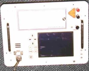
K9R900042
Nov 22, 1999Pipe location system
Equipment Class
CXX - Communications Rcvr for use w/ licensed Tx and CBs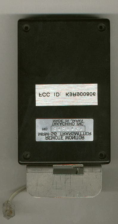
K9R900040
Mar 06, 1999UHF Transmitter
Equipment Class
TNB - Licensed Non-Broadcast Station TransmitterK9R900806
Feb 06, 1994TNB - Licensed Non-Broadcast Station Transmitter
Equipment Class
TNB - Licensed Non-Broadcast Station TransmitterK9R900808
Feb 06, 1994CXX - Communications Rcvr for use w/ licensed Tx and CBs
Equipment Class
CXX - Communications Rcvr for use w/ licensed Tx and CBs