KBCIX100XUSI-WLBTBluetooth Module
General Dynamics Itronix Corporation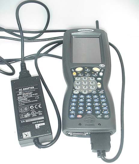
Click to zoom
Application Details
- Equipment Class
- DSS - Part 15 Spread Spectrum Transmitter
- Date of Grant
- Oct 03, 2006
- Application Purpose
- Original Equipment
- Date of Application
- Oct 03, 2006
- Equipment Note
- Bluetooth Module
- Frequency Range
- 2402.00000000 - 2480.00000000
- Country
- United States
Documents & Files
Document Text
Text extracted from the exhibit documents filed with the FCC. Open a document above to read the original.
Users Manual
Handheld Computer Help English Fran çais Deutsch Spanish Handheld Computer Help Controls Batteries Maintaining Your Computer Using Your Computer Safely CompactFlash Cards Peripherals ActiveSync Troubleshooting Index Legal Information Controls The handheld computer is equipped with a 52-key alphanumeric keypad including cursor keys and a few special function keys. Other functions are available via the touch screen. Backlight Function Keys Stylus Entering Data Resetting Your Computer Backlight Press the Blue Function key along with the large Yellow backlight key in the upper-right corner of the keypad to turn the backlight on or off. To adjust brightness press and hold the Orange Function key near the upper-left corner of the keypad; then push the lowercase o key to increase brightness or press the 7 key to decrease brightness. The backlight is on by default and turns off automatically after 1 minute of inactivity when on battery power. These settings may be adjusted in the computer's display settings. When the display backlight turns on, the keypad backlight also turns on. It turns off whenever the display backlight turns off. See Also Stylus Function Keys Entering Data Resettin g Your Computer Page 1 of 17Handheld Computer Help 05/05/2004file://C:\Documents%20and%20Settings\jonathan\Local%20Settings\Temp\Handheld%2... Function Keys The FN keys have many functions. The most commonly used functions are: z Orange FN + Power: When held for five seconds this performs a Soft Reset. z Orange FN + Blue FN + Power: When held for five seconds this performs a Hard Reset. CAUTION The Hard Reset is an emergency procedure only. Use the Soft Reset instead if possible. If you Hard Reset, you will lose the settings saved in the operating system as well as all data stored in RAM. You will have to recalibrate your touch screen and personal data when you restart. z Blue FN + Yellow Backlight: Toggles the backlight The FN keys may also have different functions depending on the program in use. Below is a list of key combination functions associated with the Orange and Blue function keys: Key Orange FN Blue FN A| B~BREAK D: E# F; G"< H`> I*INS J'/ K. L? N` O( P) PAUSE Q! R$PRINT SCREEN S\SCROLL LOCK T%= U& Venter Volume Control W@{ X} Y^[ Z] 1F1F11 Page 2 of 17Handheld Computer Help 05/05/2004file://C:\Documents%20and%20Settings\jonathan\Local%20Settings\Temp\Handheld%2... See your Getting Started Guide for a complete list of key functions See Also Stylus Entering Data Resetting Your Computer Using the Stylus The stylus is designed to be light-weight and comfortable to use, as well as being gentle on the touch screen. It is stored in a channel in the back of the terminal. To remove the stylus from the channel, press on its textured part and push it up and out. NOTE It is good practice to return the stylus to the holder when not in use. If you lose the stylus, you may use your fingertips instead, but they are not as precise. CAUTION Do not use a ballpoint pen or sharp pointed object to operate the touch screen, as this can damage the screen. See Also Backlight Function Keys Entering Data Resetting Your Computer 2F2F12 3F3F13 4F4F14 5F5F15 6F6F16 7F7F17 8F8F18 9F9F19 0F10F20 TabBKTAB SpcBkSp- right Yellow Right ScanBacklight left YellowLeft Scan Up ArrowPgUp Down ArrowPgDn Right ArrowEndStart Left ArrowHome AltenterEsc Page 3 of 17Handheld Computer Help 05/05/2004file://C:\Documents%20and%20Settings\jonathan\Local%20Settings\Temp\Handheld%2... Entering Data Use the keypad or input panel to enter alpha and numerical data. Use the cursor keys or your stylus to move the cursor around the screen. Use Function Keys for special characters and functions. When a field appears requiring text entry, the input panel (soft keyboard) will pop up. This can then be operated with the stylus. To change input panel settings, see Input Panel. See Also Function Keys Backlight Stylus Resetting Your Computer Resetting your Handheld Computer If your handheld computer locks up or fails to operate, you may need to reset it in one of two ways. z Soft Reset: Hold down both the Power and Orange FN keys for about five seconds. The screen will dim and the handheld computer will perform a Soft Reset. The Soft Reset does not affect the operating system and no data loss occurs. z Hard Reset: Hold down the Power , Orange FN , and Blue FN keys simultaneously for about ten seconds. This will perform a Hard Reset, resulting in data loss. CAUTION The Hard Reset is an emergency procedure only. Use the Soft Reset instead if possible. If you Hard Reset, you will lose the settings saved in the operating system as well as all data stored in RAM. You will have to recalibrate your touch screen and reenter your personal data when you restart. See Also Backlight Stylus Function Keys Entering Data Batteries Battery Information Checking the Batteries Battery Conservation Battery Charging Battery Replacement Battery Safety Battery Storage Page 4 of 17Handheld Computer Help 05/05/2004file://C:\Documents%20and%20Settings\jonathan\Local%20Settings\Temp\Handheld%2... Battery Information The computer's primary battery is a rechargeable Lithium-Ion (Li-Ion) pack. DO NOT use other batteries. They may damage your handheld computer. After inserting a new Li-Ion battery pack, charge it to 100% before use. This ensures that the battery pack's power gauge calculations will be correct. Frequent incomplete charges lead to progressively larger errors that only a full charge can fix. Charge on AC power at least 7 hours to ensure the internal backup battery is also fully charged; however it may take longer if the ambient temperature is extremely hot or cold. The internal backup battery retains data up to 48 hours if the main battery pack is fully discharged or removed. Its charge is automatically topped-off whenever the handheld computer is awake and on external or main battery power. To ensure data integrity, the main battery should always be kept charged and important data sh…
Text truncated - open the document above for the full version.
Users Manual
All rights are reserved by USI. No part of this technical document can be reproduced in any form without permission of USI . 1 Data Sheet of 802.11g WM-BG-MR -01 B2B Wireless Lan +BT Combo Module Data Sheet Apr 14th. 2006 Rev 2.5 802.11g Wireless LAN SiP Module (WM-BG-MR -01) www.usi.com.tw 802.11g Wireless LAN+BT SiP combo Module V2.2 All rights are reserved by USI. No part of this technical document can be reproduced in any form without permission of USI . 2 Introduction The 802.11 Wireless SiP module WM-BG-MR-01 which refers as “SiP-g combo module” is a small size module that provides full function of 802.11g/b and Bluetooth class 2 on a tiny module via 60 pins board to board connector. This multi- functionality and board to board physical interface provides 16 bit PC Card /CF+ bus interface for WiFi and UART for Bluetooth. The small size & low profile physical design make it easier for system design to enable high performance wireless connectivity without space constrain. The low power consumption (Sleep mode 1.2 mA) and excellent radio performance make it the best solution for OEM customers who require embedded 802.11g Wi-Fi + Bluetooth features, such as, Wireless PDA, Scanner Smart phone, Media player slim type Notebook, barcode ,mini-Printer, VoIP phone etc. For 802.11g feature, Marvell “Libertas” chipset solution is adopted and CSR BlueCore 03-ROM for Bluetooth. The Radio architecture & high integration MAC/BB chip provide excellent sensitivity with rich system performance. Two antenna connectors provide antenna connectivity for each function. WM-BG-MR-01 provides outstanding BT WiFi co- existence solution through internal 2 wires , hardware interface to optimized connection with CSR Bluetooth solution even without good antenna isolation between BT & WiFi module. In addition to WEP 64/128, WPA and TKIP, AES is supported to provide the latest security requirement on your network. For the software and driver development, USI provides extensive technical document and reference software code for the system integration under the agreement of Marvell International Ltd. Features z Lead Free design which supporting Green design requirement, RoHS Compliance. z 2 wires, hardware signaling BT WiFi co- existence supported. z Small size suitable for low volume system integration.PCM audio interface supported. z Low power consumption & excellent power management performance, extend battery life. z 2.412-2.484 GHz two SKUs for worldwide market. z Easy for integration into mobile and handheld device with flexible system configuration and antenna design. 802.11g Wireless LAN+BT SiP combo Module V2.2 All rights are reserved by USI. No part of this technical document can be reproduced in any form without permission of USI . 3 Change Sheet Rev. Date Description of change Approval & Date Page Par Change(s) 1.0 10/1/04 All All Draft version for Review 2.0 04/11/05 6,15, 17,22 ,23, 25~2 7 1. Executive summary for target available date from “the middle of 1Q 2005” to “ the end of 2Q” 2. Output power for 11g is 13 +/- 1dBm 3. Update the mech. Drawing . 4. Modify the function description for Marvell Transceiver from ”8010” to “8015” 5. Correct the Pin Definition for xxx_B is for “active_high” 6. add description for Pin 28;36;43;58 ; which reserved for BT’s PCM interface , make it no confuse in customer reading. 2.1 04/18/05 25 1. correct the pin definition for Pin24 from “Control signal to enable engineer testing mode “ to “ Output signal to indicate 16 bit IO operation. This signal is connected to ground at module side to indicate 16 bit IO..” then Type is for GND to indicate the module under the mode for 16bit IO. 2.2 04/28/05 24 1. Pin A10 pin definition change from “ the pin is open to “This address range is mainly used for accessing the CIS in Memory Mode. Signal HA0 is not used in word access mode.” , Type change from “ No connection” to “Input , PD,5VT” 2.3 10/31/05 2, 8, 9 Power Consumption 2.4 11/08/05 25,26 , 27 Add SDIO Pin Definition 2.5 04/14/06 17, all 1. Specify connectors for BT and WiFi 2. Add page numbers 802.11g Wireless LAN+BT SiP combo Module V2.2 All rights are reserved by USI. No part of this technical document can be reproduced in any form without permission of USI . 4 TABLE OF CONTENTS 1. EXECUTIVE SUMMARY................................................................................................................ 6 2. DELIVERABLES............................................................................................................................. 6 3. REFERENCE DOCUMENTS......................................................................................................... 7 4. TECHNICAL SPECIFICATION..................................................................................................... 8 4.1. ABSOLUTE MAXIMUM RATING ............................................................................................... 8 4.2. RECOMMENDABLE OPERATION CONDITION ...................................................................... 8 4.2.1. TEMPERATURE, HUMIDITY ............................................................................................. 8 4.2.1. VOLTAGE AND CURRENT ............................................................................................... 8 BLUETOOTH ...................................................................................................................................... 8 4.3. COMPACTFLASH SPECIFICATION ......................................................................................... 9 4.3.1. DC ELECTRICALS ............................................................................................................. 9 4.3.2. AC ELECTRICALS ............................................................................................................. 9 4.3.3. COMPACTFLASH PROTOCAL TIMING ......................................................................... 10 4.4. WIRELESS SPECIFICATIONS.....................…
Text truncated - open the document above for the full version.
Cover Letter(s)
Celltech Labs Inc. 1955 Moss Court, Kelowna, B.C. Canada V1Y 9L3 Tel. 250-448-7047 • Fax. 250-448-7046 • e-mail: [email protected] www.celltechlabs.com September 27, 2006 Timco Engineering, Inc. Telecommunication Certification Body 849 NW State Road 45 Newberry, FL 32669 SUBJECT: ITRONIX CORPORATION FCC ID: KBCIX100XUSI-WLBT Part 15(C) - Certification (Composite) Limited Modular Approval Application On behalf of Itronix Corporation is a Limited Modular Approval application for Part 15 Subpart C Certification of the W M-BG-MR-01 802.11b/g W LAN/Bluetooth Combo Module (manufactured by Universal Scientific Industrial Co., Ltd.) installed in the Itronix Corporation IX100X Series Rugged Handheld PC utilizing an internal dipole antenna (WLAN) and internal printed circuit antenna (Bluetooth). The W M-BG-MR-01 802.11b/g W LAN/Bluetooth Combo Module with internal antennas is installed in the IX100X by Itronix Corporation prior to shipment and is not intended for installation or reconfiguration by the end user. A Part 15C certification application (DSS) for the Bluetooth portion of the combo module is submitted simultaneously with this application under the same FCC ID: KBCIX100XUSI-W LBT. The 802.11b/g W LAN and Bluetooth can transmit simultaneously. Co-transmit radiated spurious emissions measurements were evaluated during the EMC measurements described in this filing and were found to be in compliance. A co-transmit SAR evaluation was also performed and the measurement data is reported in the SAR Test Report exhibit in this filing. The 802.11bg/Bluetooth Combo Module can also be co-located in the IX100X Handheld PC with an optional AirCard 860 Dual-Band GSM/GPRS/EDGE/UMTS PCMCIA Modem (manufactured by Sierra Wireless Inc.). A separate Limited Modular Approval Certification application for the AirCard 860 is submitted simultaneously with this application (FCC ID: KBCIX100XAC860). The Bluetooth portion of the W M-BG-MR-01 combo module can transmit simultaneously with the AirCard 860 modem. Co-transmit radiated spurious emissions measurements were evaluated during the EMC measurements of the Bluetooth and were found to be in compliance. The 802.11bg W LAN and AirCard 860 do not co-transmit (please refer to the applicant’s attestation letter). The AirCard 860 is also installed in the IX100X by Itronix Corporation prior to shipment and is not intended for installation or reconfiguration by the end user. The IX100X Handheld PC can be configured by Itronix Corporation to contain either one of the internal radios described above or both. It is the intention and purpose of the two referenced Limited Modular Approval applications that all three IX100X host PC configuration options will be approved for certification within these submittals. Depending on the transmitter configuration(s) installed, Itronix Corporation will label the IX100X host PC accordingly with the appropriate FCC ID label(s) applicable for the specific configuration(s). Model(s): IX100XUSI-WLBT Transmitter Type: 802.11b/g WLAN/Bluetooth Combo Module Host PC Type: Itronix IX100X Series Rugged Handheld PC Device Classification(s): Digital Transmission System (DTS) - 802.11b/g WLAN Part 15 Spread Spectrum Transmitter (DSS) - Bluetooth Mode(s) of Operation: Direct Sequence Spread Spectrum (802.11b/g WLAN) Frequency Hopping Spread Spectrum (Bluetooth) Transmit Frequency Range(s): 2412 - 2462 MHz (802.11b/g WLAN) 2402 – 2480 MHz (Bluetooth) Max. RF Output Power Tested: 0.039 Watts (15.93 dBm) Peak Conducted (802.11b) 0.031 Watts (14.98 dBm) Peak Conducted (802.11g) 0.0024 Watts (3.72 dBm) Peak Conducted (Bluetooth) Antenna Type(s) Tested: WLAN: Internal Dipole (Top Center above LCD Display) Bluetooth: Internal Printed Circuit (Right Side of LCD Display) Submitted within this application is the TCB Form 731, applicant’s authorization letter, applicant’s long-term confidentiality request letter, applicant’s attestation letter, applicant’s Limited Modular Approval letter, Part 15(C) EMC measurement report data and test setup photographs, SAR RF exposure measurement report data and test setup photographs, FCC ID label and location, internal and external device photographs, antenna specifications, block diagram (confidential), schematic diagrams (confidential), operational description (confidential), WM-BG-MR-01 integrator manual, and the IX100X user manual (preliminary) with RF exposure information. If you have any questions or comments concerning the above, please contact the undersigned. Sincerely, Jonathan Hughes General Manager Celltech Labs Inc. cc: Itronix Corporation
Cover Letter(s)
12825 E. Mirabeau Parkway SPOKANE VALLEY, W A 99216 509.624.6600 800.441.1309 FAX 509.626.4203 www.itronix.com September 20, 2006 Federal Communications Commission Equipment Authorization Branch 7435 Oakland Mills Road Columbia, MD 21046 Re: Itronix Corporation FCC ID: KBCIX100XUSI-WLBT FCC Part 15(C) - Certification Limited Modular Approval Itronix Corporation is requesting limited modular approval for the WM-BR-MR-01 802.11bg/Bluetooth combo module installed in the IX100X Rugged Handheld PC. The internal radio meets the requirements for limited modular approval as detailed in FCC Public Notice DA00-1407. Compliance to each of the requirements is described below: 1. "The modular transmitter must have its own RF shielding." The module contains in its own RF shielding. Please see the Internal Photos exhibit. 2. "The modular transmitter must have buffered modulation/data inputs. (if such inputs are provided)" The module contains buffered data inputs to ensure compliance with Part 15 requirements under conditions of excessive data rates or over-modulation. 3. "The modular transmitter must have its own power supply regulation." The module contains its own power supply regulation to ensure compliance with Part 15 requirements regardless of the quality or level of external DC supplying the module from the host unit. 4. "The modular transmitter must comply with the antenna requirements of Section 15.203 and 15.204(c)." The module complies with the antenna requirements described in the sections. 5. "The modular transmitter must be tested in a stand-alone configuration." The module was not tested in a stand-alone configuration. This would apply to modular approval and this application is for a limited modular approval. 6. "The modular transmitter must be labeled with its own FCC ID." The module is not labeled with its own FCC ID. The IX100X will contain the FCC ID label. Please see FCC ID label and location exhibit. 7. "The modular transmitter must comply with any specific rule or operating requirements applicable to the transmitter and the manufacturer must provide adequate instructions along with the module to explain any such requirements." The module is compliant with all applicable FCC rules as indicated in the filing. 8. The modular transmitter must comply with any applicable RF exposure requirements." The module is compliant with all applicable FCC RF exposure requirements as indicated in the filing. Sincerely,
Cover Letter(s)
12825 E. Mirabeau Parkway SPOKANE VALLEY, WA 99216 509.624.6600 800.441.1309 FAX 509.626.4203 www.itronix.com September 28, 2006 Federal Communications Commission Equipment Authorization Branch 7435 Oakland Mills Road Columbia, MD 21046 Re: Itronix Corporation FCC ID: KBCIX100XUSI-WLBT FCC Part 15.247 Certification Request for Confidentiality Pursuant to 47 CFR 0.457(d) and 47 CFR 0.459 of the FCC Rules, Itronix Corporation hereby request long- term confidentiality as outlined below: Exhibit Type File Name Block Diagram WM-BG-MR-01 Block Diagram.pdf Schematics WM-BG-MR-01 Schematic Diagrams.pdf Operational Description WM-BG-MR-01 Operational Description.pdf Operational Description WM-BG-MR-01 WLAN Antenna Specification.pdf Operational Description WM-BG-MR-01 Bluetooth Antenna Specification.pdf These documents contain detailed system and equipment description and related information about the product in which Itronix Corporation and Universal Scientific Industrial Electronics Industries Ltd. considers to be proprietary, confidential, and a custom design and, otherwise, would not release to the general public. Since this design is a basis from which future technological products will evolve, Itronix Corporation and Universal Scientific Industrial Electronics Industries Ltd. considers that this information would be of benefit to its competitors, and that the disclosure of the information in these documents would give competitors an unfair advantage in the market. Sincerely,
External Photos
2006 Celltech Labs Inc. ITRONIX CORPORATION FCC ID(s): KBCIX100XUSI-WLBT, KBCIX100XAC860 802.11bg/Bluetooth installed in IX100X Handheld PC (with optional AC860 Modem) Celltech Project No.: 750 EXTERNAL DUT PHOTOGRAPHS Front of IX100X Handheld PC 2006 Celltech Labs Inc. ITRONIX CORPORATION FCC ID(s): KBCIX100XUSI-WLBT, KBCIX100XAC860 802.11bg/Bluetooth installed in IX100X Handheld PC (with optional AC860 Modem) Celltech Project No.: 750 EXTERNAL DUT PHOTOGRAPHS Back of IX100X Handheld PC 2006 Celltech Labs Inc. ITRONIX CORPORATION FCC ID(s): KBCIX100XUSI-WLBT, KBCIX100XAC860 802.11bg/Bluetooth installed in IX100X Handheld PC (with optional AC860 Modem) Celltech Project No.: 750 Bottom end of IX100X Handheld PC Left Side of IX100X Handheld PC Right Side IX100X Handheld PC EXTERNAL DUT PHOTOGRAPHS Top end of IX100X Handheld PC 2006 Celltech Labs Inc. ITRONIX CORPORATION FCC ID(s): KBCIX100XUSI-WLBT, KBCIX100XAC860 802.11bg/Bluetooth installed in IX100X Handheld PC (with optional AC860 Modem) Celltech Project No.: 750 EXTERNAL DUT PHOTOGRAPHS IX100X Battery Compartment Lithium-ion Battery Lithium-ion Battery Nearson ¼-wave Helix Antenna (P/N: 47-0180-003) (for optional AC860 Modem transmit operation only) 2006 Celltech Labs Inc. ITRONIX CORPORATION FCC ID(s): KBCIX100XUSI-WLBT, KBCIX100XAC860 802.11bg/Bluetooth installed in IX100X Handheld PC (with optional AC860 Modem) Celltech Project No.: 750 EXTERNAL DUT PHOTOGRAPHS 2006 Celltech Labs Inc. ITRONIX CORPORATION FCC ID(s): KBCIX100XUSI-WLBT, KBCIX100XAC860 802.11bg/Bluetooth installed in IX100X Handheld PC (with optional AC860 Modem) Celltech Project No.: 750 EXTERNAL DUT PHOTOGRAPHS IX100X Handheld PC with Carry Case and Shoulder-Strap accessory (P/N: 77041A) (with JABRA Ear-Microphone accessory) 2006 Celltech Labs Inc. ITRONIX CORPORATION FCC ID(s): KBCIX100XUSI-WLBT, KBCIX100XAC860 802.11bg/Bluetooth installed in IX100X Handheld PC (with optional AC860 Modem) Celltech Project No.: 750 IX100X with Carry Case accessory (P/N: 77041A) IX100X with Carry Case accessory (P/N: 77041A) EXTERNAL DUT PHOTOGRAPHS Front of Carry Case accessory (P/N: 77041A) Back of Carry Case accessory (P/N: 77041A) 2006 Celltech Labs Inc. ITRONIX CORPORATION FCC ID(s): KBCIX100XUSI-WLBT, KBCIX100XAC860 802.11bg/Bluetooth installed in IX100X Handheld PC (with optional AC860 Modem) Celltech Project No.: 750 Left Side of IX100X with Carry Case (P/N: 77041A) Right Side of IX100X with Carry Case (P/N: 77041A) Ear-Microphone audio accessory (Model: JABRA) Ear-Microphone audio accessory (Model: JABRA) EXTERNAL DUT PHOTOGRAPHS
ID Label/Location Info
2006 Celltech Labs Inc. ITRONIX CORPORATION FCC ID: KBCIX100XUSI-W LBT (Model: IX100XUSI-W LBT) W M-BG-MR-01 802.11bg/Bluetooth Combo Module installed in IX100X Handheld PC Celltech Project No.: 750 LABELING REQUIREMENTS PER §2.925 The label(s) shall be permanently affixed at a conspicuous location on the device. SEE NEXT PAGE(S) FOR FCC ID LABEL SEE NEXT PAGE(S) FOR PART 15(B) DoC LABEL FCC ID LABEL & LOCATION
Internal Photos
2006 Celltech Labs Inc. ITRONIX CORPORATION FCC ID(s): KBCIX100XUSI-WLBT, KBCIX100XAC860 802.11bg/Bluetooth installed in IX100X Handheld PC (with optional AC860 Modem) Celltech Project No.: 750 INTERNAL DUT PHOTOGRAPHS 802.11bg/Bluetooth Combo Module installed in IX100X 2006 Celltech Labs Inc. ITRONIX CORPORATION FCC ID(s): KBCIX100XUSI-WLBT, KBCIX100XAC860 802.11bg/Bluetooth installed in IX100X Handheld PC (with optional AC860 Modem) Celltech Project No.: 750 INTERNAL DUT PHOTOGRAPHS 802.11bg/Bluetooth Combo Module installed in IX100X 2006 Celltech Labs Inc. ITRONIX CORPORATION FCC ID(s): KBCIX100XUSI-WLBT, KBCIX100XAC860 802.11bg/Bluetooth installed in IX100X Handheld PC (with optional AC860 Modem) Celltech Project No.: 750 INTERNAL DUT PHOTOGRAPHS 802.11bg/Bluetooth Combo Module 2006 Celltech Labs Inc. ITRONIX CORPORATION FCC ID(s): KBCIX100XUSI-WLBT, KBCIX100XAC860 802.11bg/Bluetooth installed in IX100X Handheld PC (with optional AC860 Modem) Celltech Project No.: 750 INTERNAL DUT PHOTOGRAPHS 802.11bg/Bluetooth Combo Module 2006 Celltech Labs Inc. ITRONIX CORPORATION FCC ID(s): KBCIX100XUSI-WLBT, KBCIX100XAC860 802.11bg/Bluetooth installed in IX100X Handheld PC (with optional AC860 Modem) Celltech Project No.: 750 INTERNAL DUT PHOTOGRAPHS 802.11bg/Bluetooth Antenna Placement Bluetooth Antenna 802.11bg Antenna 2006 Celltech Labs Inc. ITRONIX CORPORATION FCC ID(s): KBCIX100XUSI-WLBT, KBCIX100XAC860 802.11bg/Bluetooth installed in IX100X Handheld PC (with optional AC860 Modem) Celltech Project No.: 750 INTERNAL DUT PHOTOGRAPHS 802.11bg/Bluetooth Antenna Placement 802.11bg Antenna Bluetooth Antenna 2006 Celltech Labs Inc. ITRONIX CORPORATION FCC ID(s): KBCIX100XUSI-WLBT, KBCIX100XAC860 802.11bg/Bluetooth installed in IX100X Handheld PC (with optional AC860 Modem) Celltech Project No.: 750 INTERNAL DUT PHOTOGRAPHS 802.11bg/Bluetooth Antenna Placement 2006 Celltech Labs Inc. ITRONIX CORPORATION FCC ID(s): KBCIX100XUSI-WLBT, KBCIX100XAC860 802.11bg/Bluetooth installed in IX100X Handheld PC (with optional AC860 Modem) Celltech Project No.: 750 INTERNAL DUT PHOTOGRAPHS 802.11bg/Bluetooth Antenna Placement 2006 Celltech Labs Inc. ITRONIX CORPORATION FCC ID(s): KBCIX100XUSI-WLBT, KBCIX100XAC860 802.11bg/Bluetooth installed in IX100X Handheld PC (with optional AC860 Modem) Celltech Project No.: 750 INTERNAL DUT PHOTOGRAPHS Optional Co-located AC860 PCMCIA Card installed in IX100X 2006 Celltech Labs Inc. ITRONIX CORPORATION FCC ID(s): KBCIX100XUSI-WLBT, KBCIX100XAC860 802.11bg/Bluetooth installed in IX100X Handheld PC (with optional AC860 Modem) Celltech Project No.: 750 INTERNAL DUT PHOTOGRAPHS Optional Co-located AC860 PCMCIA Card with IX100X Antenna Connector(s) 2006 Celltech Labs Inc. ITRONIX CORPORATION FCC ID(s): KBCIX100XUSI-WLBT, KBCIX100XAC860 802.11bg/Bluetooth installed in IX100X Handheld PC (with optional AC860 Modem) Celltech Project No.: 750 INTERNAL DUT PHOTOGRAPHS Optional Co-located AirCard 860 GSM/GPRS/EDGE/UMTS PCMCIA Card 2006 Celltech Labs Inc. ITRONIX CORPORATION FCC ID(s): KBCIX100XUSI-WLBT, KBCIX100XAC860 802.11bg/Bluetooth installed in IX100X Handheld PC (with optional AC860 Modem) Celltech Project No.: 750 INTERNAL DUT PHOTOGRAPHS Optional Co-located AirCard 860 GSM/GPRS/EDGE/UMTS PCMCIA Card 2006 Celltech Labs Inc. ITRONIX CORPORATION FCC ID(s): KBCIX100XUSI-WLBT, KBCIX100XAC860 802.11bg/Bluetooth installed in IX100X Handheld PC (with optional AC860 Modem) Celltech Project No.: 750 INTERNAL DUT PHOTOGRAPHS Optional Co-located AirCard 860 GSM/GPRS/EDGE/UMTS PCMCIA Card
Test Report
Test Report Serial No.: 042406KBC-T750-E15B Report Issue Date: September 27, 2006 Date(s) of Evaluation: May 04 - Sept. 27, 2006 Report Revision No.: Revision 1.0 Test Standard(s): FCC 47 CFR §15.247 Industry Canada RSS-210 Issue 6 Lab Registration(s): FCC Lab Reg. # 714830 Industry Canada Lab File # IC 3874 ELECTROMAGNETIC COMPATIBILITY E E E M M M C C C T T T E E E S S S T T T R R R E E E P P P O O O R R R T T T FCC 47 CFR PART 15 SUBPART C AND INDUSTRY CANADA RSS-210 ISSUE 6 FOR BLUETOOTH MODULE MODEL: IX100XUSI-WLBT INSTALLED IN ITRONIX CORPORATION IX100X SERIES RUGGED HANDHELD PC UTILIZING AN INTERNAL PRINTED CIRCUIT ANTENNA FCC ID: KBCIX100XUSI-WLBT IC: 1943A-IX100Xg Test Report Serial No. 042406KBC-T750-E15B Test Report Revision No. Revision 1.0 (Initial Release) Test Location Celltech Compliance Testing & Engineering Lab (Celltech Labs Inc.) 1955 Moss Court Kelowna, BC Canada V1Y 9L3 Test Report Serial No.: 042406KBC-T750-E15B Report Issue Date: September 27, 2006 Date(s) of Evaluation: May 04 - Sept. 27, 2006 Report Revision No.: Revision 1.0 Test Standard(s): FCC 47 CFR §15.247 Industry Canada RSS-210 Issue 6 Lab Registration(s): FCC Lab Reg. # 714830 Industry Canada Lab File # IC 3874 Company: Itronix Corporation FCC ID: KBCIX100XUSI-WLBT IC ID: 1943A-IX100Xg Model(s): IX100XUSI-WLBT WM-BG-MR-01 Bluetooth Module installed in IX100X Rugged Handheld PC 2006 Celltech Labs Inc. This document is not to be reproduced in whole or in part without the prior written permission of Celltech Labs Inc. Page 2 of 43 DECLARATION OF COMPLIANCE Test Lab and Location CELLTECH LABS INC. Testing and Engineering Services 1955 Moss Court Kelowna, B.C. Canada V1Y 9L3 Phone: 250-448-7047 Fax: 250-448-7048 E-mail: [email protected] web site: www.celltechlabs.com Company Information ITRONIX CORPORATION 12825 E. Mirabeau Parkway Spokane Valley, WA 99216 United States Lab Registration No.(s): FCC: 714830 IC: 3874 Rule Part(s): FCC: §15.247; §2.1091; §1.1310 IC: RSS-210 Issue 6 Device Classification: FCC: Spread Spectrum Transmitter (DSS) IC: Low Power Licence-Exempt Transmitter Device Identification: FCC ID: KBCIX100XUSI-WLBT IC: 1943A-IX100Xg DUT Description: Model(s): IX100XUSI-WLBT Transmitter Type: Bluetooth Module USI WM-BG-MR-01 Co-located Transmitter: 802.11bg WLAN (Combo Module) USI WM-BG-MR-01 Host PC Type: Rugged Handheld PC Itronix IX100X Series Tx Frequency Range: 2402 - 2480 MHz Max. RF Output Power: +3.72 dBm 0.0024 Watts Maximum peak conducted power measured (2402 MHz) Mode(s) of Operation: Frequency Hopping Spread Spectrum (FHSS) Modulation Type(s): GFSK Bluetooth Internal Right Side of LCD Display Gain: 2.5 dBi Antenna Type(s): 802.11bg WLAN Internal Top Center above LCD Display Gain: -4 dBi Lithium-ion Battery 4 V, 3.0 Ah P/N: 46-0155-001 Power Source(s): AC Power Adapter Magic Power Technology Co., Ltd. Model: MPE-C045-12-R This wireless dev…
Text truncated - open the document above for the full version.
Contact Information
Applicant
Ray Garcia(Agency Manager)
Test Firm
Celltech Labs Inc.Ben Hewson
Technical Specifications
| # | Rule Parts | Frequency Range | Power Output |
|---|---|---|---|
| 1 | 15C | 2.40 GHz - 2.48 GHz | 2.00 mW |
Other Applications from General Dynamics Itronix Corporation

KBCIX-BR-51
Jan 20, 2008IX-BTBR51
Equipment Class
DSS - Part 15 Spread Spectrum Transmitter
KBCIX-MC8775
May 30, 2007IX-MC8775
Equipment Class
PCB - PCS Licensed Transmitter
KBCIX-4965AGN
May 21, 2007IX-4965AGN
Equipment Class
NII - Unlicensed National Information Infrastructure TX
KBCIX-AC595
Apr 19, 2007IX-AC595 DUAL-BAND CDMA/EV-DO PCMCIA MODEM CARD
Equipment Class
PCB - PCS Licensed Transmitter
KBCIX-NW620
Mar 13, 2007IX-NW620 CDMA/EV-DO
Equipment Class
PCB - PCS Licensed Transmitter