KBCIX110AC750Handheld PC with GSM Card
General Dynamics Itronix Corporation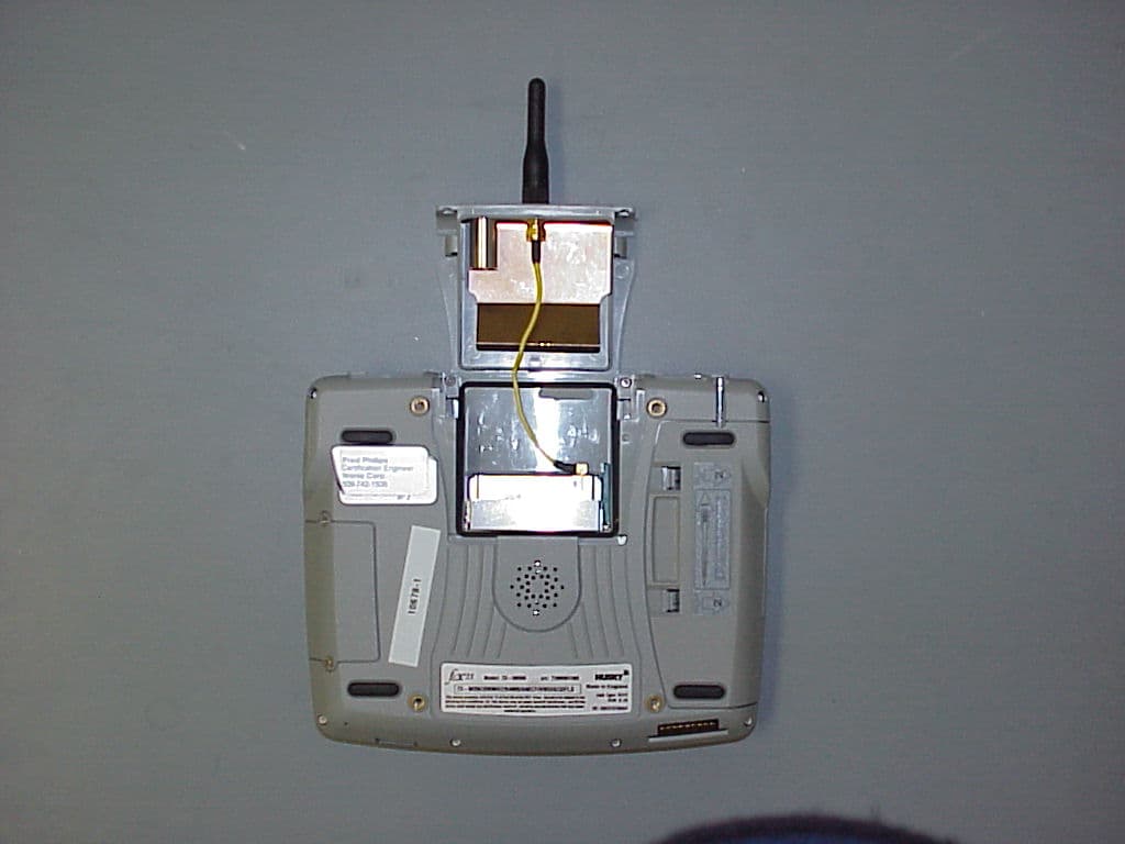
Click to zoom
Application Details
- Equipment Class
- PCT - PCS Licensed Transmitter worn on body
- Date of Grant
- Feb 05, 2003
- Application Purpose
- Original Equipment
- Date of Application
- Feb 05, 2003
- Equipment Note
- Handheld PC with GSM Card
- Frequency Range
- 1850.20000000 - 1909.80000000
- Country
- United States
Documents & Files
Document Text
Text extracted from the exhibit documents filed with the FCC. Open a document above to read the original.
Users Manual
© Copyright 2002 Itronix CorporationAll Rights ReservedThe information stored in this document is copyright and may not bereproduced, stored in a retrieval system in any form or by any means,electronic, mechanical, photocopying or otherwise, without prior permissionfrom the copyright holder, Itronix Corporation.While every precaution has been taken in the preparation of this document, thepublisher assumes no responsibility for errors and omissions, nor is any liabilityassumed for damage resulting from the use of the information contained withinthis document.Itronix Corporation801 South Stevens StreetSpokaneWashington 99204USATelephone: +1 509 624 6600 Facsimile: +1 509 626 4203 Email: [email protected] Web: http://www.itronix.com fex21 are trademarks of Itronix Corporation. Microsoft and Windows are trademarks of Microsoft Corporation in the U.S.A. and/or other countries.SoftModem is Copyright 1993-1999, AltoCom Inc. All rights reserved Any other trademarks used in this booklet are acknowledged.Document No. 75-0100-001 Electromagnetic Compatibility CAUTION!Approved accessories only may be used with this equipment. In general, all cables must be high quality,shielded, correctly terminated and normally restricted to 2 meters in length. Itronix AC Adaptors employspecial provisions to avoid radio interference and should not be altered or substituted.Unapproved modifications or operations beyond or in conflict with these instructions for use may voidauthorization by the authorities to operate the equipment.EuropeThis product complies with the radio interference protection requirements of the Council Directive 89/336/ECon the approximation of the laws of the Member States of the European Union relating to electromagneticcompatibility. The product was tested in a typical configuration and found to conform to the following testspecifications:EN55022 Radiated and conducted emissions, Class B. EN50082 or EN55024 ESD and radiated and conducted immunity.For further compliance details, refer to the specific CE Declaration Of Conformity. This is available on request,please quote the exact and full model number for the product(s) in question.USARADIO INTERFERENCE, FCC StatementNOTE : This equipment has been tested and found to comply with the limits for a Class B digital device, pursuant to Part 15 of the FCC Rules. These limits are designed to provide reasonable protection againstharmful interference in a residential installation. This equipment generates, uses, and can radiate radiofrequency energy and, if not installed and used in accordance with the instructions, may cause harmfulinterference to radio communications. However, there is no guarantee that interference will not occur in aparticular installation. If this equipment does cause harmful interference to radio or television reception, whichcan be determined by turning the equipment off and on, the user is encouraged to try to correct theinterference by one or more of the following measures: • Reorient or relocate the receiving antenna • Increase the separation between the equipment and the receiver. • Connect the equipment to an outlet on a circuit different from that to which the receiver is connected. • Consult the dealer or an experienced radio/TV technician for help. CanadaEnglishThis digital apparatus does not exceed class B limits for radio noise emissions from digital apparatus set out inthe Radio Interference Regulations of the Canadian Department of Communications, standard ICES-003.FrançaisAvis de conformité aux normes du Ministère des Communications du Canada.Le présent appareil numérique n’émet pas de bruits radioélectriques dépassant les limites applicable auxappareils numériques de classe B préscrites dans le Règlement sur le brouillage radioélectrique édicté par leMinistère des Communications du Canada, NMB-003.26 Contents The Other Guides 1 Setting Up 2 Fitting the battery pack 2 Switching the unit on 3 Calibrating the touch screen 3 Setting the time and date 4 Recording your personal information 4 Controls 4 How to use the pen 5 How to adjust the screen contrast 5 How to use the screen backlight 5 How to enter data 6 How to move the cursor 6 How to reset your Itronix fex21 7 Batteries 8 How to check the charge level of Li-Ion batteries 9 How to charge the battery 10 How to replace the battery pack 11 How to replace Alkaline batteries 12 Distribution and Battery management 12 Battery Storage 13 Looking after your fex21 14 Cleaning your fex21 14 Using your fex21 safely 15 Backstrap 15 CompactFlash and PC Cards 16 Using CompactFlash cards 16 Using Type II and Type III PC Cards 18 Using Wireless Communications 20 Peripherals 21 Troubleshooting 21 AC Power Adaptor 22 Additional instructions for the 12V dc power cable 22 Additional instructions for the 24V vehicle battery converter 23 Modem 24 European Modem Only (CTR21) 24 USA Modem Only (FCC part 68) 25 Electromagnetic Compatibility 26 i USA Modem Only (FCC part 68)ANALOG DEVICE WARNINGSThis equipment complies with Part 68 of the Federal Communications Commission(FCC) rules for the United States.A label is located on the underside of the base unit containing the registrationnumber and Ringer Equivalence Number (REN). You must upon request providethe following information to your local telephone company:USOC Jack Type: RJ-11 REN: 0.8 Should you experience trouble with this telephone equipment, please contactItronix - contact addresses are listed on the back cover of this booklet.The REN is used to determine the quantity of devices, which may be connected tothe telephone line. Excessive REN’s on the telephone line may result in the devicesnot ringing in response to an incoming call. In most, but not all, areas, the sum ofRENs should not exceed five (5.0). To be certain of the number of devices that maybe connected to a line, as determined by the total REN’s, contact the localtelephone company.If you have problems with your Itronix fex21 modem, contact Itronix for repair andwar…
Text truncated - open the document above for the full version.
Attestation Statements
Federal Communication Commission Equipment Authorization Division, Application Processing Branch 7435 Oakland Mills Road Columbia, MD 21048 January 17, 2003 TO WHOM IT MAY CONCERN, Regarding: FCC ID: Title/Model: KBCIX110A750 Fex21 & GoBook H206 The test reports, included in this submittal, describe testing performed on the GoBook H206. Preliminary testing performed on the Fex21 and the H206 showed that the H206 was the ‘worst case’ of the two models listed in this submittal. If you have any questions, please feel free to contact me at the address shown below. Sincerely, Pete Krebill Engineer Cetecom Inc. 411 Dixon Landing Rd. Milpitas, CA 95035 (408) 586-6200
Cover Letter(s)
Federal Communication Commission Equipment Authorization Division, Application Processing Branch 7435 Oakland Mills Road Columbia, MD 21048 January 17, 2003 TO WHOM IT MAY CONCERN, Pursuant to Paragraphs §0.457 and 0.459 of the Commission’s Rules (47 C.F.R.) and Section §552(b)(4) of the Freedom of Information Act, Itronix Corporation requests confidentiality for the following products: FCC ID: Title/Model: KBCIX110A750 Fex21 & GoBook H206 For the product stated above, we request that the following information be held confidential: 1) Electrical Schematics of the Circuitry 2) Block diagram 3) Tune-up information 4) Operational descriptions No other items submitted as part of the equipment authorization filing process are deemed confidential. The above exhibits contain Itronix Corporation trade secrets and proprietary information that could be of benefit to our competitors regarding the design of our mobile handset. This material is not customarily available to the general public and we request that it be withheld from public inspection. If you have any questions, please feel free to contact me at the address shown below. Sincerely, Pete Krebill Engineer Cetecom Inc. 411 Dixon Landing Rd. Milpitas, CA 95035 (408) 586-6200
External Photos
EUT Front EUT Back
RF Exposure Info
SAR Test Report No : SAR_336_2002_FCC_1900 Date of Report: 01/16/2003 Appendix A Page 1 of 3 Appendix A: Measurement Plots Plot 1. Date: 01/03/2003 Temperature Air / Liquid: 20.4°C / 21.6°C Liquid mass density (ρ): 1 DCP 1 X=9, Y=13.6, Z=8.7 Probe S/N:0123 Air Factor X=346, Y=318, Z=386 Probe S/N:0123 liquid/air conversion Factor 0.610 Simulated tissue dielectric parameters: ε r :53.35 σ: 1.563 Channel / Frequency 512 / 1850.2 MHz Maximum 1 gram SAR 1 timeslot: 0.279W/Kg Maximum 10 gram SAR 1 timeslot: 0.179W/Kg Power reference start: 0.097W/Kg Power reference end 0.097W/Kg Power reference change 2 -0.00% 1 DCP: Diode compression potential for different types of modulation is determined during the calibration of the probe. See section 6.2 of this report Probe and Amplifier Specification. Crest factor is not used. 2 The power reference change is calculated by the test system with more digits than indicated in the power reference start and end values. SAR Test Report No : SAR_336_2002_FCC_1900 Date of Report: 01/16/2003 Appendix A Page 2 of 3 Plot 2. Date: 01/03/2003 Temperature Air / Liquid: 20.4°C / 21.6°C Liquid mass density (ρ): 1 DCP 1 X=9, Y=13.6, Z=8.7 Probe S/N:0123 Air Factor X=346, Y=318, Z=386 Probe S/N:0123 liquid/air conversion Factor 0.610 Simulated tissue dielectric parameters: ε r :53.16 σ: 1.576 Channel / Frequency 661 / 1880 MHz Maximum 1 gram SAR 1 timeslot: 0.224W/Kg Maximum 10 gram SAR1 timeslot : 0.143W/Kg Power reference start: 0.080W/Kg Power reference end 0.080W/Kg Power reference change 2 -0.00% 1 DCP: Diode compression potential for different types of modulation is determined during the calibration of the probe. See section 6.2 of this report Probe and Amplifier Specification. Crest factor is not used. 2 The power reference change is calculated by the test system with more digits than indicated in the power reference start and end values. SAR Test Report No : SAR_336_2002_FCC_1900 Date of Report: 01/16/2003 Appendix A Page 3 of 3 Plot 3. Date: 01/03/2003 Temperature Air / Liquid: 20.4°C / 21.6°C Liquid mass density (ρ): 1 DCP 1 X=9, Y=13.6, Z=8.7 Probe S/N:0123 Air Factor X=346, Y=318, Z=386 Probe S/N:0123 liquid/air conversion Factor 0.610 Simulated tissue dielectric parameters: ε r :52.96 σ: 1.58 Channel / Frequency 810 / 1909.8 MHz Maximum 1 gram SAR 1 timeslot: 0.207W/Kg Maximum 10 gram SAR 1 timeslot : 0.134W/Kg Power reference start: 0.070W/Kg Power reference end 0.071W/Kg Power reference change 2 1.92% 1 DCP: Diode compression potential for different types of modulation is determined during the calibration of the probe. See section 6.2 of this report Probe and Amplifier Specification. Crest factor is not used. 2 The power reference change is calculated by the test system with more digits than indicated in the power reference start and end values.
RF Exposure Info
SAR Test Report No.: SAR_336_2002_FCC_1900 Date of Report:01/16/2003 Appendix B Page 1 of 5 Appendix B: Photos EUT Photos Photo 1. EUT top SAR Test Report No.: SAR_336_2002_FCC_1900 Date of Report:01/16/2003 Appendix B Page 2 of 5 Photo 2. EUT bottom SAR Test Report No.: SAR_336_2002_FCC_1900 Date of Report:01/16/2003 Appendix B Page 3 of 5 Setup Photos Photo 3. Body SAR setup SAR Test Report No.: SAR_336_2002_FCC_1900 Date of Report:01/16/2003 Appendix B Page 4 of 5 Photo 4. Body SAR distance SAR Test Report No.: SAR_336_2002_FCC_1900 Date of Report:01/16/2003 Appendix B Page 5 of 5 Photo 5. Photo to demonstrate 15 cm Z-axis flat phantom
RF Exposure Info
SAR Test Report No : SAR_336_2002_FCC_1900 Date of Report: 01/16/2003 Appendix C Page 1 of 30 Tissue Parameters 1900MHz Head liquid: Recipe: The following recipe is provided in percentage by weight. 54.9% distilled water 44.92% DGBE 0.18% salt 0.1% bactericide Di-electric constants measured on 01/03/03: 01/03/2003 Freq. Rel. Condy (MHz) Perm. (S/m) 1900 38.52 1.448 1900MHz Body Liquid: Recipe: The following recipe is provided in percentage by weight. 69.17% distilled water 30.29% DGBE 0.44% salt 0.1% bactericide Di-electric constants measured on 01/03/03: 01/03/2003 Freq. Rel. Condy (MHz) Perm. (S/m) 1850.2 53.35 1.563 1880 53.16 1.576 1909.8 52.96 1.58 Conductivity 1.4 1.45 1.5 1.55 1.6 1.65 1850187018901910 frequency (MHz) conductivity (S/m) 1900Body liquid 1528 std +5% -5% Permittivity 49 50 51 52 53 54 55 56 57 1850187018901910 frequency (MHz) relative permittivity 1900Body liquid 1528 std +5% -5% Environment 01/03/2003: Temperature: 20.2 °C – 21.4°C Humidity: 45% _ 55 % SAR Test Report No : SAR_336_2002_FCC_1900 Date of Report: 01/16/2003 Appendix C Page 2 of 30 Test Equipment Test Equipment Model Serial Instrument description Supplier/Manufacturer Model Serial No. Calibration (date) Bench top Robot Mitsubishi supplied by Indexsar RV-E2 Serial No. N/A SAM Phantom Upright shell phantom made by Antennessa digitized and mounted by Indexsar SAM 04/02 FT08 N/A 1900MHz Head Tissue Simulant Cetecom Inc. 1900 Head N/A 01/03/2003 1900MHz Body Tissue Simulant Cetecom Inc. 1900 Body N/A 01/03/2003 1900MHz Dipole IndexSAR – IEEE 1528 design IXD-190 0016 07/30/2002 Netwok Analyzer Agilent 8753ES US39172511 04/04/2002 RF Amplifier Vectawave N/A N/A N/A Power Meter Rohde and Schwartz NRVD 836875/020 5/2002 Power Sensor Rohde and Schwartz URV5-Z2 836029/034 5/2002- Power Sensor Rohde and Schwartz URV5-Z2 836029/035 5/2002- SAR Probe IndexSAR IXP-050 S/N 0123 10/25/2002 Probe amplifier Indexsar IXA-010 S/N 043 N/A Thermometer Control Company 4039 20410549 11/20/2001 SAR Test Report No : SAR_336_2002_FCC_1900 Date of Report: 01/16/2003 Appendix C Page 3 of 30 IMMERSIBLE SAR PROBE CALIBRATION REPORT Part Number: IXP – 050 S/N 0123 25 th October 2002 Indexsar Limited Oakfield House Cudworth Lane Newdigate Surrey RH5 5DR Tel: +44 (0) 1306 631 233 Fax: +44 (0) 1306 631 834 e-mail: [email protected] SAR Test Report No : SAR_336_2002_FCC_1900 Date of Report: 01/16/2003 Appendix C Page 4 of 30 INTRODUCTION This Report presents measured calibration data for a particular Indexsar SAR probe (S/N 0123) and describes the procedures used for characterisation and calibration. Indexsar probes are characterised using procedures that, where applicable, follow the recommendations of CENELEC [1] and IEEE [2] standards. The procedures incorporate techniques for probe linearisation, isotropy assessment and determination of liquid factors (conversion factors). Calibrations are determined by comparing probe readings with analytical computations in canonical test geometries (waveguides) using normalised power inputs. Each step of the calibration procedure and the equipment used is described in the sections below. CALIBRATION PROCEDURE 1. Equipment Used For the first part of the characterisation procedure, the probe is placed in an isotropy measurement jig as pictured in Figure 1. In this position the probe can be rotated about its axis by a non-metallic belt driven by a stepper motor. The probe is attached via its amplifier and an optical cable to a PC. A schematic representation of the test geometry is illustrated in Figure 2. A balanced dipole (900 MHz) is inserted horizontally into the bracket attached to a second belt (Figure 1). The dipole can also be rotated about its axis. A cable connects the dipole to a signal generator, via a directional coupler and power meter. The signal generator feeds an RF amplifier at constant power, the output of which is monitored using the power meter. The probe is positioned so that its sensors line up with the rotation center of the source dipole. By recording output voltage measurements of each channel as both the probe and the dipole are rotated, data are obtained from which the spherical isotropy of the probe can be optimised and its magnitude determined. The calibration process requires E-field measurements to be taken in air, in 900 MHz simulated brain liquid and at other frequencies/liquids as appropriate. 2. Linearising probe output The probe channel output signals are linearised in the manner set out in Refs [1] and [2]. The following equation is utilized for each channel: U lin = U o/p + U o/p 2 / DCP (1) SAR Test Report No : SAR_336_2002_FCC_1900 Date of Report: 01/16/2003 Appendix C Page 5 of 30 where U lin is the linearised signal, U o/p is the raw output signal in voltage units and DCP is the diode compression potential in similar voltage units. DCP is determined from fitting equation (1) to measurements of U lin versus source feed power over the full dynamic range of the probe. The DCP is a characteristic of the schottky diodes used as the sensors. For the IXP-050 probes with CW signals the DCP values are typically 0.10V (or 20 in the voltage units used by Indexsar software, which are V*200). 3. Selecting channel sensitivity factors to optimise isotropic response The basic measurements obtained using the calibration jig (Fig 1) represent the output from each diode sensor as a function of the presentation angle of the source (probe and dipole rotation angles). The directionality of the orthogonally-arranged sensors can be checked by analysing the data using dedicated Indexsar software, which displays the data in 3D format as in Figure 3. The left-hand side of this diagram shows the individual channel outputs after linearisation (see above). The program uses these data to balance the channel outputs and then applies an optimisation process, which makes fine adjustments to the channel factors for optimum isotropic response. The next stage of the process is to calibrate t…
Text truncated - open the document above for the full version.
RF Exposure Info
CETECOM Inc. 411 Dixon Landing Road Milpitas, CA 95035 U.S.A. Phone: + 1 (408) 586 6200 Fax: + 1 (408) 586 6299 E-mail: [email protected] http://www.cetecom.com CETECOM Inc. is a Delaware Corporation with Corporation number: 2113686 Board of Directors: Dr. Harald Ansorge, Dr. Klaus Matkey, Hans Peter May V.2.16M-2002-03-12 f:\emc\projects\sierra_wireless\336-2002_fex21\sar\report\sar_336_2002_fcc_1900.doc © Copyright by CETECOM SAR Test Report No. SAR_336_2002_FCC_1900 for the Itronix Corporation Fex21 and GoBook H206 1850 MHz to 1910MHz Handheld Computer Model Number: Fex21 and IX110 FCC ID: KBCIX110AC750 Date of Report: 01/16/2003 Date of issue: 01/16/2003 Report Copy No.: 01 SAR Test Report No. SAR_336_2002_FCC_1900 Date of Report: 01/16/2003 Page 2 of 27 V.2.16M-2002-03-12 This report shall not be reproduced except in full without the written approval of: CETECOM Inc. SAR 411 Dixon Landing Road Milpitas, CA 95035 U.S.A. Contents 1. ASSESSMENT ...................................................................................................................4 2. ADMINISTRATIVE DATA...................................................................................................5 2.1. Identification of the Testing Laboratory Issuing the SAR Assessment Report ...............5 2.2. Identification of the Client...........................................................................................5 2.3. Identification of the Manufacturer...............................................................................5 3. EQUIPMENT UNDER INVESTIGATION (EUI)...................................................................6 3.1. Identification of the Equipment under Investigation ...................................................6 3.2. Front View of the Equipment under Investigation ......................................................7 4. SUBJECT OF INVESTIGATION ........................................................................................8 4.1. The IEEE Standard C95.1 and the FCC Exposure Criteria .......................................8 4.2. Distinction Between Exposed Population, Duration of Exposure and Frequencies...8 4.3. Distinction between Maximum Permissible Exposure and SAR Limits......................9 4.4. SAR Limit ...................................................................................................................9 5. THE FCC MEASUREMENT PROCEDURE .....................................................................10 5.1. General Requirements.............................................................................................10 5.2. Device Operating Next to a Person’s Ear ................................................................10 5.3. Test Positions ..........................................................................................................11 5.4. Test positions of device relative to head..................................................................11 5.5. Test to be Performed ...............................................................................................14 5.6. Body-worn and Other Configurations.......................................................................14 5.7. Procedure for assessing the peak spatial-average SAR .........................................15 5.8. Determination of the largest peak spatial-average SAR ..........................................17 6. THE MEASUREMENT SYSTEM ......................................................................................18 6.1. Robot system specification ......................................................................................18 6.2. Probe and amplifier specification .............................................................................19 6.3. Phantoms.................................................................................................................19 6.4. SAR measurement procedure .................................................................................20 SAR Test Report No. SAR_336_2002_FCC_1900 Date of Report: 01/16/2003 Page 3 of 27 V.2.16M-2002-03-12 This report shall not be reproduced except in full without the written approval of: CETECOM Inc. SAR 411 Dixon Landing Road Milpitas, CA 95035 U.S.A. 6.5. SARA2 Interpolation and Extrapolation schemes ....................................................20 6.6. Interpolation of 2D area scan...................................................................................21 6.7. Extrapolation of 3D scan..........................................................................................21 6.8. Interpolation of 3D scan and volume averaging.......................................................21 7. UNCERTAINTY ASSESSMENT.......................................................................................23 7.1. Measurement Uncertainty Budget ...........................................................................24 8. TEST RESULTS SUMMARY............................................................................................25 8.1. Conducted Output Power.........................................................................................25 8.2. Body SAR results for GSM 1900MHz band for Fex21 and GoBook H206 ..............25 8.3. Validation Check Results .........................................................................................26 9. REFERENCES..................................................................................................................27 SAR Test Report No. SAR_336_2002_FCC_1900 Date of Report: 01/16/2003 Page 4 of 27 V.2.16M-2002-03-12 This report shall not be reproduced except in full without the written approval of: CETECOM Inc. SAR 411 Dixon Landing Road Milpitas, CA 95035 U.S.A. 1. Assessment The Itronix Corporation Fex21 and GoBook H206 Handheld Computer is in compliance with the exposure criteria specified in Federal Communications Commission (FCC) Guide…
Text truncated - open the document above for the full version.
Test Report
CETECOM Inc. CETECOM Inc. 411 Dixon Landing Road, Milpitas, CA-95035, USA Phone: +1 408 586 6200 Fax: +1 408 586 6299 www.cetecom.com Issued test report consists of 57 Pages Page 1 (57) Test report no.: EMC_336_FCC24_2002 FCC Part 24 / RSS 133 (Model: IX110, Marketing Name: GoBook H206) FCC ID: KBCIX110AC750 FCC LISTED, REG. NO.: 101450 & RECOGNIZED BY INDUSTRY CANADA IC – 3925 CETECOM Inc. Test report no.: EMC_336_FCC24_2002 Issue date: 2002-12-03 Page 2 (57) Table of Contents 1 General information 1.1 Notes 1.2 Testing laboratory 1.3 Details of applicant 1.4 Application details 1.5 Test item 1.6 Test standards 2 Technical test 2.1 Summary of test results 2.2 Test report 1 General information 1.1 Notes The test results of this test report relate exclusively to the test item specified in 1.5. The CETECOM Inc. does not assume responsibility for any conclusions and generalisations drawn from the test results with regard to other specimens or samples of the type of the equipment represented by the test item. The test report may only be reproduced or published in full. Reproduction or publication of extracts from the report requires the prior written approval of the CETECOM Inc. TEST REPORT PREPARED BY: EMC Engineer: Mark Sechrist 1.2 Testing laboratory CETECOM Inc. 411 Dixon Landing Road, Milpitas, CA-95035, USA Phone: +1 408 586 6200 Fax: +1 408 586 6299 E-mail: [email protected] Internet: www.cetecom.com CETECOM Inc. Test report no.: EMC_336_FCC24_2002 Issue date: 2002-12-03 Page 3 (57) 1.3 Details of applicant Name : Itronix Corporation Street : 804 South Stevens St. City / Zip Code : Spokane, WA 99204 Country : USA Contact : Mr. Richard Sargent Telephone : (509) 742-1253 Tele-fax : (509) 742-1672 e-mail : [email protected] 1.4 Application details Date of receipt of application : 9/30/02 Date of receipt test item : 9/30/02 Date of test : 11/8/01 to 11/20/01 (AirCard 750 GSM card); 11/11/02 (GoBook H206) 1.5 Test item Manufacturer : Itronix Corporation Marketing Name GoBook H206 Model No. : IX110 Description : Handheld computer with triband 900/1800/1900 GSM card FCC-ID : KBCIX110AC750 Additional information Frequency : GSM 900/1800/1900 Type of modulation : GMSK Number of channels : 299 (in PCS 1900) Antenna : Whip Monopole Power supply : 5.0 VDC Output power : 31.4dBm (1.38W) max. EIRP Extreme vol. Limits : 4.5 VDC to 5.5 VDC Extreme temp. Tolerance : -10ºC to 50ºC 1.6 Test standards FCC Part 24 / RSS133 r1 CETECOM Inc. Test report no.: EMC_336_FCC24_2002 Issue date: 2002-12-03 Page 4 (57) 2 Technical test 2.1 Summary of test results No deviations from the technical specification(s) were ascertained in the course of the tests Performed Final Verdict: (only “passed” if all single measurements are “passed”) Passed Technical responsibility for area of testing: 2002-12-10 EMC & Radio Lothar Schmidt (Technical Manager) Date Section Name Signature Responsible for test report and project leader: 2002-12-10 EMC & Radio Mark Sechrist (EMC Engineer) Date Section Name Signature CETECOM Inc. Test report no.: EMC_336_FCC24_2002 Issue date: 2002-12-03 Page 5 (57) 2.2 Test report TEST REPORT Test report no.: EMC_336_FCC24_2002 (GoBook H206) CETECOM Inc. Test report no.: EMC_336_FCC24_2002 Issue date: 2002-12-03 Page 6 (57) TEST REPORT REFERENCE POWER OUTPUT SUBCLAUSE § 24.232 ............................................................................................. 7 FREQUENCY STABILITY SUBCLAUSE § 24.235 ............................................................................. 12 OCCUPIED BANDWIDTH §2.989 ........................................................................................................ 14 EMISSIONS LIMITS §24.238 ............................................................................................................... 21 RECEIVER RADIATED EMISSIONS SUBCLAUSE § 15.209........................................................... 40 CONDUCTED SPURIOUS EMISSIONS SUBCLAUSE § 24.238 ........................................................ 45 CONDUCTED EMISSIONS § 15.107/207 ............................................................................................. 54 TEST EQUIPMENT AND ANCILLARIES USED FOR TESTS ............................................................... 55 BLOCK DIAGRAMS ...................................................................................................................................... 56 CETECOM Inc. Test report no.: EMC_336_FCC24_2002 Issue date: 2002-12-03 Page 7 (57) POWER OUTPUT SUBCLAUSE § 24.232 Summary: During the process of testing, the EUT was controlled via Rhode & Schwarz Digital Radio Communication tester (CMD-55) to ensure max. power transmission and proper modulation. This paragraph contains both average, peak output powers and EIRP measurements for the EUT. In all cases, the peak output power is within the specified limits. Method of Measurements: The EUT was set up for the max. output power with pseudo random data modulation. The power was measured with R&S Spectrum Analyzer ESIB 40 ( peak) and NRVD power meter (average) These measurements were done at 3 frequencies, 1850.2 MHz, 1880.0 MHz and 1909.8 MHz (bottom, middle and top of operational frequency range) Limits: Power Step Nominal Peak Output Power (dBm) Tolerance (dB) 0 +30 ± 2 Power Measurements: Conducted: Frequency (MHz) Power Step Peak Output Power (dBm) Average Output Power during burst (dBm) 1850.2 0 28.02 dBm 18.78 dBm 1880.0 0 27.64 dBm 18.49 dBm 1909.8 0 27.77 dBm 18.53 dBm Measurement uncertainty ±0.5 dB ANALYZER SETTINGS: RBW = 3MHz VBW = 3MHz CETECOM Inc. Test report no.: EMC_336_FCC24_2002 Issue date: 2002-12-03 Page 8 (57) EIRP Measurements Description: This is the test for the maximum radiated power from the EUT. Rule Part 24.232(b) specifies that "Mobile/portable stations are limited to 2 watts e.i.r.p. peak power" and 24.232(c) specifies that "Peak transmit power must be measured over any interval of continuous transmission using…
Text truncated - open the document above for the full version.
Contact Information
Applicant
Ray Garcia(Agency Manager)
Test Firm
Cetecom Inc.Lothar Schmidt
Technical Specifications
| # | Rule Parts | Frequency Range | Power Output | Emission | Tolerance |
|---|---|---|---|---|---|
| 1 | 24E | 1.85 GHz - 1.91 GHz | 1.38 W | 281KGXW | 0.0400000000 ppm |
Other Applications from General Dynamics Itronix Corporation

KBCIX-BR-51
Jan 20, 2008IX-BTBR51
Equipment Class
DSS - Part 15 Spread Spectrum Transmitter
KBCIX-MC8775
May 30, 2007IX-MC8775
Equipment Class
PCB - PCS Licensed Transmitter
KBCIX-4965AGN
May 21, 2007IX-4965AGN
Equipment Class
NII - Unlicensed National Information Infrastructure TX
KBCIX-AC595
Apr 19, 2007IX-AC595 DUAL-BAND CDMA/EV-DO PCMCIA MODEM CARD
Equipment Class
PCB - PCS Licensed Transmitter
KBCIX-NW620
Mar 13, 2007IX-NW620 CDMA/EV-DO
Equipment Class
PCB - PCS Licensed Transmitter