KBCIX260MPIAC860LAPTOP PC W/WLAN & DUALBAND GSM/ GPRS/ EDGE/WCDMA
General Dynamics Itronix Corporation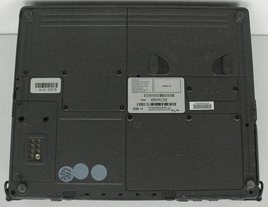
Click to zoom
Application Details
- Equipment Class
- DTS - Digital Transmission System
- Date of Grant
- Sep 14, 2006
- Application Purpose
- Original Equipment
- Date of Application
- Sep 13, 2006
- Equipment Note
- LAPTOP PC W/WLAN & DUALBAND GSM/ GPRS/ EDGE/WCDMA
- Frequency Range
- 2412.00000000 - 2462.00000000
- Country
- United States
Documents & Files
Document Text
Text extracted from the exhibit documents filed with the FCC. Open a document above to read the original.
Users Manual
Radio Specific Safety Information Identification GoBook IX260 Copyright Notice © Copyright 2006. All rights reserved. No part of this document may be reproduced, transmitted, transcribed, stored in a retrieval system, or translated into any other language or computer language in whole or in part, in any form or by any means, whether it be electronic, mechanical, magnetic, optical, manual, or otherwise, without the prior written consent of Itronix Corporation, 12825 E. Mirabeau Parkway, Spokane Valley, WA 99216. Disclaimer Itronix Corporation reserves the right to revise the manual and make periodic changes to the content without a direct or inferred obligation to notify any person of such revision or changes. Itronix Corporation does not assume responsibility for the use of this help manual, nor for any patent infringements or other rights or third parties who may use the manual. This document contains valuable trade secrets and proprietary information of Itronix Corporation. This product is available for purchase under Itronix's standard terms and conditions of sale. Hardware products may be reconditioned, or be manufactured from parts and components that may be new, used, rebuilt, or recycled and in some cases, the hardware product may not be new and may have been previously installed. In any event, Itronix warranty terms apply. Warnings and Cautions WARNING It is important that only authorized personnel service and attempt repairs on the equipment. Unauthorized service or repair may void the warranty and any maintenance contract in effect for the equipment. Unauthorized service personnel might be subject to shock hazard on some equipment if removal of protective covers is attempted. Internal radio(s) may have an individual FCC Identifier which are not applicable to this configuration. FCC Identifiers: KBCIX260MPIAC860 on the bottom of the IX260 Laptop PC are applicable. The Radios in the IX260 Laptop PC must not be co-located or operating in conjunction with any other antenna or transmitter than specified in the above referenced FCC Certification filings . Safety Information This device contains a WLAN radio transmitter and a WAN radio transmitter. To comply with FCC RF exposure requirements when using the WAN radio transmitter, a minimum separation distance of 20 cm must be maintained between the upper right edge of the display screen antenna and all users/bystanders. When using the WLAN transmitter, a minimum separation distance of 20 cm must be maintained between the upper right and left edges of the display screen and all users/bystanders. The WAN transmitter and WLAN transmitter should be turned off before carrying the Laptop PC in order to comply with FCC RF exposure requirements Do not proceed beyond a WARNING or CAUTION until the indicated conditions are fully understood and met.
Users Manual
Getting Started Congratulations on your purchase of the Itronix GoBook III computer! Your new GoBook III features the most innovative advances in portable computing technology. It combines state-of-the-art ergonomics with a rugged, durable architecture to provide you with a notebook computer that is compact, powerful, rugged and easy to use. Designed for a wide range of business and personal productivity applications, the GoBook III is an ideal choice for use in applications that require durability and performance. For maximum expandability without compromising portability, the GoBook III has a USB interface and aPC card slot. The high capacity hard disk drive provides you with plenty of storage space for multimedia files and applications. The GoBook III features a standard 87-key Nitevue® keyboard (89-key international). The high- resolution 12.1-inch touch screen LCD panel provides clear and crisp viewing with the convenience of a touch screen. This online document, GoBook III Help , contains all the information you need to set up and use your new GoBook III. It describes all the features of the GoBook III in an easy-to-read yet thorough manner. For information on printing, navigating or otherwise using GoBook III Help see How to Use This Help System. GoBook III ® Help Page 1 of 80GoBook III Help 7/5/2004file://C:\Documents%20and%20Settings\harwoodm.ITRXNT1\Local%20Settings\Temp\~h... Checklists After opening the package, carefully inspect the contents. Contact your dealer if any items are missing or appear damaged. The shipping carton should contain the following: STANDARD z The Itronix GoBook III computer z Battery z ADP-90AB or ADP-75FB AC adapter with power cord z 12.1 inch XGA display z Stylus z Shoulder Strap z GoBook III Quick Start Guide OPTIONS The following items are normally optional, but some vendors may include them in the standard package. Some items may not be available in some countries, or some vendors may choose not to carry all the items. z Floppy disk drive z CD-ROM drive z CD-RW Drive z DVD-ROM drive z Soft Handle z Media Bay Li-Ion battery pack z Hard Disk Drive Heater z LCD Heater CAUTION When purchasing any of the accessories listed above, purchase only those accessories that are approved for use with your computer. The above accessories are proprietary items. Your system vendor can obtain these approved accessories. If you use items that are not approved for use with this computer, you may cause your computer to malfunction, or to emit or receive electromagnetic radiation in excess of local regulations. For non-proprietary accessories such as PC Cards or printers, ensure that the accessor y functions properly in your computer before making the purchase. Your system vendor Page 2 of 80GoBook III Help 7/5/2004file://C:\Documents%20and%20Settings\harwoodm.ITRXNT1\Local%20Settings\Temp\~h... may be able to recommend reliable brands and models. Features High Capacity Hard Disk Drive The computer has a high capacity hard disk drive, enabling you to install your favorite programs and store large multimedia files. Full Array of Ports and Connectors Your computer includes standard ports for connecting to peripherals such as USB devices and monitors. USB ports allow you to add many types of peripherals. Large XGA LCD Your computer has a large, easy to view XGA LCD panel. Built-in Microphone and Stereo Speakers The stereo speakers and internal microphone enable you to run a variety of multimedia applications. Function Keys Function keys allow you to suspend your computer, shut the LCDs off, and give you easy control of audio and your monitor. Where to Look For Information About Your Computer This Help System describes the key elements of your computer. New users can find a simple step-by- step orientation in this chapter. About Windows For more extensive information and help about Windows go to Help and Support, found on the Start Menu. 72_0119_001 28 June 2004 © 2004 Itronix Corporation. All rights reserved. Page 3 of 80GoBook III Help 7/5/2004file://C:\Documents%20and%20Settings\harwoodm.ITRXNT1\Local%20Settings\Temp\~h... Precautions You can use your computer under a wide range of environmental conditions. However, to ensure long use and continued high performance, consider the following factors when setting up your computer: z Follow all warnings and instructions noted in this documentation and in Windows Help and Support, found on the Start Menu. z The first time you use your computer, we recommend that you carefully read the section on Power Management to familiarize yourself with some basic battery information and to ensure optimum performance z There is danger of explosion if the battery is incorrectly replaced. Replace only with the same or equivalent type recommended by the manufacturer. Dispose of used batteries according to the manufacturer's instructions. z Do not open the RAM door by yourself. z Unplug the computer from the power outlet before cleaning. Use a damp cloth for cleaning. Do not use aerosols, solvents, or strong detergents z Slots and openings in the computer case are for ventilation purposes. Do not block or cover these openings or the system could overheat z On the bottom of the GoBook III, there is a label with information on the power requirements of this system. These requirements must be followed. If you are unsure of your local power supply, consult your dealer or local Power Company z Do not step on or place anything on the power cord z If you use the computer with an extension cord, ensure that the total ampere ratings of all the devices sharing the extension do not exceed the rating of the extension cord or the rating of the wall outlet z Unless instructed, never push foreign objects into the computer through any of the slots or openings. Dangerous voltages are present, which could cause electric shock, fire, or damage sensitive components z For best results, use a power strip with a built-in surge protector. Do not use inferior extensi…
Text truncated - open the document above for the full version.
Cover Letter(s)
Cisco Systems, Inc. 4125 Highlander Parkway Richfield, Ohio 44286 Phone: 330 523-2094 Fax: 330 523-2002 http://www.cisco.com Phone: (330) 523-2094 Fax: (330) 523-2002 E-Mail: [email protected] September 12, 2006 Federal Communications Commission Equipment Authorization Division, Application Processing Branch 7435 Oakland Mills Road Columbia, MD 21046 Re: FCC ID: KBCIX260MPIAC860 To Whom It May Concern: The following information is to be held confidential pursuant to 47 CFR Part 0 §0.457 and Section 552(b)(4) of the Freedom of Information Act, because the information provided is proprietary and contains trade secrets. If made public, the information might be used to the disadvantage of the Cisco Systems, Inc. in the market place. Block Diagram Schematic Diagrams Technical Description Best Regards, Jim Nicholson EMC Compliance Engineer
Cover Letter(s)
209 Dayton Street, Suite 205 Edmonds, WA 98020-3581 425 771-4482 425 486-1933 Fax September 7, 2006 TIMCO ENGINEERING INC. 849 NW State Road 45 Newberry, Florida 32669 SUBJECT: FCC Certification of the Model: IX260 a Rugged Laptop PC with two embedded radios Grantee: ITRONIX, Corporation FCC ID: KBCIX260MPIAC860 1.) Part 15.247 - Compact Flash Module, IEEE 802.11(b), WLAN Module 2.) Part 22H & 24E. - PCMCIA, Type II Card, Dual-Band GSM/GPRS/EDGE/WCDMA/HSDPA/UMTS Composite Certification, RF Exposure category: Mobile, Co-located. Gentlemen: On behalf of ITRONIX, Corporation we request a composite Certification for the FCC ID: KBCIX260MPIAC860, a Rugged Laptop PC with two embedded co-located transmitters. This certification is requested to provide an FCC Identifier for this new composite co-located radio combination of two previously Certified individual transmitter modules. This filing is required to allow the addition of the new Model: AC860, WAN radio to the existing legacy IX260’s already deployed with the referenced embedded WLAN. We submit this application on behalf of Itronix Corporation for: 1.) Certification under Part 15.247, DTS, for the IX260 Rugged Laptop PC, with the embedded Cisco Systems, Inc. Model: MPI-350, a Direct Sequence Spread Spectrum Transmitter (DSSS), Compact Flash Module, Certified by the OEM under FCC ID: LDK102042. The maximum Conducted RF Power Output is: 21.2 dBm. 2.) Certification under Parts 22H and 24E for the IX260 Rugged Laptop PC, with the embedded Sierra Wireless, Inc. Model: AC860 Dual-band modem with GSM/GPRS/EDGE/WCDMA/HSDPA/UMTS in a PCMICA type II card, Certified by the OEM under, FCC ID: N7NAC860. Exhibits submitted in support of the two Form 731 applications for Certification here with include, agent authorization letter, request for confidentiality, separate EMC test reports for Parts 15 and Parts 22 & 24, EUT setup photos, OEM Conducted measurement test data, RF exposure (MPE) for each transmitter, FCC ID label and location, internal and external photographs, the user's manual and a Radio Specific RF Exposure warning statement. MPE calculations are submitted for each transmitter individually. The WAN and WLAN radios although co-located do not transmit at the same time. We will be referring to the original equipment manufacturers (OEM) Certification test data for the conducted measurements where appropriate. These two modules would be considered “identical” to the originally approved device as defined by Part 2.908. Confidential exhibits to be submitted directly to TIMCO by CISCO and Sierra Wireless should include block diagrams, schematic diagrams, operational description and parts list. I would gladly address any questions or comments you may have regarding these two applications for Certification. Best Regards, Rod Munro Agent for Itronix President, Spectrum Technology, Inc. [email protected]
Cover Letter(s)
From: Rod Munro [[email protected]] Sent: Tuesday, September 12, 2006 12:25 PM To: [email protected] Subject: FCC ID: KBCIX260MPIAC860, REF: JOB 2580UC6 TIMCO ENGINEERING INC. 849 NW State Road 45 Newberry, Florida 32669 Attention: Gretchen Torres & Bruno Clavier We offer the following responce to your comments from the email of September 10, 2006 pasted below. 1. The confidential exhibits have been requested from CISCO and should have been emailed directly to Bruno. 2. The radiated spurious is located in "Test Report 4" and the band-edge data above 2483.5 for the Rangestar PN: 100929, antenna is located in "Test Report 3". This antenna is not new and is the antenna approved in the original FCC ID: KBCIX260MPI as a stand alone, WLAN, and many more other Itronix co-located filings. For this specific filing the WAN radio is the "new" radio, the WLAN is the "old" existing radio in all of the thousands of older Models of IX600 now in the field. This is not a new laptop. This application is for one purpose; to allow co-location with the new WAN AC860. 3. The WLAN antenna is a Rangestar Wireless antenna Part Number: 100929. Antenna spec. sheet attached. 4. The OEM conducted report does show the 109 mW. However, when we measured the conducted power prior to the radiated spurious measurements the output power was measured at 132 mW. In Test Report 4 on page 3 the conducted power output data is reported for this application. At the time of the IX260MPI filing we measured the output from numerous MPI modules looking to stay within the +/- .5 dB. Based on the test results, we had no choice except to report the higher output power actually measured. If you refer to the original grant for the FCC ID: KBCIX260MPI you will find the output is listed as 132 mW as it is in the FCC ID's: KBCIX260MPIA555BT KBCIX260MPIA755BT and some other as well. ........................................................................................................................................................... ..................................................................................................................................................... 1. CONFIDENTIAL EXHIBITS: Please provide us with the following exhibits that have been requested to be marked as confidential- Block Diagram, Schematics, Operational Description, Parts List, Tune Up Info. Thanks. 2. Radiated spurious emissions: Please point out in filing radiated spurious emissions data (including band-edges data above 2483.5MHz) for the antenna(s) integrated into this laptop. Were these antennas already approved? Please explain compliance in this new laptop. 3. Please specify the type of antenna (model, type, etc.). Alternatively, please indicate location in filing. 4. The original OEM report and additional reports show a power of 109mW, whereas this filing is requested for 132mW. Please explain the power level inconsistency for compliance with 2.907(b), 2.908, 2.924, 2.927(b), 2.931, 2.932, 2.1043 etc. Where applicable, please revise test data that may be affected by this variation in power. The FCC will accept a +/-.5dB variation in conducted power for identical devices. ........................................................................................................................................................... ...................................................................................................................................................... I trust this may satisfy your concerns however, please just let me know if you might have any other comments and I will gladly address them. Best Regards, Rod Munro
External Photos
© 2002 Celltech Research Inc. ITRONIX CORPORATION FCC ID: KBCIX260MPI350 Rugged Laptop PC with Cisco MPI-350 Mini-PCI DSSS WLAN Card EXTERNAL EUT PHOTOGRAPHS © 2002 Celltech Research Inc. ITRONIX CORPORATION FCC ID: KBCIX260MPI350 Rugged Laptop PC with Cisco MPI-350 Mini-PCI DSSS WLAN Card EXTERNAL EUT PHOTOGRAPHS © 2002 Celltech Research Inc. ITRONIX CORPORATION FCC ID: KBCIX260MPI350 Rugged Laptop PC with Cisco MPI-350 Mini-PCI DSSS WLAN Card EXTERNAL EUT PHOTOGRAPHS © 2002 Celltech Research Inc. ITRONIX CORPORATION FCC ID: KBCIX260MPI350 Rugged Laptop PC with Cisco MPI-350 Mini-PCI DSSS WLAN Card EXTERNAL EUT PHOTOGRAPHS
ID Label/Location Info
Applicant: ITRONIX, Corp. FCC ID: KBCIX260MPIAC860 FCC ID label location on bottom of the PC The large silver label located right of center, between the RAM and BATTERY covers is the FCC Identifiers label location. I I I V The facsimile Part 15.19 compliance label is shown below. This compliance statement is located on the upper left corner of the photo above. (a black label) Exhibit 1
Internal Photos
© 2002 Celltech Research Inc. ITRONIX CORPORATION FCC ID: KBCIX260MPI350 Rugged Laptop PC with Cisco MPI-350 Mini-PCI DSSS WLAN Card INTERNAL EUT PHOTOGRAPHS Back Side of LCD Display Cover for Back of LCD Display Antenna Antenna © 2002 Celltech Research Inc. ITRONIX CORPORATION FCC ID: KBCIX260MPI350 Rugged Laptop PC with Cisco MPI-350 Mini-PCI DSSS WLAN Card INTERNAL EUT PHOTOGRAPHS Back Side of LCD Display Back of LCD Display - Left-Side Antenna Back of LCD Display - Right-Side Antenna Antenna Antenna © 2002 Celltech Research Inc. ITRONIX CORPORATION FCC ID: KBCIX260MPI350 Rugged Laptop PC with Cisco MPI-350 Mini-PCI DSSS WLAN Card INTERNAL EUT PHOTOGRAPHS Top view of the board without shielding Bottom view of the board without shielding
RF Exposure Info
Applicant: ITRONIX, Corp. FCC ID: KBCIX260MPIAC860 EXHIBIT 11-MPE CALCULATION for CISCO MPI WLAN FCC ID: KBCIX260MPIAC860 Applicant: ITRONIX, Corp. Model: IX260 with co-located WLAN transmitter listed below. 1.) MPI350 Tx Freq: 2450 MHz Max Peak Power @ antenna terminal input: 21.2 dBm Antenna Gain: 4.5 dBi Please Note: The AC860, WAN and MPI350, WLAN do NOT transmit at the same time therefore no summed multiple frequency exposure is applicable. The MPE calculations are submitted for multiple frequency exposure criteria. The ratio of the field strength or power density to the applicable exposure limit at the exposure location was determined for the transmitter above and the ratio does not exceed the 1 mW/cm^2 limit for uncontrolled exposure / general population exposure limits detailed in CFR 47, Part 1.1310. Multiple Frequency Exposure Requirements Ratio 1 Limit MPI350 <1.0 0.074/1.0 <1.0 = .074 <1.0 Tx Frequency: 2450.00 (MHz) Maximum Peak Power at Antenna Input Terminal: 21.20 (dBm) Antenna gain (typical)+9dB for 8- element array: 4.50 (dBi) S= 1.00 (mW/cm^2) P= 131.8257 (mW) G= 2.82 (numeric) R = 5.44 (cm) S (mw/cm^2) at 20cm 0.073834505 Exhibit 11 1
Test Report
Engineering and Testing for EMC and Safety Compliance 360 Herndon Parkway, Suite 1400 Herndon, VA 20170 Phone: 703-689-0368; Fax: 703-689-2056; Metro: 703-471-6441 APPLICATION FOR FCC CERTIFICATION DIRECT SEQUENCE SPREAD SPECTRUM TRANSMITTER Part 15 Unlicensed Modular Transmitter Approval (DA00-1407 June 26, 2000) CISCO Systems, Inc. 3875 Embassy Parkway Suite 350 Akron, OH 44333 330-664-7362 (Jim Nicholson) Model: AIR-MPI352 FCC ID:LDK102042 February 28, 2001 S TANDARDS R EFERENCED FOR THIS R EPORT P ART 2: 1999 F REQUENCY A LLOCATIONS AND R ADIO T REATY M ATTERS ; G ENERAL R ULES AND R EGULATIONS P ART 15: 1999 R ADIO F REQUENCY D EVICES FCC 97-114 G UIDANCE ON M EASUREMENTS FOR D IRECT S EQUENCE S PREAD S PECTRUM S YSTEMS ANSI C63.4-1992 S TANDARD F ORMAT M EASUREMENT /T ECHNICAL R EPORT P ERSONAL C OMPUTER AND P ERIPHERALS RSS-210, Issue 3: 2000 L OW P OWER L ICENCE -E XEMPT R ADIOCOMMUNICATION D EVICES (A LL F REQUENCY B ANDS ) RSS-102, Issue 1: 1999 E VALUATION P ROCEDURE FOR M OBILE AND P ORTABLE R ADIO T RANSMITTERS FCC Rules Parts Frequency Range Output Power (W) Freq. Tolerance Emission Designator Part 15.247 2412 to 2462 MHz 0.109 Canadian Sections Frequency Range Output Power (W) Freq. Tolerance Emission Designator 6.2.2 (o) 2412 to 2462 MHz 0.109 This report concerns (check one): Original Grant: X Class II Change: Equipment Type : PCI Board Deferred grant requested per 47 CFR 0.457 (d) (1) (ii) Yes: No : X If yes, defer until: Company name agrees to notify the Commission by: (date) of the intended date of announcement of the product so that the grant can be issued on that date. Transition Rules Request per 15.37? Yes: No: X If no, assumed Part 15, subpart B for unintentional radiators - the new 47 CFR. [10-1-90 Edition] provision. REPORT PREPARED BY: EMC Engineer: Rachid Sehb Signature: Supervising Engineer: Desmond A. Fraser Signature: Document Number:2001041 No part of this report may be reproduced without the full written approval of Rhein Tech Laboratories, Inc. 360 Herndon Parkway Suite 1400 Herndon, VA 20170 http://www.rheintech.com Certification Report For: Cisco System Page 2 Document Number: 2001041 Revision 4 TABLE OF CONTENTS 1 INTRODUCTION................................................................................................................................................................ 5 1.1 RELATED SUBMITTAL (S)/GRANT (S).................................................................................................5 1.2 TEST METHODOLOGY............................................................................................................................ 5 1.3 TEST FACILITY ........................................................................................................................................ 5 1.4 EMISSIONS EQUIPMENT LIST............................................................................................................... 6 2 SYSTEM TEST CONFIGURATION................................................................................................................................. 9 2.1 JUSTIFICATION ........................................................................................................................................ 9 2.2 EUT EXERCISE SOFTWARE ................................................................................................................... 9 2.3 SPECIAL ACCESSORIES ......................................................................................................................... 9 2.4 TEST SYSTEM DETAILS ....................................................................................................................... 10 2.5 CONFIGURATION OF TESTED SYSTEM............................................................................................ 11 3 CONFORMANCE STATEMENT ................................................................................................................................... 12 4 FIELD STRENGTH CALCULATION............................................................................................................................ 13 5 CONDUCTED EMISSIONS MEASUREMENTS .......................................................................................................... 14 5.1 CONDUCTED EMISSIONS TEST .......................................................................................................... 15 5.1.1 CONDUCTED EMISSIONS (CHANNEL 1 CISCO DIPOLE Antenna) ......................................... 16 6 RADIATED EMISSIONS MEASUREMENTS............................................................................................................... 17 6.1 R ADIATED E MISSIONS T EST ....................................................................................................................... 18 7 MODULATED BANDWIDTH ......................................................................................................................................... 19 8 CONDUCTED POWER OUTPUT .................................................................................................................................. 19 9 ANTENNA CONDUCTED SPURIOUS EMISSIONS ................................................................................................... 20 10 RADIATED EMISSIONS HARMONICS/SPURIOUS .............................................................................................. 22 10.1 CISCO DIPOLE A NTENNA ............................................................................................................................. 23 10.2 D ELL D IPOLE A NTENNA ............................................................................................................................. 24 10.3 DELL I NVERTED F A NTENNA ...................................................................................................................... 27 10.4 T OSHIBA CHIP A NTENNA ....................................................................…
Text truncated - open the document above for the full version.
Test Report
1 Table of Contents Reply to Items 4 and 5 of July 23 , 2003 correspondence. Measurement of the 6 dB Bandwidth Low Power - Channel 12 Measurement of the 6 dB Bandwidth Low Power - Channel 63 Measurement of the 6 dB Bandwidth Low Power - Channel 114 Measurement of the 6 dB Bandwidth HIgh Power - Channel 15 Measurement of the 6 dB Bandwidth HIgh Power - Channel 66 Measurement of the 6 dB Bandwidth HIgh Power - Channel 117 Antenna Conducted Terminal Spurious - Channel 1, 6, 11 Low Power 8 – 9 Antenna Conducted Terminal Spurious - Channel 1, 6, 11 HIgh Power 10 – 11
Test Report
Applicant: ITRONIX, Corp. CISCO MPI350 Band Edge Measurements 1 BAND EDGE MEASUREMENTS Measurements of the CISCO MPI350 WLAN were made to determine Band Edge compliance. The plots on the top halves of the following two pages depicts the Peak 1MHz RBW and 1 VBW compared to the 74 dBuV limit of Part 15.209(a). The plot on the lower half of both pages depicts the 1 MHz VBW and 30 Hz Average measurement with respect to the 54 dBuV limit of Part 15.209(a). Applicant: ITRONIX, Corp. CISCO MPI350 Band Edge Measurements 2 Band Edge MPI350 LOW CHANNEL Ref 122 dB μ V#Atten 30 dB Mkr1 ∆ -55.6 MHz -55.52 dB Peak Log 10 dB/ Dl 74.0 dB μ V V1 S2 S3 FC AA Start 2.31 GHz #Res BW 1 MHz#VBW 1 MHz Stop 2.42 GHz Sweep 4 ms (401 pts) 1 1R Start 2.310000000 GHz Band Edge MPI350 LOW CHANNEL Ref 112 dB μ V#Atten 35 dB Mkr1 ∆ -55.8 MHz -68.25 dB Peak Log 10 dB/ Dl 54.0 dB μ V V1 S2 S3 FC AA PA Start 2.31 GHz #Res BW 1 MHz#VBW 30 Hz Stop 2.42 GHz Sweep 2.979 s (401 pts) 1 1R Applicant: ITRONIX, Corp. CISCO MPI350 Band Edge Measurements 3 Band Edge MPI350 LOW CHANNEL Ref 122 dB μ V#Atten 30 dB Mkr1 ∆ 35.4 MHz -55.71 dB Peak Log 10 dB/ Dl 74.0 dB μ V V1 S2 S3 FC AA Start 2.455 GHz #Res BW 1 MHz#VBW 1 MHz Stop 2.5 GHz Sweep 4 ms (401 pts) 1 1R Band Edge MPI350 LOW CHANNEL Ref 112 dB μ V#Atten 35 dB Mkr1 ∆ 28.6 MHz -64.03 dB Peak Log 10 dB/ Dl 54.0 dB μ V V1 S2 S3 FC AA PA Start 2.455 GHz #Res BW 1 MHz#VBW 30 Hz Stop 2.5 GHz Sweep 1.219 s (401 pts) 1 1R
Test Report
Exhibit VI EXHIBIT VI. Supplemental Test Report New Certification of Previously Certified OEM Module FCC ID: KBCIX260MPI350 IX260 with Integrated Compact Flash WLAN Certification Under Title 47 CFR, Part 15.247 Prepared On Behalf Of ITRONIX, Corporation South 801 Stevens St. Spokane, WA 99204 Prepared By Spectrum Technology, Inc. 209 Dayton Street, Suite 205 Edmonds, WA 98020 425 771-4482 Revised December 23, 2002 Applicant: ITRONIX, Corporation FCC ID: KBCIX260MPI350 Exhibit VI 2 Supplemental Test Report TABLE OF CONTENTS Cover Page 1 Table Of Contents 2 Exhibit 6 – Conducted RF Power Output Part 15.247 (b) 3 & Equivalent Isotropic Radiated Power Exhibit 6 – Radiated Harmonics and Spurious Emissions 4 & Radiated Field Strength For Three Channels Note: Please refer to the original Certification exhibits for all of the original test report data for the following Cisco Systems, Inc., Intentional Radiator referenced herein: 1.) FCC ID: LDK102042, IEEE 802.11(b), WLAN Compact Flash Card, Model: MPI-350 Series Applicant: ITRONIX, Corporation FCC ID: KBCIX260MPI350 Exhibit VI 3 EXHIBIT 6A TEST: CONDUCTED RF POWER OUTPUT FCC ID: KBCIX260MPI350 Applicant: ITRONIX, Corporation Model: IX260 with MPI350 WLAN Minimum Standard Specified: Part 15.247(b)(1) is 1 Watt for DSSS Test Results: The measured output power level shows compliance with the above limit and the power granted for the OEM module. Authorization Procedure: Part 2.1046 Maximum Conducted Power Output: 21.2 dBm Method of Measurement: 1. The output power levels above had been preset during production for this model. 2. The peak output power was measured 12/10/02 by Celltech with a Gigatronics 8652A Universal Power Meter (S/N: 1835272). The measured channels cover the low, middle and top of the operational frequency range previously approved for this Intentional Radiator of 2412 - 2462 MHz. 4. Both antenna ports were measured, the results below were the maximum level measured. Tabular Results of Conducted RF Output Power and EIRP WLAN Serial No: VMS06180144 Rangestar Antenna P/N 100929 Frequency GHz Power dBm Cable loss Ant. Gain dBi EIRP 2.412 21.2 -inc- 4.5 25.6 2.437 21.1 -inc- 4.5 25.6 2.462 21.1 -inc- 4.5 25.7 * max. The maximum WLAN EIRP is 25.7 dBm with the Rangestar Antenna, P/N 100929, peak antenna gain of 4.5 dBi. Applicant: ITRONIX, Corporation FCC ID: KBCIX260MPI350 Exhibit VI 4 EXHIBIT 6G TEST: RADIATED HARMONICS AND SPURIOUS EMISSIONS FCC ID: KBCIX260MPI350 Applicant: ITRONIX Corporation Model: IX260 with MPI350 WLAN Minimum Standard Specified: Part 15.247(c), 15.205 & 15.209(a) Test Results: Equipment complies with standard Authorization Procedure: Part 2.1053 Test Equipment Set Up: See Block Diagram in Exhibit 7 Frequency Range Observed: 0 to 25 GHz Operating Frequencies WLAN: 2412, 2437, & 2462 MHz (24…
Text truncated - open the document above for the full version.
Contact Information
Applicant
Ray Garcia(Agency Manager)
Test Firm
Spectrum Technology Inc.Rod Munro
Technical Specifications
| # | Rule Parts | Frequency Range | Power Output |
|---|---|---|---|
| 1 | 15C | 2.41 GHz - 2.46 GHz | 132.00 mW |
Other Applications from General Dynamics Itronix Corporation

KBCIX-BR-51
Jan 20, 2008IX-BTBR51
Equipment Class
DSS - Part 15 Spread Spectrum Transmitter
KBCIX-MC8775
May 30, 2007IX-MC8775
Equipment Class
PCB - PCS Licensed Transmitter
KBCIX-4965AGN
May 21, 2007IX-4965AGN
Equipment Class
NII - Unlicensed National Information Infrastructure TX
KBCIX-AC595
Apr 19, 2007IX-AC595 DUAL-BAND CDMA/EV-DO PCMCIA MODEM CARD
Equipment Class
PCB - PCS Licensed Transmitter
KBCIX-NW620
Mar 13, 2007IX-NW620 CDMA/EV-DO
Equipment Class
PCB - PCS Licensed Transmitter