KBCIX270-MC5720IX270-MC5720
General Dynamics Itronix Corporation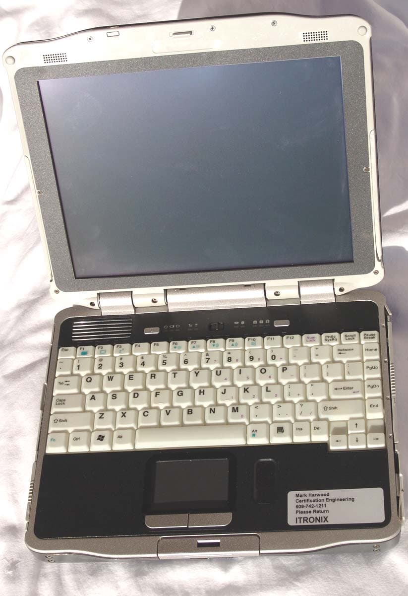
Click to zoom
Application Details
- Equipment Class
- PCB - PCS Licensed Transmitter
- Date of Grant
- Aug 14, 2006
- Application Purpose
- Original Equipment
- Date of Application
- Aug 14, 2006
- Equipment Note
- IX270-MC5720
- Frequency Range
- 824.70000000 - 848.31000000
- Country
- United States
Documents & Files
Document Text
Text extracted from the exhibit documents filed with the FCC. Open a document above to read the original.
Users Manual
Getting Started This online document, GoBook XR-1 Help , contains all the information you need to set up and use your GoBook XR-1. For information on printing, navigating or otherwise using GoBook XR-1 Help, see the How to Use This Help System topics. If you have suggestions for how we may improve this document, please see Documentation Feedback. Unpacking Your System Inside your packaging you will find: Standard Parts Standard Features O ptional Features GoBook ® XR-1 Help 72_0130_001 2006-07-10 © 2006 Itronix Corporation. All rights reserved. GoBook ® XR-1 Help Page 1 of 92GoBook XR-1 Help 8/3/2006file://C:\Documents and Settings\harwoodm\Local Settings\Temp\~hh2D1C.htm Optional Parts and Accessories Where to Look For Information About Your Computer About Windows Startup Problems? If your computer does not startup properly, try these solutions first: z Connect the AC adapter to charge the battery if it is not charged NOTE If the AC adapter is connected and functioning properly, the Power LED on the AC adapter should be lit as well as the External Power LED on the GoBook XR-1. z If the AC adapter is connected but the unit will still not turn on, make sure the electrical outlet you are using works z Check to make sure the battery is installed and charged properly z If the battery does not begin charging, perform the following: 1. Remove the battery. 2. Connect the AC adapter. 3. Turn on the computer by pressing the Power Button . 4. Reinstall the battery. The Battery LED is a steady green while the battery is charging. 72_0130_001 2006-07-10 © 2006 Itronix Corporation. All rights reserved. GoBook ® XR-1 Help 72_0130_001 2006-07-10 © 2006 Itronix Corporation. All rights reserved. GoBook ® XR-1 Help Page 2 of 92GoBook XR-1 Help 8/3/2006file://C:\Documents and Settings\harwoodm\Local Settings\Temp\~hh2D1C.htm Safety Read these instructions carefully. Following these guidelines will help prevent damage to your computer and help protect your personal safety. z Read and follow all warnings and instructions marked on the product and noted in this documentation, including the Notices and Compliance section z Follow all warnings and instructions noted in Windows Help and Support , found on the Start Menu z The first time you use your computer, we recommend that you carefully read the section on Power Management to familiarize yourself with basic battery information and ensure optimum performance z CAUTION To reduce the risk of fire, only use a No. 26 AWG or larger telecommunication line cord z CAUTION This notebook computer is designed to be used with the provided dedicated AC Adapter or Vehicle Adapter z Unplug the computer from the power outlet before cleaning. Use a damp cloth for cleaning. Aerosols, solvents, or strong detergents are not recommended cleaning solutions and may void your warranty. For system decontamination recommendations please contact your service technician z Slots and openings in the computer case are for ventilation purposes. Do not block or cover these openings or the system could overheat z Do not place the product on a soft surface such as a bed, sofa, or rug where the ventilation slots and openings may be blocked z Do not place this product near or over a radiator or heat register z Do not place this product in a built-in installation unless proper ventilation is provided z Do not operate the computer at temperatures above 140°F (60°C) or below -10°F (-23C) z Do not store the computer at temperatures above 167°F (75°C) or below -67°F (-55°C) z Do not step on or place anything on the power cord z Do not slam the display lid when you close it z Do not place any object on top of the computer when the display is closed z If you use the computer with an extension cord, ensure that the total ampere ratings of all the devices sharing the extension do not exceed the rating of the extension cord or the rating of the wall outlet Page 3 of 92GoBook XR-1 Help 8/3/2006file://C:\Documents and Settings\harwoodm\Local Settings\Temp\~hh2D1C.htm z Do not push foreign objects into the computer through any of the slots or openings. Dangerous voltages are present, which could cause electric shock, fire, or damage sensitive components z The computer is designed to withstand spills. If a spill occurs, power off the computer and wipe it down before continuing to use the computer z For best results, use a power strip with a built-in surge protector. Do not use inferior extension cords as this may result in damage to your computer z FAA regulations require that all transmit/receive devices be turned off during flight. If you have radios in your computer (including GPS) and your computer is equipped with a radio on/off switch, please use it to turn your radios off during flight. If you have radios and you do not have a switch to turn the radios off, either leave your computer off during flight or contact your help desk for assistance Service and Upgrade Safety and Precautions z Do not attempt to service this product yourself, as opening or removing covers may expose you to dangerous voltage points or other risks and may void your warranty. Refer all servicing to qualified service personnel z Unplug this product from the wall outlet and refer servicing to authorized service personnel under the following conditions: { When the power cord or plug is damaged or frayed { If the product does not operate normally when the operating instructions are followed. Adjust only those controls that are covered by the operating instructions since improper adjustment of other controls may result in damage and will often require extensive work by a qualified technician to restore the product to normal condition { If the product exhibits a distinct change in performance, indicating a need for service z Do not upgrade or service this computer without prior authorization from the manufacturer. Damage caused by servicing that is not authorized may void your warranty z Before performing any manufacturer authorized ser…
Text truncated - open the document above for the full version.
Cover Letter(s)
209 Dayton Street, Suite 205 Edmonds, WA 98020-3581 425 771-4482 425 486-1933 Fax August 7, 2006 Northwest EMC, Inc. 22975 NW Evergreen Parkway, #400 Hillsboro, OR 97124 % Vicki Albertson Re: Applicant: Itronix, Corporation FCC ID: KBCIX270-MC5720 1.) Limited Modular Certification for the Sierra Wireless, Inc., Model: MC5720 PCI Express Mini-Card Model: MC5720 CDMA 1x EV-DO, dual band. 2.) Co-location with the FCC ID: KBCIX270-WL3945 and KBCIX270-BT2022. TCB Committee, On behalf of Itronix Corporation we request a Limited Modular Certification for the embedded Sierra Wireless PCI Express Mini-Card, Model: MC5720 installed in the IX270 Rugged PC under rule Parts 22H & 24E. We also request that this Certification include Co-location with the above referenced Limited Modular Certified Intentional Radiators. Exhibits supporting this request are submitted with this application. We would like to reference the OEM, Sierra Wireless, Inc. Modular Certification test report prepared by CCS for all of the conducted test data. The radiated spurious and ERP/EIRP measurements made by NW EMC, Inc. would cover the integration of the MC5720 embedded module into the IX270 host with two new antenna combinations. The IX270 Vehicle Mount option extends many of the PC I/O ports and the switches the RF output of the WAN radio to an external antenna. Placing the IX270 in the cradle automatically causes the cradle contact board to switch the output of the MC8765 transmitter from the internal antenna located in the PC display, to and through the IX270 Vehicle Mount to an SMA connector and then to the external antenna. The external vehicular antenna sold by Itronix with this package is a 3 dBi gain antenna manufactured by MaxRad Model: BMLPVDB800/1900 along with the Model: LMR195 vehicle antenna ¾” magnetic mount with 17 ft of coax. Please let me know if you should require any further information. Best Regards, Rod Munro Agent, Itronix Corp. President, Spectrum Technology, Inc. [email protected]
Cover Letter(s)
Northwest EMC TCB Compliance Opinion Rev. 9/15/03 SPTE0020 Information about the Applicant Company Name Spectrum Technology Grantee Itronix Corporation Address 209 Dayton Street Suite #205 City, State, Zip Edmonds, WA 98020 Job Number SPTE0020 Model IX270-MC5720 FCC ID KBCIX270-MC5720 Agent Spectrum Technology, Inc. Approval Type Original Equipment Class TNB Licensed Non-Broadcast Base Station Transmitter Rule Part 22/24 Industry Canada Information Model Industry Canada ID Rule Part Overview We would like to reference the OEM, Sierra Wireless, Inc. Modular Certification test report prepared by CCS for all of the conducted test data. The radiated spurious and ERP/EIRP measurements made by NW EMC, Inc. would cover the integration of the MC5720 embedded module into the IX270 host with two new antenna combinations. The IX270 Vehicle Mount option extends many of the PC I/O ports and the switches the RF output of the WAN radio to an external antenna. Placing the IX270 in the cradle automatically causes the cradle contact board to switch the output of the MC8765 transmitter from the internal antenna located in the PC display, to and through the IX270 Vehicle Mount to an SMA connector and then to the external antenna. The external vehicular antenna sold by Itronix with this package is a 3 dBi gain antenna manufactured by MaxRad Model: BMLPVDB800/1900 along with the Model: LMR195 vehicle antenna ¾” magnetic mount with 17 ft of coax. Recommendation All items have been resolved and completed to my satisfaction; therefore I recommend this application for approval. Signature 8/12/2006 Dean Ghizzone, TCB Committee Northwest EMC TCB Compliance Opinion Rev. 9/15/03 SPTE0020 Findings Opinions Specification Requirements Description 47 Cfr 2.1033(C)(3) Installation guide, operating instructions,user manual Opinion The device meets the requirements of the rule. Discussion The client has provided the necessary exhibit. Reference User Manual.pdf Specification Requirements Description 47 Cfr 2.1033(C)(8) DC Voltages and Current Opinion The device meets the requirements of the rule. Discussion The client has provided the necessary exhibit. Reference Tune upand Alignment Procedure Specification Requirements Description 47 Cfr 2.1033(c)9) Tune-up procedure Opinion The device meets the requirements of the rule. Discussion The client has provided the necessary exhibit. Reference Tune upand Alignment Procedure Specification Requirements Description 47 Cfr 2.1033(C)(10) Schematic diagram Opinion The device meets the requirements of the rule. Discussion The client has provided the necessary exhibit. Reference Schematics.pdf Specification Requirements Description 47 Cfr 2.1033(c)(11) Internal and external photos Opinion The device meets the requirements of the rule. Discussion The client has provided the necessary exhibit. Reference Internal Photos.pdf, External Photos.pdf Specification Requirements Description 47 Cfr 2.1033(b)(6) Conversions showing how the test results were achieved Opinion The device meets the requirements of the rule. Discussion The client has provided the necessary exhibit. Reference Report-SPTE0020.pdf Northwest EMC TCB Compliance Opinion Rev. 9/15/03 SPTE0020 Specification Requirements Description Required Exhibit Test Setup Photo Exhibit Opinion The device meets the requirements of the rule. Discussion The client has provided the necessary exhibit. Reference Report-SPTE0020.pdf Specification Requirements Description 47 Cfr 2.1046 RF Power Output Opinion The device meets the requirements of the rule. Discussion The client has provided the necessary exhibit. Reference Test Report OEM Conducted Specification Requirements Description 47 Cfr 2.1049 Occupied Bandwidth Opinion The device meets the requirements of the rule. Discussion The client has provided the necessary exhibit. Reference Test Report OEM Conducted Specification Requirements Description 47 Cfr 2.1051 Spurious emissions at antenna terminals Opinion The device meets the requirements of the rule. Discussion The client has provided the necessary exhibit. Reference Test Report OEM Conducted Specification Requirements Description 47 Cfr 2.1053 Field Strength of spurious radiations Opinion The device meets the requirements of the rule. Discussion The client has provided the necessary exhibit. Reference Report-SPTE0020.pdf Specification Requirements Description 47 Cfr 2.1055 Frequency Stability Opinion The device meets the requirements of the rule. Discussion The client has provided the necessary exhibit. Reference Test Report OEM Conducted Specification Requirements Description 47 Cfr 2.1057 Frequency Spectrum to be investigated Opinion The device meets the requirements of the rule. Discussion The client has provided the necessary exhibit. Reference Report-SPTE0020.pdf Northwest EMC TCB Compliance Opinion Rev. 9/15/03 SPTE0020 Specification Requirements Description 47 Cfr 1.1310 RF Exposure Limits Opinion The device meets the requirements of the rule. Discussion The client has provided the necessary exhibit. Reference RF Exposure.pdf Specification Requirements Description 47 Cfr 22.355 Frequency Tolerance Opinion The device meets the requirements of the rule. Discussion The client has provided the necessary exhibit. Reference Test Report OEM Conducted Specification Requirements Description 47 Cfr 22.913(a) The ERP of mobile transmitters<= 7 Watts. Opinion The device meets the requirements of the rule. Discussion The client has provided the necessary exhibit. Reference Report-SPTE0020.pdf Specification Requirements Description 47 Cfr 22.917(e) Out of Band Emissions Opinion The device meets the requirements of the rule. Discussion The client has provided the necessary exhibit. Reference Report-SPTE0020.pdf Specification Requirements Description 47 Cfr 24.52 RF Exposure Limits Opinion The device meets the requirements of the rule. Discussion The client has provided the necessary exhibit. Reference RF Exposure.pdf Specification Requirements Desc…
Text truncated - open the document above for the full version.
External Photos
Applicant: Itronix, Corporation FCC ID: KBCIX270-MC5720 1 External Photos IX270 Top View Bottom View, FCC & IC ID Label Location Applicant: Itronix, Corporation FCC ID: KBCIX270-MC5720 2 IX270 Front View Open Applicant: Itronix, Corporation FCC ID: KBCIX270-MC5720 3 IX270 Right Side IX270 Left Side Applicant: Itronix, Corporation FCC ID: KBCIX270-MC5720 4 External Photos CRMA Express Module housing the MC5720 Embedded Module CRMA Express Module Top Side CRMA Express Module Bottom SIM Card Side
ID Label/Location Info
Applicant: Itronix Corp. FCC ID: KBCIX270-MC5720, Co-located with KBCIX270-BT2022 & KBCIX270-WL3945 FCC Identifier Label Location Identifier label is located on the bottom of the IX270 Facsimile FCC/IC Identifier labels applicable to the stand-alone model and the three co-located combinations are located on the four following pages: 1.) KBCIX270-MC5720 2.) KBCIX270-BT2022, KBCIX270-WL3945 & KBCIX270-MC5720 3.) KBCIX270-BT2022 & KBCIX270-MC5720 4.) KBCIX270-WL3945 & KBCIX270-MC5720
Internal Photos
Applicant: Itronix, Corporation FCC ID: KBCIX270-MC5720 1 Internal Photos IX270 Top view, PC closed, back display cover removed WAN, WLAN & GPS antennas visible IX270 WAN SkyCross antenna center above and enlargement below. GPS module and antenna to the left of the WAN SkyCross antenna above. WLAN Main and Aux antenna located upper right and left hand sides of display. Applicant: Itronix, Corporation FCC ID: KBCIX270-MC5720 2 CRMA Express WAN location Enlargement with the CRMA Express IX270-MC5720 installed. Applicant: Itronix, Corporation FCC ID: KBCIX270-MC5720 3 Internal Photos CRMA Express Module housing the MC5720 Embedded Module CRMA Express Module Top Side CRMA Express Module Bottom SIM Card Side Applicant: Itronix, Corporation FCC ID: KBCIX270-MC5720 4 CRMA Express Module With -MC5720 PCI Express Mini Card Internal Photos of the MC5720 Mini PCI Express Module are on the on the next two pages:
Operational Description
Applicant: Itronix Corporation FCC ID: KBCIX270-MC5720 Antenna Information Internal and External WAN Antenna Information FCC ID: KBCIX270-MC5720 Antenna Model Antenna Part No. Frequency (MHz) Antenna Type Antenna Gain (dBi) IX270 PRIMARY WAN ANTENNA 59-0521-001R 824 - 1880 Meander Line Antenna 1.5 @ 850 IX270 PRIMARY WAN ANTENNA 59-0521-001R 824 - 1880 Meander Line Antenna -1.5 @ 1900 External – MaxRad 3 dBi Gain BMLPVDB800/1900 806 - 960 Low profile vertical 3 External – MaxRad 3 dBi Gain BMLPVDB800/1900 1710-1990 Low profile vertical 3
RF Exposure Info
Applicant: Itronix, Corporation FCC ID: KBCIX270-MC5720 FCC ID: KBCIX270-WL3945 FCC ID: KBCIX270-BT2022 1 Co-Located Exposure Condition Compliance with 47 CFR 15.247(i) “Systems operating under the provisions of this section shall be operated in a manner that ensures that the public is not exposed to radio frequency energy levels in excess of the Commission's guidelines. See § 1.1307(b)(1) of this chapter.” The EUT will only be used with a separation distance of 20 centimeters or greater between the antenna and the body of the user or nearby persons and can therefore be considered a mobile transmitter per 47 CFR 2.1091 (b). Calculations are provided for each radio transmitting through its own internal antenna and optional external antenna. The total transmit power is less than 1.5 W (ERP), therefore the EUT is categorically excluded from routine environmental evaluation per 47 CFR 2.1091(c). The MPE estimates are as follows: Table 1 in 47 CFR 1.1310 defines the maximum permissible exposure (MPE) for the general population. The exposure level at a 20 cm distance from the EUT’s transmitting antenna is calculated using the general equation: S = (PG)/4πR 2 Where: S = power density (mW/cm 2 ) P = power input to the antenna (mW) G = numeric power gain relative to an isotropic radiator R = distance to the center of the radiation of the antenna (20 cm = limit for MPE estimates) PG = EIRP Solving for S, the maximum power densities 20 cm from the transmitting antennas are summarized in the tables on the following pages: Applicant: Itronix, Corporation FCC ID: KBCIX270-MC5720 FCC ID: KBCIX270-WL3945 FCC ID: KBCIX270-BT2022 2 MPE Estimates for Self Located Device FCC ID: KBCIX270-MC5720 CDMA Antenna Type Antenna Part No. Transmit Frequency Max Peak Conducted Output Power Antenna Gain Minimum Antenna Cable Loss Power Density @ 20 cm General Population Exposure Limit from 1.1310 Ratio of Power Density to the Exposure Limit IX270 (MHz) (mW) (dBi) (dB) (mW/cm 2 ) (mW/cm 2 ) PRIMARY WAN ANTENNA 59-0521-001R 1875.0 922.57 -1.5 0.89 0.1057 1 0.106 PRIMARY WAN ANTENNA 59-0521-001R 836.0 963.83 1.5 1.50 0.1915 0.55 0.349 External MaxRad BMLPVDB800/1900 1875.0 922.57 3 2.77 0.1978 1 0.198 External MaxRad BMLPVDB800/1900 836.0 963.83 3 3.33 0.1775 0.55 0.309 Worst Case Ratio of Power Density to the Exposure Limit = 0.349 Excerpts from TCB Training, April 3, 2002, “Mobile Transmitters”, Slide 6: “Devices operating in multiple frequency bands When RF exposure evaluation is required for TCB approval o Separate antennas – estimated minimum separation distances may be considered for the frequency bands that do not require evaluation or TCB approval, however, the estimated distance should take into account the effect of co-located transmitters. (Note 24) Note 24 According to multiple frequency exposure criteria, the ratio of field strength or power density to the applicable exposure limit at the exposure location should be determined for each transmitter and the sum of these ratios must not exceed 1.0 for the location to be compliant .” The sum of the ratio(s) (power density to the exposure limit) does not exceed 1.0; therefore, the exposure condition is compliant with FCC rules. Applicant: Itronix, Corporation FCC ID: KBCIX270-MC5720 FCC ID: KBCIX270-WL3945 FCC ID: KBCIX270-BT2022 3 MPE Estimates for Self Located Device FCC ID: KBCIX270-WL3945 WLAN, IEEE 802.11 (a) (b) & (g) Antenna Type Antenna Part No. Transmit Frequency Max Peak Conducted Output Power Antenna Gain Minimum Antenna Cable Loss Power Density @ 20 cm General Population Exposure Limit from 1.1310 Ratio of Power Density to the Exposure Limit (GHz) (mW) (dBi) (dB) (mW/cm 2 ) (mW/cm 2 ) PiFa MAIN TWR12WIPI02A 5 100 -2.56 6.5 0.002 1 0.002 PiFa MAIN TWR12WIPI02A 2.4 318 -2.72 3.5 0.015 1 0.015 External MaxRad MAXC24503 2.4 318 3 4.6 0.044 1 0.044 External MaxRad BMAXC24505 2.4 318 5 4.6 0.069 1 0.069 Worst Case Ratio of Power Density to the Exposure Limit = 0.069 MPE Estimates for Self Co-located Device FCC ID: KBCIX270-BT2022 Bluetooth Radio Antenna Type Antenna Part No. Transmit Frequency Max Peak Conducted Output Power Antenna Gain Minimum Antenna Cable Loss Power Density @ 20 cm General Population Exposure Limit from 1.1310 Ratio of Power Density to the Exposure Limit (MHz) (mW) (dBi) (dB) (mW/cm 2 ) (mW/cm 2 ) Well Green Technology Co. Ltd. IX270-B/T or R12Y-B/T TWR12BLPI01A 2441 36.22 -2.56 0.69 0.0032 1 0.0032 Worst Case Ratio of Power Density to the Exposure Limit = 0.0032 Applicant: Itronix, Corporation FCC ID: KBCIX270-MC5720 FCC ID: KBCIX270-WL3945 FCC ID: KBCIX270-BT2022 4 Worst Case Co-located Exposure Condition FCC ID: KBCIX270-MC5720 FCC ID: KBCIX270-WL3945 FCC ID: KBCIX270-BT2022 Per Note 24 shown below, the Sum of Worst Case Power Ratios cannot exceed 1.0 CDMA Radio Worst Case Ratio of Power Density to the Exposure Limit 802.11abg Radio Worst Case Ratio of Power Density to the Exposure Limit Bluetooth Radio Worst Case Ratio of Power Density to the Exposure Limit Sum of Worst Case Ratios (Power Density to the Exposure Limit) FCC Limit for Sum of Worst Case Ratios 0.349 0.069 0.0032 0.421 1.0 PASS The results shown in the above table are equivalent to the Sum of the EIRP of the Two Co-located Transmitters (EIRP TX1 + EIRP TX2) compared to the exposure limit. The benefit of this method, is that accounts for transmitters operating at different frequencies against different exposure limits.
RF Exposure Info
Applicant: Itronix, Corporation FCC ID: KBCIX270-MC5720 1 Compliance with 47 CFR 15.247(i) “Systems operating under the provisions of this section shall be operated in a manner that ensures that the public is not exposed to radio frequency energy levels in excess of the Commission's guidelines. See § 1.1307(b)(1) of this chapter.” The EUT will only be used with a separation distance of 20 centimeters or greater between the antenna and the body of the user or nearby persons and can therefore be considered a mobile transmitter per 47 CFR 2.1091 (b). Calculations are provided for each radio transmitting through its own internal antenna and optional external antenna. The total transmit power is less than 1.5 W (ERP), therefore the EUT is categorically excluded from routine environmental evaluation per 47 CFR 2.1091(c). The MPE estimates are as follows: Table 1 in 47 CFR 1.1310 defines the maximum permissible exposure (MPE) for the general population. The exposure level at a 20 cm distance from the EUT’s transmitting antenna is calculated using the general equation: S = (PG)/4πR 2 Where: S = power density (mW/cm 2 ) P = power input to the antenna (mW) G = numeric power gain relative to an isotropic radiator R = distance to the center of the radiation of the antenna (20 cm = limit for MPE estimates) PG = EIRP Solving for S, the maximum power densities 20 cm from the transmitting antennas are summarized in the tables on the following pages: Applicant: Itronix, Corporation FCC ID: KBCIX270-MC5720 2 MPE Estimates for Self Located Device FCC ID: KBCIX270-MC5720 CDMA Antenna Type Antenna Part No. Transmit Frequency Max Peak Conducted Output Power Antenna Gain Minimum Antenna Cable Loss Power Density @ 20 cm General Population Exposure Limit from 1.1310 Ratio of Power Density to the Exposure Limit IX270 (MHz) (mW) (dBi) (dB) (mW/cm 2 ) (mW/cm 2 ) PRIMARY WAN ANTENNA 59-0521-001R 1875.0 922.57 -1.5 0.89 0.1057 1 0.106 PRIMARY WAN ANTENNA 59-0521-001R 836.0 963.83 1.5 1.50 0.1915 0.55 0.349 External MaxRad BMLPVDB800/1900 1875.0 922.57 3 2.77 0.1978 1 0.198 External MaxRad BMLPVDB800/1900 836.0 963.83 3 3.33 0.1775 0.55 0.309 Worst Case Ratio of Power Density to the Exposure Limit = 0.349 Excerpts from TCB Training, April 3, 2002, “Mobile Transmitters”, Slide 6: “Devices operating in multiple frequency bands When RF exposure evaluation is required for TCB approval o Separate antennas – estimated minimum separation distances may be considered for the frequency bands that do not require evaluation or TCB approval, however, the estimated distance should take into account the effect of co-located transmitters. (Note 24) Note 24 According to multiple frequency exposure criteria, the ratio of field strength or power density to the applicable exposure limit at the exposure location should be determined for each transmitter and the sum of these ratios must not exceed 1.0 for the location to be compliant .” The sum of the ratio(s) (power density to the exposure limit) does not exceed 1.0; therefore, the exposure condition is compliant with FCC rules.
Test Report
Spectrum Technology IX270-MC5720 July 10, 2006 Report No. SPTE0020.1 Report Prepared By www.nwemc.com 1-888-EMI-CERT © 2006 Northwest EMC, Inc 22975 NW Evergreen Parkway Suite 400 Hillsboro, Oregon 97124 Certificate of Test Issue Date: July 10, 2006 Spectrum Technology Model: IX270-MC5720 Emissions Test Description Specification Test Method Pass Fail AC Powerline Conducted Emissions of the Receiver FCC 15.107:2006 ANSI C63.4:2003 Effective Radiated Power FCC 22H:2006 ANSI/TIA/EIA-603-B:2002 Effective Radiated Power FCC 24E:2006 ANSI/TIA/EIA-603-B:2002 Spurious Radiated Emissions of the Receiver FCC 15.109:2006 ANSI C63.4:2003 Out of Band Emissions FCC 22H:2006 ANSI/TIA/EIA-603-B:2002 Out of Band Emissions FCC 24E:2006 ANSI/TIA/EIA-603-B:2002 Modifications made to the product See the Modifications section of this report Test Facility The measurement facility used to collect the data is located at: Northwest EMC, Inc. 22975 NW Evergreen Parkway, Suite 400; Hillsboro, OR 97124 Phone: (503) 844-4066 Fax: 844-3826 This site has been fully described in a report filed with and accepted by the FCC (Federal Communications Commission) and Industry Canada. Approved By: Greg Kiemel, Director of Engineering This report must not be used to claim product certification, approval, or endorsement by NVLAP, NIST, or any agency of the federal government of the United States of America. Product compliance is the responsibility of the client, therefore the tests and equipment modes of operation represented in this report were agreed upon by the client, prior to testing. This Report may only be duplicated in its entirety. The results of this test pertain only to the sample(s) tested, the specific description is noted in each of the individual sections of the test report supporting this certificate of test. Northwest EMC Revision History Revision 05/05/03 Revision Number Description Date Page Number 00 None Northwest EMC Accreditations and Authorizations Revision 03/18/05 FCC: Accredited by NVLAP for performance of FCC radio, digital, and ISM device testing. Our Open Area Test Sites, certification chambers, and conducted measurement facilities have been fully described in reports filed with the FCC and accepted by the FCC in letters maintained in our files. Northwest EMC has been accredited by ANSI to ISO / IEC Guide 65 as a product certifier. We have been designated by the FCC as a Telecommunications Certification Body (TCB). This allows Northwest EMC to certify transmitters to FCC specifications in accordance with 47 CFR 2.960 and 2.962. NVLAP: Northwest EMC, Inc. is accredited under the United States Department of Commerce, National Institute of Standards and Technology, and National Voluntary Laboratory Accreditation Program for satisfactory compliance with the requirements of ISO/IEC 17025 for Testing Laboratories. The NVLAP accreditation encompasses Electromagnetic Compatibility Testing in accordance with the European Union EMC Directive 89/336/EEC, ANSI C63.4, MIL- STD 461E, DO-160D and SAE J1113. Additionally, Northwest EMC is accredited by NVLAP to perform radio testing in accordance with the European Union R&TTE Directive 1999/5/EEC, the requirements of FCC, and the RSS radio standards for Industry Canada. NVLAP LAB CODE 200629-0 NVLAP LAB CODE 200630-0 NVLAP LAB CODE 200676-0 Industry Canada: Accredited by NVLAP for performance of Industry Canada RSS and ICES testing. Our Open Area Test Sites and certification chambers comply with RSS 212, Issue 1 (Provisional) and have been filed with Industry Canada and accepted. Northwest EMC has been accredited by ANSI to ISO / IEC Guide 65 as a product certifier. We have been designated by NIST and recognized by Industry Canada as a Certification Body (CB) per the APEC Mutual Recognition Arrangement (MRA). This allows Northwest EMC to certify transmitters to Industry Canada technical requirements. CAB: Designated by NIST and validated by the European Commission as a Conformity Assessment Body (CAB) to conduct tests and approve products to the EMC directive and transmitters to the R&TTE directive, as described in the U.S. - EU Mutual Recognition Agreement. TÜV Product Service: Included in TUV Product Service Group's Listing of Recognized Laboratories. It qualifies in connection with the TUV Certification after Recognition of Agent's Testing Program for the product categories and/or standards shown in TUV's current Listing of CARAT Laboratories, available from TUV. A certificate was issued to represent that this laboratory continues to meet TUV's CARAT Program requirements. Certificate No. USA0401C. TÜV Rheinland: Authorized to carryout EMC tests by order and under supervision of TÜV Rheinland. This authorization is based on "Conditions for EMC-Subcontractors" of November 1992. Northwest EMC Accreditations and Authorizations Revision 03/18/05 NEMKO: Assessed and accredited by NEMKO (Norwegian testing and certification body) for European emissions and immunity testing. As a result of NEMKO's laboratory assessment, t…
Text truncated - open the document above for the full version.
Contact Information
Applicant
Ray Garcia(Agency Manager)
Test Firm
Northwest EMC, Inc.Greg Kiemel
Technical Specifications
| # | Rule Parts | Frequency Range | Power Output | Emission | Tolerance |
|---|---|---|---|---|---|
| 2 | 22H | 824.7 MHz - 848.31 MHz | 383.00 mW | 1M39F9W | 2.5 ppm |
Other Applications from General Dynamics Itronix Corporation

KBCIX-BR-51
Jan 20, 2008IX-BTBR51
Equipment Class
DSS - Part 15 Spread Spectrum Transmitter
KBCIX-MC8775
May 30, 2007IX-MC8775
Equipment Class
PCB - PCS Licensed Transmitter
KBCIX-4965AGN
May 21, 2007IX-4965AGN
Equipment Class
NII - Unlicensed National Information Infrastructure TX
KBCIX-AC595
Apr 19, 2007IX-AC595 DUAL-BAND CDMA/EV-DO PCMCIA MODEM CARD
Equipment Class
PCB - PCS Licensed Transmitter
KBCIX-NW620
Mar 13, 2007IX-NW620 CDMA/EV-DO
Equipment Class
PCB - PCS Licensed Transmitter