KBCIX300AC775WLGoBook Tablet PC with PCS and WLAN
General Dynamics Itronix Corporation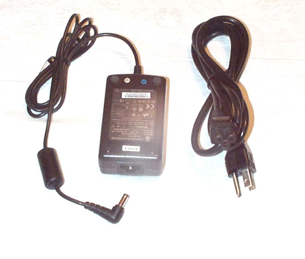
Click to zoom
Application Details
- Equipment Class
- PCB - PCS Licensed Transmitter
- Date of Grant
- Feb 06, 2005
- Application Purpose
- Original Equipment
- Date of Application
- Feb 06, 2005
- Equipment Note
- GoBook Tablet PC with PCS and WLAN
- Frequency Range
- 824.20000000 - 848.80000000
- Country
- United States
Documents & Files
Document Text
Text extracted from the exhibit documents filed with the FCC. Open a document above to read the original.
Users Manual
termsRev1 Identification GoBook Tablet PC (IX300) Help Copyright Notice © Copy right 2003 Itronix Corporation. All rights reserved. No part of this document may be reproduced, transmitted, transcribed, stored in a retrieval sy stem, or translated into any other language or computer language in whole or in part, in any form or by any means, whether it be electronic, mechanical, magnetic, optical, manual, or otherwise, without the prior written consent of Itronix Corporation, South 801 Stevens Street, Spokane, Washington 99204. Disclaimer This document is printed in the U.S.A. Itronix Corporation reserves the right to revise the manual and make periodic changes to the content without a direct or inferred obligation to Itronix to notify any person of such revision or changes. Itronix Corporation does not assume responsibility for the use of this help manual, nor for any patent infringements or other rights or third parties who may use the manual. This document contains valuable trade secrets and proprietary information of Itronix Corporation. This product is available for purchase under the terms of the Itronix Hardware Purchase and Software License Agreement. Itronix hardware products may be reconditioned, or be manufactured from parts and components that may be new, used, rebuilt, or recycled and in some cases, the hardware product may not be new and may have been previously installed. In any event, Itronix warranty terms apply. Trademark Notice Itronix is a registered trademark of Itronix Corporation. GoBook is a registered trademark of Itronix Corporation Microsoft, MS, Windows, and MS-DOS are registered trademarks of Microsoft Corporation. IBM is a trademark of International Business Machines Corporation. Compliance Statements The GoBook Tablet PC (IX300) computer has been tested and found to comply with the limits for a Class B digital device, pursuant to Part 15 of the FCC Rules. These limits are designed to provide reasonable protection against harmful interference in a residential installation. This equipment generates, uses, and can radiate radio frequency energy and, if not installed and used in accordance with the instructions, may cause harmful interference to radio communications. However, there is no guarantee that interference will not occur in a particular installation. GoBook™ Tablet PC Help Legal Information Page 1 termsRev1 If this equipment does cause harmful interference to radio or television reception, which can be determined by turning the equipment off and on, the user is encouraged to try to correct the interference by one or more of the following measures: Reorient or relocate the receiving antenna. Increase the separation between the equipment and receiver. Connect the equipment into an outlet on a circuit different from that to which the receiver is connected. Consult the dealer or an experienced radio/TV technician for help. The GoBook Tablet PC (IX300) computer complies with Part 68 of the FCC Rules. On the bottom of this equipment is a label that contains, among other information, the FCC registration number and ringer equivalence number (REN) for this equipment. If requested, this information must be provided to the telephone company. The REN is used to determine the quantity of devices which may be connected to the telephone line. Excessive RENs on the telephone line may result in the devices not ringing in response to an incoming call. In most, but not all areas, the sum of the RENs should not exceed five (5.0). To be certain of the number of devices that may be connected to the line, as determined by the total RENs, contact the telephone company to determine the maximum REN for the calling area. The GoBook Tablet PC (IX300) computer may be connected to the telephone network using the RJ-11 jack provided. If this equipment causes harm to the telephone network, the telephone company will notify you in advance that temporary discontinuance of service may be required. If advance notice isn’t practical, the telephone company will notify the customer as soon as possible. Also, you will be advised of your right to file a complaint with the FCC if you believe it is necessary. The telephone company may make changes in its facilities, equipment, operations, or procedures that could affect the operation of the equipment. If this happens, the telephone company will provide advance notice in order for you to make the necessary modifications in order to maintain uninterrupted service. If trouble is experienced with this equipment, please contact the equipment manufacturer for repair and/or warranty information. Do not attempt repairs of this equipment yourself without obtaining manufacturer authorized parts and documentation. If the trouble is causing harm to the telephone network, the telephone company may request you remove the equipment from the network until the problem is resolved. Compliance Statement for Canada NOTICE The Industry Canada label identifies certified equipment. This certification means that the equipment meets certain telecommunications network protective, operational and safety requirements as prescribed in the appropriate Terminal Equipment Technical Requirements document(s). The Department does not guarantee the equipment will operate to the user’s satisfaction. Before installing this equipment, users should ensure that it is permissible to be connected to the facilities of the local telecommunications company. The equipment must also be installed using an acceptable method of connection. The customer should be aware that compliance with the above conditions may not prevent degradation of service in some situations. Repairs to certified equipment should be made by a representative designated by the supplier. Any repairs or alterations made by the user to this equipment, or equipment malfunctions, may give the telecommunications company cause to request the user to disconnect the equipment. Users should ensure for their own protection that the e…
Text truncated - open the document above for the full version.
Cover Letter(s)
EXHIBIT XIII - Cover Letters New Certification Report for the FCC ID: KBCIX300AC775WL Cover Letter 1.) Certification Action Requested Cover Letter 2.) Request for Confidentiality under Part 0.459. Cover Letter 3.) ITRONIX Agent Authorization letter allowing Rod Munro to Sign FCC Form 731 on behalf of ITRONIX, Corp. Exhibit 13
Cover Letter(s)
209 Dayton Street, Suite 205 Edmonds, WA 98020-3581 425 771-4482 425 486-1933 Fax __________________________________________________________________________________________ January 25, 2005 Federal Communications Commission Authorization and Evaluation Division C/O AmericanTCB, Inc. 6731 Whitter Avenue McLean, VA 22101 Re: Attestation of compliance for mobile configuration, (20 cm min. antenna to user) FCC ID: KBCIX300AC775WL Applicant: ITRONIX, Corporation. Models: IX300 with AirCard 775, (WAN), under Parts 22H, & 24E, and WM168b-Molex, (WLAN) Intentional Radiator under Part 15.247. Gentlemen: Spectrum Technology, Incorporated has tested the above referenced rugged Tablet PC with the co-located transmitters. Measurements were made in accordance with the applicable requirements contained in the Parts 2, 15.247, 22H and 24E of Title 47, CFR. To the best of my knowledge, these tests were performed using the criteria established in ANSI, TIA-603-B and ANSI C63.3 as applicable. In this configuration of the IX300 the WAN and WLAN do NOT transmit at the same time. The radio modules are physically and electrically identical to the originally certified modules as defined by Part 2.908. The results of the measurements referenced below demonstrate the equipment complies with the Part 15 and Part 22H and 24E limits, with the referenced RF devices installed and simultaneously transmitting in pairs. 1.) Test Report # 1 – Supplemental EMC measurements were made for a previously Certified transmitter, a Sierra Wireless, Inc., FCC ID: N7NAC775, Model: AirCard 775, operating under Part 24E. Measurements were made to check the radiated spurious emissions, and measure the transmitter EIRP under Parts 22H and 24E when the approved modular device is located in the IX300 Tablet PC. The original Sierra Wireless test report is referenced for all relevant conducted test data. 2.) Test Report # 2 - Supplemental EMC measurements were made of a previously Certified Intentional Radiator, a AirVast Technology, Inc., FCC ID: QDWWM168B, Model WM168b-Molex, to demonstrate continued compliance with the limits established under Part 15.247 applicable to DTS when installed co- located in the IX300 Tablet PC. The original conducted test report data prepared by CSC for Twinhead International Corp. is referenced in this application. The digital device emissions were measured and verified to meet the Part 15.107(a), 15.207(a) conducted emissions limits from .150 to 30 MHz and 15.109, (a) radiated emissions limits from 30 to 1000 MHz applicable to Class B digital devices. The applicable rule sections are listed in the three test reports uploaded under Exhibit 6.
External Photos
Applicant: ITRONIX, Corporation FCC ID: KBCIX300AC775WL Front View IX300 Back View IX300 Exhibit 3 External Photos Applicant: ITRONIX, Corporation FCC ID: KBCIX300AC775WL ‘Top View IX300 AC775 Antenna visible Right Side View IX300 Exhibit 3 External Photos Applicant: ITRONIX, Corporation FCC ID: KBCIX300AC775WL Left Side View IX300 Bottom View IX300 Exhibit 3 External Photos Applicant: ITRONIX, Corporation FCC ID: KBCIX300AC775WL AC Power adapter with ferrite core Model: LSE9802A2060 Exhibit 3 External Photos
ID Label/Location Info
Applicant: ITRONIX, Corp. FCC ID: KBCIX300AC775WL EXHIBIT 1. LIST OF EXHIBITS and FCC IDENTIFICATION LABEL LIST OF EXHIBITS DESCRIPTION EXHIBITS REFERENCE I. Identification label Information 1 2.1033 (b) 7 & 2.925 & General Information 1A 1. Production Plans 2.1031 2. Application References N/A 3. Data submittal Procedure 4. Similar Certified Transmitter II. Certification Data 2 III. External Photographs 3 2.1033 (b) 7 IV. Block Diagrams (Circuit Diagrams) confidential 4 2.1033 (b) 5 V. Schematic Diagrams confidential 5 2.1033 (b) 5 VI Test Report 1 6 2.1033 (b) 6 Part 22H & 24E – Supplemental IX300 EMC Test Report with previously Certified Transmitter, a Sierra Wireless, Inc., FCC ID: N7NAC775, Model: AirCard 775. 1) RF Power Output (2.1046) 2) Transmitter Radiated Spurious Emissions (2.1053) 3) Equivalent Isotropic Radiated Power Note: Files from the OEM’s Certification uploaded for the other test report data and exhibits for items required by Parts 22 & 24. VI Test Report 2 6 2.1033 (b) 6 Part 15.247 – DTS, Supplemental IX300 EMC Test Report with previously Certified, WLAN, Intentional Radiator, a AirVast Technology, Inc., FCC ID: QDWWM168B, Model: WM168b-Molex. 1) Conducted Output Power Section 15.247(b)1 2) EIRP limit Section 15.247(b) 3 3) Spurious Emissions Section 15.247 (c) Note: Files from the OEM’s Certification uploaded for the other test report data and exhibits for items required by Part 15.247. VII. Test Set-up Procedures 7 2.1041 VIII. Instruction Manual 8 2.1033 (b) 3 Exhibit 1 Applicant: ITRONIX, Corp. FCC ID: KBCIX300AC775WL IX. Internal Photographs 9 2.1033 (b) 7 X. Part List and Tune Up Procedures confidential 10 2.1033 XI. MPE RF Exposure Information 11 2.1093,15.247(b)4 XII. Operational Description confidential 12 2.1033(b)1,2,4,8 Antenna Requirements 12 15.203 XIII. Cover Letter, Certification Action Requested 13 Cover Letter, Request For Confidentiality 13 Cover Letter, Authorization to sign FCC Form 731 13 EXHIBIT 1. FCC IDENTIFICATION LABEL & LOCATION FCC ID label location is on the bottom right side of the Tablet PC. The name ITRONIX is on the SILVER label heading. ⇓ The FCC Identification label required under section: 47 CFR 2.1033(c) 11, is located on following page for the FCC ID: KBCIX300AC775WL. The Part 15.19 Users statement page follows that page. Exhibit 1
Internal Photos
Applicant: ITRONIX, Corp. FCC ID: KBCIX300AC775WL Part 1 INTERNAL PHOTOGRAPHS OF THE IX300 NOTE: This FCC ID / configuration does not contain a WLAN. The submitted photos of the IX300 under Part 2 INTERNAL PHOTOGRAPHS are from a previous filing under FCC ID: FKGTABLETPC, the WLAN Intentional Radiator is physically and electrically identical to the current IX300 configuration except, for the addition of the AirCard 775 which utilizes the PCMCIA slot. The ONLY other change is on page 6 and a corrected copy of page 6 is on the following page. The Bluetooth and WLAN antennas were simply switched one for the other indicated on the following page. EXHIBIT 9 Internal Photos IX300
Internal Photos
Compliance Certification Services Inc. Report No: B30813209 Page 4 INTERNAL PHOTOGRPHS OF EUT Internal of EUT --- 1 Internal of EUT --- 2 Compliance Certification Services Inc. Report No: B30813209 Page 5 Internal of EUT --- 3 Internal of EUT --- 4 Compliance Certification Services Inc. Report No: B30813209 Page 6 Internal of EUT --- 5 Internal of EUT --- 6 WLAN Antenna Position Bluetooth Antenna Position Compliance Certification Services Inc. Report No: B30813209 Page 7 Internal of EUT --- 7 Internal of EUT --- 8 Compliance Certification Services Inc. Report No: B30813209 Page 8 Internal of EUT --- 9 Internal of EUT --- 10 Compliance Certification Services Inc. Report No: B30813209 Page 9 Internal of EUT --- 11 Internal of EUT --- 12 Compliance Certification Services Inc. Report No: B30813209 Page 10 Internal of EUT --- 13 Internal of EUT --- 14 Compliance Certification Services Inc. Report No: B30813209 Page 11 Internal of EUT --- 15 Internal of EUT --- 16 Compliance Certification Services Inc. Report No: B30813209 Page 12 Internal of EUT --- 17 Internal of EUT --- 18 Compliance Certification Services Inc. Report No: B30813209 Page 13 Internal of EUT --- 19 Internal of EUT --- 20 Compliance Certification Services Inc. Report No: B30813209 Page 14 Internal of EUT --- 21
RF Exposure Info
Applicant: ITRONIX, Corp. FCC ID: KBCIX300AC775WL EXHIBIT 11 - MPE CALCULATION DATA Model: IX300 with two co-located transmitters listed below. 1.) AirCard775, (WAN) GSM850 S (mw/cm^2) at 20cm = 0.14529791 Tx Freq: 836.6 MHz Antenna Gain: -2.8 dBi Max Peak Conducted Power @ antenna terminal input: 31.44 dBm Channel # Frequency (MHz) Peak Power (Watts) GSMK Mode Peak Power (dBm) GSMK Mode (Ch.128) 824.2 1.39 31.43 (Ch.190) 836.6 1.39 31.44 (Ch.251) 848.8 1.37 31.38 2.) AirCard775, (WAN) PCS1900 S (mw/cm^2) at 20cm = 0.218403386 Tx Freq: 1850.20 MHz Antenna Gain: 2.0 dBi Max Peak Conducted Power @ antenna terminal input: 28.41 dBm Channel # Frequency (MHz) Peak Power (Watts) GSMK Mode Peak Power (dBm) GSMK Mode (Ch.512) 1850.2 0.684 28.35 (Ch.661) 1880.0 0.693 28.41 (Ch.810) 1909.8 0.687 28.37 3.) WM168b-Molex, (WLAN) S (mw/cm^2) at 20cm = 0.0039 Tx Freq: 2412 MHz Antenna Gain: -3.04 dBi Max Peak Conducted Power @ antenna terminal input: 16.03 dBm Frequency GHz Power dBm Cable loss Corrected Level dBm Ant. Gain dBi EIRP 2.412 15.45 .58 16.03 -3.04 12.99 2.437 15.30 .58 15.88 -3.04 12.84 2.462 14.97 .58 15.55 -3.04 12.51 Exhibit 11 1 Applicant: ITRONIX, Corp. FCC ID: KBCIX300AC775WL No Multiple Frequency Exposure The AC775 WAN and WLAN cannot transmit at the same time therefore there is no Multiple Frequency Exposure. General Population/Uncontrolled Prediction of MPE Limit OET Bulletin 65, Edition 97-01 ________ S = PG/4 πR 2 R = √ PG/4πS S= power density P= power input to the antenna G= power gain of the antenna in the direction of interest relative to an isotropic radiator R= distance to the center of radiation of the antenna 1.) AirCard775, (WAN) GSM850 Tx Frequency: 836.60 MHz Max. Peak Power Antenna Input Terminal: 31.44 dBm Antenna gain: -2.80 dBi S= 0.56 (mW/cm^2) P= 1393.1568 (mW) G= 0.52 (numeric) R = 10.21 (cm) S (mw/cm^2) at 20cm = 0.14529791 2.) AirCard775, (WAN) PCS1900 Tx Frequency: 188000 MHz Max. Peak Power Antenna Input Terminal: 28.41 dBm Antenna gain: 2.00 dBi S= 1.00 (mW/cm^2) P= 693.4258 (mW) G= 1.58 (numeric) R = 9.35 (cm) S (mw/cm^2) at 20cm = 0.218403386 3.) WM168b-Molex, (WLAN) Tx Frequency: 2412.00 MHz Max. Peak Power Antenna Input Terminal: 16.03 dBm Antenna gain: -3.04 dBi S= 1.00 mW/cm^2) P= 40.0867 (mW) G= 0.50 (numeric) R = 1.26 (cm) S (mw/cm^2) at 20cm = 0.003956028 Exhibit 11 2
Test Report
2004 Sierra Wireless, Inc. This document contains information which is proprietary and confidential to Sierra Wireless, Inc. Disclosure to persons other than the officers, employees, agents, or subcontractors of the Company or licensee of this document without the prior written permission of Sierra Wireless, Inc. is strictly prohibited. FCC Parts 22 and 24 Test Report For 850/900/1800/1900 MHz GSM/EDGE PC CARD WIRELESS MODEM Model: AIRCARD 775 FCC ID: N7NAC775 Prepared by SIERRA WIRELESS INC. 13811 WIRELESS WAY RICHMOND, BC V6V 3A4 CANADA Test Date(s): May 20, 2004 SIERRA WIRELESS, INC. FCC Part 22 & 24 Test Report AC775 May 20, 2004 Page 2 of 60 2004 Sierra Wireless, Inc. The contents of this page are subject to the confidentiality information on page one. Table of Contents 1 Introduction and Purpose ......................................................................... 3 2 Test Summary .......................................................................................... 3 3 Description of Equipment Under Test ..................................................... 4 4 RF Power Output ..................................................................................... 5 4.1 Test Procedure .................................................................................................... 5 4.2 Test Equipment.................................................................................................... 5 4.3 Test Results ......................................................................................................... 6 5 Occupied Bandwidth................................................................................ 7 5.1 Test Procedure .................................................................................................... 7 5.2 Test Results ......................................................................................................... 7 5.3 Test Plots............................................................................................................. 8 6 Out of Band Emissions at Antenna Terminals ...................................... 20 6.1 Test Procedure .................................................................................................. 20 6.2 Test Equipment.................................................................................................. 20 6.3 Test Results ....................................................................................................... 21 6.4 Test Plots........................................................................................................... 22 7 Block Edge Compliance ........................................................................ 49 7.1 Test Procedure .................................................................................................. 49 7.2 Test Equipment.................................................................................................. 49 7.3 Test Results ....................................................................................................... 50 7.4 Test Plots........................................................................................................... 51 8 Frequency Stability Versus Temperature .............................................. 55 8.1 Summary of Results........................................................................................... 55 8.2 Test Procedure .................................................................................................. 55 8.3 Test Equipment.................................................................................................. 55 8.4 Test Results ....................................................................................................... 56 9 Frequency Stability Versus Voltage ...................................................... 58 9.1 Summary of Results........................................................................................... 58 9.2 Test Procedure .................................................................................................. 58 9.3 Test Equipment.................................................................................................. 58 9.4 Test Results ....................................................................................................... 59 SIERRA WIRELESS, INC. FCC Part 22 & 24 Test Report AC775 May 20, 2004 Page 3 of 60 2004 Sierra Wireless, Inc. The contents of this page are subject to the confidentiality information on page one. 1 Introduction and Purpose This document provides the FCC test data for the AC755 wireless modem. The tests included in this report are limited to all conducted tests required. The radiated tests were performed at an external test facility. 2 Test Summary FCC RULE DESCRIPTION OF TEST RESULT PAGE 2.1046 RF Power Output Complies 5 2.1049 Occupied Bandwidth Complies 7 2.1051, 22.901(d) 22.917, 24.238(a) Out of Band Emissions at Antenna Terminals Complies 20 FCC part 22H/24E Block Edge Requirements Complies 49 2.1053 Field Strength of Spurious Radiation Complies See CCS Report 2.1055 Frequency Stability versus Temperature Complies 55 2.1055 Frequency Stability versus Voltage Complies 58 The tests described in this report were performed by Mr. Darryl Simpson at: Sierra Wireless, Inc. 13811 Wireless Way Richmond, B.C. V6V 3A4 Canada SIERRA WIRELESS, INC. FCC Part 22 & 24 Test Report AC775 May 20, 2004 Page 4 of 60 2004 Sierra Wireless, Inc. The contents of this page are subject to the confidentiality information on page one. 3 Description of Equipment Under Test The Sierra Wireless Inc. model AirCard 775 is a quad-band PCMCIA card wireless modem operating on the GSM/GPRS/EDGE network. In the US and Canada, only cellular and PCS bands are used for GSM/GPRS operation, so this test report only contains data for these two bands (850MHz and 1900MHz). The EUT was tested in both modes of operation: GMSK modulation and 8-PSK mod…
Text truncated - open the document above for the full version.
Test Report
EXHIBIT VI. Test Report 1 Supplemental Test Report For New Certification Of Previously Certified AirCard 775 Under FCC ID: KBCIX300AC775WLBT IX300 GoBook Tablet PC With AirCard 775, WLAN and Bluetooth Certification Requested Under Parts 22H & 24E Prepared On Behalf Of ITRONIX, Corporation 801 South Stevens Street Spokane, WA 99204 Prepared By Spectrum Technology, Inc. 209 Dayton Street, Suite 205 Edmonds, WA 98020 425 771-4482 December 17, 2004 Applicant: ITRONIX, Corporation. FCC ID: KBCIX300AC775WLBT Exhibit VI 2 Supplemental Test Report TABLE OF CONTENTS Cover Page 1 Table of Contents 2 RF Conducted Power Output GSM850 and PCS1900 (2.1046) 3 GSM850 Part-22H Effective Radiated Power (TIA-603-B) 4 Field Strength of Spurious Radiated Emissions (2.1053) 5 - 6 Spurious Emissions Attenuation Measured by Signal Substitution Method 7 (TIA-603-B) PCS1900 Part-24E Effective Isotropic Radiated Power (TIA-603-B) 8 Field Strength of Spurious Radiated Emissions (2.1053) 9 – 10 Spurious Emissions Attenuation Measured by Signal Substitution Method 11 (TIA-603-B) Note: Please refer to the original Certification Test Report data prepared by Sierra Wireless, Inc., for all conducted test data applicable to their Model: AirCard 775, FCC ID: N7NAC775, in support of this instant application. Applicant: ITRONIX, Corporation. FCC ID: KBCIX300AC775WLBT Exhibit VI 3 Exhibit 6 Test - RF Conducted Power Output FCC ID: KBCIX300AC775WLBT Grantee: ITRONIX, Corp. Model: IX300 with AirCard 775, (WAN), WM168b-Molex, (WLAN), & MUBTC2-TH, (Bluetooth) Authorization Procedure: Part 2.1046 Limit: Part 24.232(b) Test Date: 12/09/04 Please Note: The applicant wishes to reference all the conducted test data contained in the Sierra Wireless, Inc., FCC Parts 22 and 24 Test Report for the Model: AirCard 775, FCC ID: N7NAC775. A full copy of this report was submitted along with this test report. The maximum conducted output power from page 6 of this referenced report is listed in the following table: Frequency MHz Channel GMSK Mode 8-PSK Mode 836.6 190 31.44 dBm 26.89 dBm 1880.0 661 28.41 dBm 25.94 dBm Method of Measurement Prior to starting the radiated measurements the RF output port of the AirCard 775 was directly coupled to the input of the Agilent spectrum analyzer through a special RF adapter short cable and SMA connector. The instrument was set to measure peak power output and the measured results for low, mid and high channels within the GSM850 and PCS band are reported below with cable loss included. This measurement was done to confirm proper output of the transmitter over the two bands in which it was tested. Conducted Measurement Data Frequency (MHz) Channel # Peak Power (Watts) Peak Power GMSK (dBm) 824.2 (Ch.128) 1.361 31.34 836.6 (Ch.190) 1.361 31.34 848.8 (Ch.251) 1.372 31.37 1850.2 (Ch.512) 0.696 28.44 1880.0 (Ch.661) 0.7132 28.53 1909.8 (Ch.810) 0.7208 28.59 Applicant: ITRONIX, Corporation. FCC ID: KBCIX300AC775WLBT Exhibit VI 4 Exhibit 6 Test: Effective Radiated Power (ERP) Output Grantee: ITRONIX, Corp. FCC ID: KBCIX300AC775WLBT Model: IX300 with AirCard 775, (WAN), WM168b-Molex, (WLAN), & MUBTC2-TH, (Bluetooth) Effective Radiated Power Output measurements by Substitution Method according to ANSI/TIA-603-B, approved November 7, 2002. The measurements were made as prescribed in TIA-603-B 2.2.17.2.2, a – f. The EUT was set up at the OATS facility on the non-conductive turntable 3 meters from the receive antenna. The height and turntable rotation was adjusted for the maximum reading on the spectrum analyzer for each antenna polarization. Only the polarization with the highest levels observed is reported below. The EUT was removed and a half wave dipole antenna, adjusted for each frequency, was substituted in its place with the height of this antenna consistent with the position of the EUT antenna. The RF signal generator with a known output fed a signal to the dipole antenna to obtain and record the path loss in dB as LOSS. LOSS = Generator Output Power (dBm) – Analyzer reading (dBm). The ERP was determined by the formula referenced below. ERP (dBm) = LVL (dBm) + LOSS (dB) Freq. MHz ERP (W) ERP (dBm) Ref. Level (dBm) Path LOSS Ant. Pol. H / V 824.20 0.935 29.71 -4.85 34.56 V 836.60 1.219 30.86 -4.31 35.17 V 848.80 1.455 31.63 -3.78 35.41 V Part 22.913(a) ERP of mobile and auxiliary test transmitters not to exceed 7 Watts Measurement distance of 3 meters EUT to receive antenna. Location: Spectrum Technology Inc., Fluke Park II OATS facility Date: Dec. 09, 2004 EUT tuned to maximum power. Test made with a fully charged standard battery with IX300 in the Desk Mount. Note: The antenna used is a standard Sierra Wireless AirCard 775 model that is ½ wave in the cellular band and full wave in the PCS band. Itronix Part Number Air Card Mnf PN Mnf SKU Frequency Band Length (+/- 0.25 mm) 47-0215-001 AC 775 12003096000170 AMP/PCS/GSM/DC S 45.5 mm Applicant: ITRONIX, Corporation. FCC ID: KBCIX300AC775WLBT Exhibit VI 5 Exhibit 6 Test - Field Strength of Spurious Radiated Emissions FCC ID: KBCIX300AC775WLBT Grantee: ITRONIX, Corp. Model: IX300 with AirCard 775, (WAN), WM168b- Molex, (WLAN), & MUBTC2-TH, (Bluetooth) Minimum Standard Specified: Part 22.917 (e) = 43+10log (PO) dB Test Results: Equipment complies with standard Authorization Procedure: Part 2.1053 Test Equipment Set Up: See photos and block diagram in Exhibit 7 Frequency Range Observed: .30 to 9.000 GHz Test Frequencies: 824.2, 836.6 and 848.8 MHz Power Output Conducted: 31.44 dBm or, 1.393 Watts Power Output Radiated 31.63 dBm ERP or 1.455 Watts ERP Spurious Limit = 43 + 10Log (PO) = 44.44 dB below the carrier Test date: 12/09/04 Location: OATS Fluke Park II Everett, WA Discussion The field strength of the radiated spurious emissions and harmonics was measured at 3 meters EUT to antenna distance using 1 MHz RBW and VBW. The transmitter output of the AirCard 775 was terminated into a 50 ohm coaxial termination. A high pass filter was used prior to the input to the pr…
Text truncated - open the document above for the full version.
Test Report
CLASS B VERIFICATION MEASUREMENTS Under Title 47 CFR, Parts 15.107(a), 15.207(a) Conducted Emissions and Parts 15.109(a), & & 15.209(a) Radiated Emissions For ITRONIX, Corporation IX300 Tablet PC December 17, 2004 Prepared By Spectrum Technology, Inc. 209 Dayton Street Edmonds, WA 98020 425 771-4482 2 VERIFICATION TABLE OF CONTENTS Cover Page 1 Table of Contents 2 Letter of Submittal and Compliance 3 TEST RESULTS AND DATA AC Conducted Emissions Part 15.107(a), 15.207(a) 4 - 7 Field Strength of Radiated Emissions Part 15.109 (a), 15.209(a) 8 - 10 Open Field Site and Antenna/Equipment Orientation 11 4 TEST: CONDUCTED SPURIOUS EMISSIONS Manufacturer: ITRONIX, Corporation. Name: IX300 Tablet PC Model: IX300 with AirCard 775, (WAN), WM168b-Molex, (WLAN), & MUBTC2-TH, (Bluetooth) Setup: The equipment under test (EUT) was set up in accordance with the provisions of ANSI C63.4- 2001, Section 7, on a 1 X 1.5-meter non-conductive test table at our Edmonds, Washington facility. The tabletop is 80 cm above a 2.5 x 2-meter horizontal ground plane and 40 cm forward from a 2.25 X 2.4-meter vertical ground plane. The two ground planes are continuously grounded along the common seam. The two 50 ohm/ 50 uHy Line Impedance Stabilization Networks (LISN) are grounded to the horizontal ground plane. The EUT was placed in a typical operational arrangement following the 10-cm spacing as detailed in Section 6.2 and 11.2, and the power cord of the EUT plugged into the first LISN. The signal output of this LISN was fed to the Agilent E7405 EMC analyzer using a 9 kHz bandwidth, which served as the measuring instrument. The peripheral equipment, if any were powered from a separate LISN. Discussion: Measurements of the AC power line conducted spurious emissions were made with the ITRONIX IX300 inserted into the Desk Stand and set up in …
Text truncated - open the document above for the full version.
Contact Information
Applicant
Ray Garcia(Agency Manager)
Technical Contact
Spectrum Technology, Inc.Rod Munro
[email protected]425 771-4482
209 Dayton Street, Suite 205 · Edmonds, Washington · United States
Technical Specifications
| # | Rule Parts | Frequency Range | Power Output | Emission | Tolerance |
|---|---|---|---|---|---|
| 4 | 22H | 824.2 MHz - 848.8 MHz | 489.00 mW | 240KG7W | 2.5 ppm |
Other Applications from General Dynamics Itronix Corporation

KBCIX-BR-51
Jan 20, 2008IX-BTBR51
Equipment Class
DSS - Part 15 Spread Spectrum Transmitter
KBCIX-MC8775
May 30, 2007IX-MC8775
Equipment Class
PCB - PCS Licensed Transmitter
KBCIX-4965AGN
May 21, 2007IX-4965AGN
Equipment Class
NII - Unlicensed National Information Infrastructure TX
KBCIX-AC595
Apr 19, 2007IX-AC595 DUAL-BAND CDMA/EV-DO PCMCIA MODEM CARD
Equipment Class
PCB - PCS Licensed Transmitter
KBCIX-NW620
Mar 13, 2007IX-NW620 CDMA/EV-DO
Equipment Class
PCB - PCS Licensed Transmitter