KBCIX550RIM802IX550 Rugged Laptop PC with RIM 802 DataTAC Radio
General Dynamics Itronix Corporation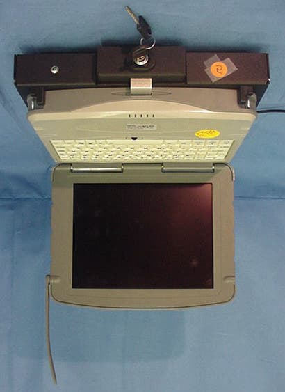
Click to zoom
Application Details
- Equipment Class
- TNB - Licensed Non-Broadcast Station Transmitter
- Date of Grant
- Jul 19, 2001
- Application Purpose
- Original Equipment
- Date of Application
- Jun 25, 2001
- Equipment Note
- IX550 Rugged Laptop PC with RIM 802 DataTAC Radio
- Frequency Range
- 806.00000000 - 821.00000000
- Country
- United States
Documents & Files
Document Text
Text extracted from the exhibit documents filed with the FCC. Open a document above to read the original.
Users Manual
GoBook Pro HelpPage 1 of 74 file://C:\WINDOWS\TEMP\~hh6357.htm5/23/01 Getting Started Congratulations on your purchase of the Itronix GoBook Pro computer! Your new GoBook Pro features the most innovative advances in portable computing technology. It combines state-of-the-art ergonomics with a rugged, durable architecture to provide you with a notebook computer that is compact, powerful, rugged and easy to use. Designed for a wide range of business and personal productivity applications, the GoBook Pro is an ideal choice for use in applications that require the ultimate in ruggedness, durability, performance and intrinsic safety. For maximum expandability without compromising portability, the GoBook Pro accommodates a number of modules, including USB interfaces and one PC card slot. The high capacity hard disk drive provides you with plenty of storage space for multimedia files and applications. The GoBook Pro features a standard 81-key Nitevue® keyboard (82-key international). The high- resolution 10.4-inch touch screen LCD panel provides clear and crisp viewing with touch screen convenience. This User’s Guide contains all the information you need to set up and use your new GoBook Pro. It describes all the features of the GoBook Pro in an easy-to-read yet thorough manner. GoBook Pro Help 1. Getting Started Topics GoBook Pro HelpPage 2 of 74 file://C:\WINDOWS\TEMP\~hh6357.htm5/23/01 Unpacking Your System Inside your packaging you will find: lItronix GoBook Pro computer lPower cord lAC adapter lBattery l2 Styluses lGoBook Pro Quick Start Guide You may have additional components or peripherals if you ordered these items separately. Check your packing slip for a complete list of items included in your package. 79_0100_001 © 2001 Itronix Corporation. All rights reserved. Precautions You can use your computer under a wide range of environmental conditions. However, to ensure long use and continued high performance, consider the following factors when setting up your computer: lFollow all warnings and instructions noted in this documentation and in the Windows Help program. lThe first time you use your computer, we recommend that you carefully read Power Management to familiarize yourself with some battery basics to ensure optimum battery performance lUnplug the computer from the power outlet before cleaning. Use a damp cloth for cleaning. Do GoBook Pro Help 1. Getting Started Topics GoBook Pro HelpPage 3 of 74 file://C:\WINDOWS\TEMP\~hh6357.htm5/23/01 not use aerosols, solvents, or strong detergents lSlots and openings in the computer case are for ventilation purposes. Do not block or cover these openings or the system could overheat lOn the bottom of the GoBook Pro, there is a label with information on the power requirements of this system. These requirements must be followed. If you are unsure of your local power supply, consult your dealer or local Power Company lDo not step on or place anything on the power cord lIf you use the computer with an extension cord, ensure that the total ampere ratings of all the devices sharing the extension do not exceed the rating of the extension cord or the rating of the wall outlet lNever push foreign objects into the computer through any of the slots or openings. Dangerous voltages are present, which could cause electric shock or fire, or damage sensitive components lFor best results, use a power strip with a built-in surge protector. Do not use inferior extension cords as this may result in damage to your computer 79_0100_001 © 2001 Itronix Corporation. All rights reserved. Checklists After opening the package, carefully inspect the contents. Contact your dealer if any items are missing or appear damaged. The shipping carton should contain the following: STANDARD lA GoBook Pro computer lA battery lAn AC adapter with power cord GoBook Pro Help 1. Getting Started Topics GoBook Pro HelpPage 4 of 74 file://C:\WINDOWS\TEMP\~hh6357.htm5/23/01 l2 Styluses lQuick Start Guide OPTIONS The following items are normally optional, but some vendors may include them in the standard package. Some items may not be available in some countries, or some vendors may choose not to carry all the items. lAdditional battery pack lShoulder Strap lAudio adapter cable CAUTION When purchasing any of the accessories listed above, purchase only those accessories that are approved for use with your computer. The above accessories are proprietary items. Your system vendor can obtain these approved accessories. If you use items that are not approved for use with this computer, you may cause your computer to malfunction, or to emit or receive electromagnetic radiation in excess of local regulations. For non-proprietary accessories such as PC Cards or printers, ensure that the accessory functions properly in your computer before making the purchase. Your system vendor may be able to recommend reliable brands and models. Features High Capacity Hard Disk Drive The computer has a high capacity hard disk drive, enabling you to install your favorite programs and store large multimedia files. Full Array of Ports and Connectors Your computer includes standard ports for connecting to peripherals such as USB devices and monitors. USB ports allow you to add many other peripherals. Bright SVGA LCD Your computer has a bright, easy to view SVGA LCD panel with integrated touch screen. Built-in Speaker and Microphone The speaker and internal microphone enable you to run a variety of multimedia applications. An optional audio adapter cable is available for connecting external speakers (headphones) and microphone. Function Keys GoBook Pro HelpPage 5 of 74 file://C:\WINDOWS\TEMP\~hh6357.htm5/23/01 Function keys allow you to suspend your computer, shut the LCDs off, and give you easy control of audio and your monitor. Where to Look For Information About Your Computer This User’s Manual describes the key elements of your computer. New users can find a simple step-by- step orientation in this chapter. About Win…
Text truncated - open the document above for the full version.
Users Manual
GoBook Pro HelpPage 36 of 74 file://C:\WINDOWS\TEMP\~hh6357.htm5/23/01 WARNING Incorrect settings can cause your system to malfunction. To correct mistakes, return to Setup and restore the Setup Defaults by pressing F9. I/O Device Configuration Menu The CPU communicates with external devices such as printers through devices called Input/Output (I/O) ports such as serial ports. These I/O devices require the use of system resources such as I/O addresses and interrupt lines. If these devices are Plug and Play, either the BIOS can allocate the devices during POST, or the operating system can do it. If the I/O devices are not Plug and Play, they may need to be set manually in Setup. On some systems, the chipset manages the communication devices. Other systems have, instead, a separate I/O chip on the motherboard for configuring and managing these devices. Many systems allow you to control the configuration settings for the I/O ports. Use this menu to specify how the I/O (Input and Output) ports are configured: lManually by you. FieldSetting Function Installed O/S:Other Win95 Win98 WinMe WinNT2K Select the operating system you use most often Reset Configuration Data: Yes No Yes erases all configuration data in a section of memory for ESCD (Extended System Configuration Data) which stores the configuration settings for non-PnP plug-in devices. Select yes when required to restore the manufacturer's defaults I/O Device Configuration sub-menuConfigure I/O Devices USB Host Controller Disabled Enabled Enables or Disables the USB hardware USB BIOS Legacy Support Disabled Enabled Enables or Disables support for USB Keyboards and Mice. GoBook Pro HelpPage 37 of 74 file://C:\WINDOWS\TEMP\~hh6357.htm5/23/01 lAutomatically by the BIOS during POST lAutomatically by a PnP Operating System such as Windows 95 after the Operating System boots. 79_0100_001 © 2001 Itronix Corporation. All rights reserved. The Security Menu FieldSetting Function Serial port A: Disabled Enabled Auto Disabled turns off the port . Enabled requires you to enter the base Input/Output address and the Interrupt number on the next line Auto makes the BIOS configure the port automatically during POST. GoBook Pro Help 6. Customizing Your BIOS Topics GoBook Pro HelpPage 38 of 74 file://C:\WINDOWS\TEMP\~hh6357.htm5/23/01 Enabling Supervisor Password requires a password for entering Setup. The passwords are not case sensitive. Pressing Enter at either Set Supervisor Password or Set User Password displays a dialog box like this: FieldSetting Function Set User Password Up to seven alphanumeric characters Pressing Enter displays the dialog box for entering the user password. In related systems, this password gives restricted access to SETUP menus. Set Supervisor Password Up to seven alphanumeric characters Pressing Enter displays dialog box for entering the supervisor password. In related systems, this password gives full access to Setup menus. Password on boot Enabled Disabled Enabled requires a password on boot. Requires prior setting of the Supervisor password. If supervisor password is set and this option disabled, BIOS assumes user is booting. Diskette access Enabled Disabled Enabled requires a password to boot from or access the floppy disk. fixed disk boot sector Normal Write Protect Write protects the boot sector on the hard disk for virus protection. Requires a password to format or Fdisk the hard disk. System backup reminder Virus check reminder Disabled Daily Weekly Monthly Displays a message during boot up asking (Y/N) if you have backed up the system or scanned it for viruses. Message returns on each boot until you respond with "Y". Daily displays the message on the first boot of the day, weekly on the first boot after Sunday, and monthly on the first boot of the month. GoBook Pro HelpPage 39 of 74 file://C:\WINDOWS\TEMP\~hh6357.htm5/23/01 NOTE In some systems, the User and supervisor passwords are related; you cannot have a User password without first creating a Supervisor password. In other systems, you can create and use them independently 79_0100_001 © 2001 Itronix Corporation. All rights reserved. The Power Menu The options available in power management depend upon the hardware installed in your system. Those shown here are from a typical system. GoBook Pro Help 6. Customizing Your BIOS Topics GoBook Pro HelpPage 40 of 74 file://C:\WINDOWS\TEMP\~hh6357.htm5/23/01 FieldSetting Function Power Savings Disabled Customized Maximum Power Savings Maximum Performance Maximum options: pre-defined values. Select Customize to make your own selections from the following fields. Disabled turns off all power management. Idle Mode On Off Turn of/off the Idle Mode power savings. Standby Timeout Off 1 min 2 min 4 min 6 min 8 min 12 min 16 min Inactivity period required to put system in Standby (partial power shutdown). Auto Suspend Timeout Off 5 min 10 min 15 min 20 min 30 min 40 min 60 min Inactivity period required after Standby to Suspend (maximum power shutdown). Suspend Mode Suspend Save to Disk Low power state to enter when the suspend timeout has occurred Hard Disk Timeout Disabled 10 sec 15 sec 30 sec 45 sec 1 min 2 min 4 min 6 min 8 min 10 min 15 min Inactivity period of hard disk required before standby (motor off). Video Timeout Disabled 10 sec 15 sec 30 sec 45 sec 1 min 2 min 4 min Set inactivity period required before independently turning off monitor. Disabled turns CRT off in Standby. GoBook Pro HelpPage 41 of 74 file://C:\WINDOWS\TEMP\~hh6357.htm5/23/01 79_0100_001 © 2001 Itronix Corporation. All rights reserved. The Boot Menu When you turn on your computer, it attempts to load the operating system (such as Windows 98) from the device of your choice. If it cannot find the operating system on that device it attempts to load it from one or more other devices according to the order specified in the Boot Menu. Boot devices can include hard drives, floppy drives, CD-ROMs, removable devices and network cards. NOTE Specifying any devic…
Text truncated - open the document above for the full version.
Attestation Statements
801 S. STEVENS STREET SPOKANE, WA 99204 509.624.3600 800.441.1309 FAX 509.828.4203 www.itronix.com June 25, 2001 Federal Communications Commission Equipment Authorization Branch 7435 Oakland Mills Road Columbia, MD 21046 In re: ITRONIX CORPORATION FCC ID: KBCIX550RIM802 Gentlemen: ltronix product identified as IX550 incorporates a RIM 802 radio. This radio operates on a 25% duty cycle. The SAR investigation conducted by Celltech Testing and Engineering Services located in Kelowna BC utilized the 25% duty cycle during this investigation. We hereby confirm that the factory-set duty cycle of all production units shall not exceed 25%. Sincerely, SIGNATURE Fred Phillips Certification Engineer ITiRONIX
Cover Letter(s)
Celltech Research Inc. 1955 Moss Court, Kelowna, B.C. Canada V1Y 9L3 Tel. 250-860-3130 •• Fax. 250-860-3110 •• [email protected] www.celltechlabs.com June 25, 2001 Federal Communications Commission Equipment Approval Services 7435 Oakland Mills Road Columbia, MD 21046 SUBJECT: ITRONIX CORPORATION FCC ID: KBCIX550RIM802 Part 90 Certification Gentlemen: On behalf of Itronix Corporation we hereby submit an application for Part 90 Certification of the Itronix IX550 Rugged Laptop PC with RIM 802 DataTAC Radio Modem as follows: FCC ID: KBCIX550RIM802 Model(s): IX550 Equipment Class: Licensed Non-Broadcast Station Transmitter (TNB) Equipment Type: Rugged Laptop PC with RIM 802 DataTAC Radio Modem Tx Freq. Range: 806 - 821 MHz Rx Freq. Range: 851 - 870 MHz Max. RF Output Power: 1.13 Watts (ERP) Emission Designator: 20K0F1D Attached is the authorization letter, confidentiality request, Part 90 measurement report data and test plots, SAR measurement report data & photographs, MPE measurement report data & photographs, test setup photographs, EUT photographs, FCC ID label & location, block diagrams (confidential), circuit diagrams (confidential), circuit description (confidential), parts list (confidential), tune-up procedure (confidential), operational description (confidential), and the user's manual with RF exposure warning statements. Please note that this application replaces the Class II Permissive Change application submitted under EA100800. If you have any questions or comments concerning the above, please contact the undersigned. Sincerely, Shawn McMillen General Manager Celltech Research Inc. Testing & Engineering Lab cc: Itronix Corporation
Cover Letter(s)
Celltech Research Inc. 1955 Moss Court, Kelowna, B.C. Canada V1Y 9L3 Tel. 250-860-3130 •• Fax. 250-860-3110 •• [email protected] www.celltechlabs.com July 16, 2001 Federal Communications Commission Equipment Approval Services 7435 Oakland Mills Road Columbia, MD 21046 Attn: Frank Coperich SUBJECT: Itronix Corporation FCC ID: KBCIX550RIM802 731 Confirmation No.: EA101486 Correspondence Reference No.: 19940 Dear Frank: On behalf of Itronix Corporation is our response to your e-mail dated July 13, 2001 requesting additional information for the subject application. 1. Attached is the revised Confidentiality Request letter, which includes the Antenna Specifications. 2. The ERP calculation of the EUT was performed as follows: The forward power into the substitution half-wave dipole was determined by taking into account the cable loss between the signal generator and the antenna, and further correcting for the gain of the substitution antenna relative to an ideal half-wave dipole antenna with 0dBd gain. Attached are the calibrated gain values for the substitution half-wave dipole antenna. 3. Attached are the antenna gain values for the substitution double-ridged wave-guide antenna used in determining the radiated spurious emissions of the EUT. We trust this information is sufficient to issue the grant. If you have any further questions or comments, please do not hesitate to contact me. Sincerely, Shawn McMillen General Manager Celltech Research Inc. Testing & Engineering Lab cc: Itronix Corporation
External Photos
CELLTECH RESEARCH INC. Test Report S/N: 062501-129KBC 1955 Moss Court, Kelowna Dates of Tests: April 03-06, 2001 B.C. Canada V1Y 9L3 FCC Part 90 Certification © 2001 Celltech Research Inc. ITRONIX CORP. FCC ID: KBCIX550RIM802 Rugged Laptop PC with RIM 802 DataTAC Radio Modem EXTERNAL EUT PHOTOGRAPHS CELLTECH RESEARCH INC. Test Report S/N: 062501-129KBC 1955 Moss Court, Kelowna Dates of Tests: April 03-06, 2001 B.C. Canada V1Y 9L3 FCC Part 90 Certification © 2001 Celltech Research Inc. ITRONIX CORP. FCC ID: KBCIX550RIM802 Rugged Laptop PC with RIM 802 DataTAC Radio Modem EXTERNAL EUT PHOTOGRAPHS CELLTECH RESEARCH INC. Test Report S/N: 062501-129KBC 1955 Moss Court, Kelowna Dates of Tests: April 03-06, 2001 B.C. Canada V1Y 9L3 FCC Part 90 Certification © 2001 Celltech Research Inc. ITRONIX CORP. FCC ID: KBCIX550RIM802 Rugged Laptop PC with RIM 802 DataTAC Radio Modem EXTERNAL EUT PHOTOGRAPHS CELLTECH RESEARCH INC. Test Report S/N: 062501-129KBC 1955 Moss Court, Kelowna Dates of Tests: April 03-06, 2001 B.C. Canada V1Y 9L3 FCC Part 90 Certification © 2001 Celltech Research Inc. ITRONIX CORP. FCC ID: KBCIX550RIM802 Rugged Laptop PC with RIM 802 DataTAC Radio Modem EUT WITH CRADLE PHOTOGRAPHS CELLTECH RESEARCH INC. Test Report S/N: 062501-129KBC 1955 Moss Court, Kelowna Dates of Tests: April 03-06, 2001 B.C. Canada V1Y 9L3 FCC Part 90 Certification © 2001 Celltech Research Inc. ITRONIX CORP. FCC ID: KBCIX550RIM802 Rugged Laptop PC with RIM 802 DataTAC Radio Modem EUT WITH CRADLE PHOTOGRAPHS CELLTECH RESEARCH INC. Test Report S/N: 062501-129KBC 1955 Moss Court, Kelowna Dates of Tests: April 03-06, 2001 B.C. Canada V1Y 9L3 FCC Part 90 Certification © 2001 Celltech Research Inc. ITRONIX CORP. FCC ID: KBCIX550RIM802 Rugged Laptop PC with RIM 802 DataTAC Radio Modem VEHICLE ANTENNA PHOTOGRAPHS MaxRad Z562Unity Gain Antenna P/N: 46-0059-001 CELLTECH RESEARCH INC. Test Report S/N: 062501-129KBC 1955 Moss Court, Kelowna Dates of Tests: April 03-06, 2001 B.C. Canada V1Y 9L3 FCC Part 90 Certification © 2001 Celltech Research Inc. ITRONIX CORP. FCC ID: KBCIX550RIM802 Rugged Laptop PC with RIM 802 DataTAC Radio Modem VEHICLE ANTENNA PHOTOGRAPHS MaxRad Z568 Unity Gain Antenna P/N: 46-0064-001
ID Label/Location Info
CELLTECH RESEARCH INC. Test Report S/N: 062501-129KBC 1955 Moss Court, Kelowna Dates of Tests: April 03-06, 2001 B.C. Canada V1Y 9L3 FCC Part 90 Certification © 2001 Celltech Research Inc. ITRONIX CORP. FCC ID: KBCIX550RIM802 Rugged Laptop PC with RIM 802 DataTAC Radio Modem FCC ID LABEL & LOCATION LABELLING REQUIREMENTS PER §§ 2.925 The label shown shall be permanently affixed at a conspicuous location on the device and be readily visible to the user at the time of purchase.
Internal Photos
2 A 1.8 inch coax is routed from the radio to a MMCX to MMCX bulkhead in the magnesium case. Outside the magnesium case and under the keyboard bezel a 3.8 inch cable routes to the cradle contact board that uses the same mechanical switch as the IX250. From the cable a 17.5 inch cable routes up through the display hinge. The coax then routes up the back of the display case to the antenna matching network PCB. The matching PCB varies with network type and is generally not the same between IX550 and IX250 due to the different mechanical form factors. The back case is covered with a plastic overmold. Note that the antenna is located on the upper left corner on the display on the IX550 and on the upper right for the IX250. 3 In the IX250 the radio board is located on the same side as the IX550 but more towards the front of the unit. The IX250 does not use a bulkhead connector, but instead has a 8 inch coax that routes from the radio to a cradle contact board. The coax used is the same type as is used for IX550. The IX250 uses a different cradle contact board with additional functions, but the RF path is similar to IX550’s. The RF signal is routed onto the PCB through a mechanical switch and out towards the display. The second coax is approximately 20 inches in length. 4 The coax passes through a hole in the magnesium case and then routs through a hinge to the display case. It then routes up the right side in a channel to the antenna matching pcb. The side channel has a plastic cover to protect the coax and seal the display area. The antenna is located on the upper right corner. The IX250 and IX550 use the same metal radiating element encased in a slightly different overmold form. However, the overmold material is the same in both cases. Although significantly different in size, the RF functionality is the same. The RF path routes through an identical mechanical switch which allows the signal to be switched to an external antenna. Both boards were designed with 50 ohm characteristic impedance traces. Also on the RF signal path is a low capacitance transient voltage suppression (TVS) component which is intended to provide ESD protection to the radio. Both boards use the same TVS part. CELLTECH RESEARCH INC. Test Report S/N: 062501-129KBC 1955 Moss Court, Kelowna Dates of Tests: April 03-06, 2001 B.C. Canada V1Y 9L3 FCC Part 90 Certification © 2001 Celltech Research Inc. ITRONIX CORP. FCC ID: KBCIX550RIM802 Rugged Laptop PC with RIM 802 DataTAC Radio Modem INTERNAL EUT PHOTOGRAPHS CELLTECH RESEARCH INC. Test Report S/N: 062501-129KBC 1955 Moss Court, Kelowna Dates of Tests: April 03-06, 2001 B.C. Canada V1Y 9L3 FCC Part 90 Certification © 2001 Celltech Research Inc. ITRONIX CORP. FCC ID: KBCIX550RIM802 Rugged Laptop PC with RIM 802 DataTAC Radio Modem INTERNAL EUT PHOTOGRAPHS RIM 802 DataTAC Radio Modem
RF Exposure Info
GoBook Pro HelpPage 25 of 74 file://C:\WINDOWS\TEMP\~hh6357.htm5/23/01 RIM 902M radio, an application that uses one of these protocols must be installed on the computer and configured to communicate on COM4. Cisco Wireless LAN lGo to your preferred LAN application and run normally CAUTION While the RIM 802 radio is operating, the antenna must be at least 2.0 cm from all persons in order to comply with the FCC RF exposure limit. Radio (wireless modem) operators must make sure their radio unit is in compliance with these FCC regulations. See Optional Equipment and Accessories for important information about vehicle-mounted antennas. 79_0100_001 © 2001 Itronix Corporation. All rights reserved. Power Management Using the Battery Monitoring Battery Power There are two ways to monitor how much power the battery has left. 1.Click Start, Settings, Control Panel, Power Management (Power Options); then click the Power Meter tab. 2.Moving the cursor to the battery icon on the taskbar , without selecting anything, is the simplest way to check on battery power status. The status will show as a pop-up when you mouse-over the icon. NOTE If you do not see the battery icon on the taskbar, enable it in Start, Settings, Control Panel, Power Management. Choose the Advanced tab and select “Always show icon on the taskbar.” Low Battery Alarms GoBook Pro Help 5. Power Mangement Topics
RF Exposure Info
GoBook Pro HelpPage 46 of 74 file://C:\WINDOWS\TEMP\~hh6357.htm5/23/01 Communicating with Other Devices Connect the external device to either of the USB ports on the back of the cradle, and then place the GoBook Pro onto the vehicle cradle. You can install or remove the computer from the vehicle cradle without connecting or disconnecting the cables. External Antennas An external RF antenna also can be connected to the cradle using the TNC RF connector on the back of the vehicle cradle. FCC regulations require that users of vehicle-mounted antennas must use only antennas authorized for use with the GoBook Pro in order to meet FCC RF exposure limits. Please contact your organizations’s help desk for a list of approved vehicle-mounted antennas. For mounting installation and/or mounting instructions for these types of antennas, see the instructions that accompany each antenna. RF Antenna Placement WARNING Improper installation and/or operating configurations of permanent and magnetic vehicle- mounted antennas may cause FCC RF exposure limits to be exceeded. Vehicle-mounted antennas must be placed at least 20 cm from operators and bystanders. Placement of a vehicle-mounted antenna 1.Measure and identify an area 20 cm (8 inches) in from the edges of the vehicle roof (see diagram below). 2.Place the antenna within that area. To maximize RF performance, position the antenna in the center of the vehicle roof. charging process is trying to put a little more capacity into the battery. External power can be removed at this time since the battery is virtually full. lIf your battery is new or has not been used for several weeks, rely on the indicator light to determine when the battery is fully charged. The gas gauge is unreliable in these cases; it may read 100 percent, but the actual capacity is only 10 percent.
RF Exposure Info
CELLTECH RESEARCH INC. Test Report S/N: 062501-129KBC 1955 Moss Court, Kelowna Date(s) of Tests: June 13, 2001 B.C. Canada V1Y 9L3 FCC SAR Measurements _______________________________________________________________________________________________________ © 2001 Celltech Research Inc. CERTIFICATE OF COMPLIANCE SAR EVALUATION This wireless mobile and/or portable device has been shown to be compliant for localized Specific Absorption Rate (SAR) for uncontrolled environment/general exposure limits specified in ANSI/IEEE Std. C95.1-1992 and has been tested in accordance with the measurement procedures specified in ANSI/IEEE Std. C95.3-1999. I attest to the accuracy of data. All measurements were performed by me or were made under my supervision and are correct to the best of my knowledge and belief. I assume full responsibility for the completeness of these measurements and vouch for the qualifications of all persons taking them. Celltech Research Inc. certifies that no party to this application has been denied FCC benefits pursuant to Section 5301 of the Anti-Drug Abuse Act of 1988, 21 U.S.C. 853(a). Shawn McMillen General Manager Celltech Research Inc. Test Lab: CELLTECH RESEARCH INC. Testing and Engineering Lab 1955 Moss Court Kelowna, B.C. Canada V1Y 9L3 Phone: 250 - 860-3130 Fax: 250 - 860-3110 Toll Free: 1-877-545-6287 e-mail: [email protected] web site: www.celltechlabs.com Applicant Information: ITRONIX CORPORATION 801 South Stevens Street Spokane, WA 99204 Contact: Fred Phillips FCC ID: KBCIX550RIM802 Model(s): IX550 Equipment Type: Rugged Laptop PC with RIM 802 DataTAC Radio Modem Tx Frequency Range: 806 - 821 MHz Rx Frequency Range: 851 - 870 MHz Max. RF Output Power: 1.13 Watts (ERP) FCC Rule Part(s): 2.1093; ET Docket 96.326 Application Type: FCC Part 90 Certification Antenna Type: Dipole CELLTECH RESEARCH INC. Test Report S/N: 062501-129KBC 1955 Moss Court, Kelowna Date(s) of Tests: June 13, 2001 B.C. Canada V1Y 9L3 FCC SAR Measurements _______________________________________________________________________________________________________ © 2001 Celltech Research Inc. TABLE OF CONTENTS 1.0 INTRODUCTION.................................................................. 1 2.0 DESCRIPTION OF EUT.......................................................... 1 3.0 SAR MEASUREMENT SYSTEM ............................................. 2 4.0 MEASUREMENT SUMMARY.................................................. 3 5.0 DETAILS OF SAR EVALUATION........................................... 4 6.0 EVALUATION PROCEDURES................................................. 4 7.0 SYSTEM VALIDATION.......................................................... 5 8.0 SAR LIMITS........................................................................ 5 9.0 SIMULATED EQUIVALENT TISSUES...................................... 6 10.0 TISSUE PARAMETERS......................................................... 6 11.0 SYSTEM SPECIFICATIONS.................................................... 7 12.0 TEST EQUIPMENT LIST........................................................ 8 13.0 MEASUREMENT UNCERTAINTIES........................................ 9 14.0 REFERENCES...................................................................... 10 APPENDIX A - SAR MEASUREMENT DATA........................................ 11 APPENDIX B - DIPOLE VALIDATION................................................ 12 APPENDIX C - PROBE CALIBRATION............................................... 13 APPENDIX D - SAR TEST SETUP PHOTOGRAPHS............................... 14 CELLTECH RESEARCH INC. Test Report S/N: 062501-129KBC 1955 Moss Court, Kelowna Date(s) of Tests: June 13, 2001 B.C. Canada V1Y 9L3 FCC SAR Measurements _______________________________________________________________________________________________________ © 2001 Celltech Research Inc. ITRONIX CORP. FCC ID: KBCIX550RIM802 1 Rugged Laptop PC with RIM 802 DataTAC Radio Modem 1.0 INTRODUCTION This measurement report is designed to show compliance of the Itronix Model: IX550 Rugged Laptop PC with RIM 802D-2-0 DataTAC Radio Modem FCC ID: KBCIX550RIM802 with FCC Part 2.1093, ET Docket 96-326 Rules for mobile and portable devices. The test procedures, as described in American National Standards Institute C95.1-1992 (1), FCC OET Bulletin 65-1997 were employed. A description of the product and operating configuration, detailed summary of the test results, methodology and procedures used in the evaluation, equipment used, and the various provisions of the rules are included within this test report. 2.0 DESCRIPTION of Equipment Under Test (EUT) Front of EUT Right Side of EUT Antenna Side of EUT RIM 802 Radio Modem EUT Type Rugged Laptop PC with RIM 802 DataTAC Radio Modem Equipment Class Licensed Non-Broadcast Station Transmitter (TNB) Radio Type RIM 802D-2-O (DataTAC Network) Model No.(s) IX550 FCC ID KBCIX550RIM802 S/N No. Pre-production Tx Frequency Range (MHz) 806-821 Max. RF Output Power 1.13 Watts (ERP) Rx Frequency Range (MHz) 851-870 Signal Modulation(s) FSK Antenna Type Dipole Antenna Length 158 mm CELLTECH RESEARCH INC. Test Report S/N: 062501-129KBC 1955 Moss Court, Kelowna Date(s) of Tests: June 13, 2001 B.C. Canada V1Y 9L3 FCC SAR Measurements ______________________________________________________________________________________________________…
Text truncated - open the document above for the full version.
Contact Information
Applicant
Ray Garcia(Agency Manager)
Technical Contact
Celltech Research Inc.Jon Hughes
[email protected]250-860-3130
1955 Moss Court · Kelowna, B.C. · Canada
Non-Technical Contact
Celltech Research Inc.Jon Hughes
[email protected]250-860-3130
Technical Specifications
| # | Rule Parts | Frequency Range | Power Output | Emission | Tolerance |
|---|---|---|---|---|---|
| 1 | 90 | 806 MHz - 821 MHz | 1.13 W | 20K0F1D | 2.5000000000 ppm |
Other Applications from General Dynamics Itronix Corporation

KBCIX-BR-51
Jan 20, 2008IX-BTBR51
Equipment Class
DSS - Part 15 Spread Spectrum Transmitter
KBCIX-MC8775
May 30, 2007IX-MC8775
Equipment Class
PCB - PCS Licensed Transmitter
KBCIX-4965AGN
May 21, 2007IX-4965AGN
Equipment Class
NII - Unlicensed National Information Infrastructure TX
KBCIX-AC595
Apr 19, 2007IX-AC595 DUAL-BAND CDMA/EV-DO PCMCIA MODEM CARD
Equipment Class
PCB - PCS Licensed Transmitter
KBCIX-NW620
Mar 13, 2007IX-NW620 CDMA/EV-DO
Equipment Class
PCB - PCS Licensed Transmitter