KBCIX600-MC8765IX600-MC8765
General Dynamics Itronix Corporation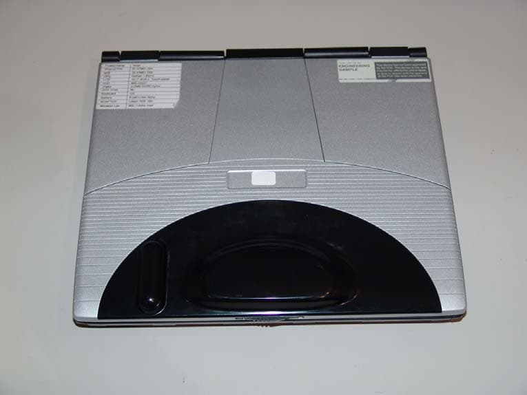
Click to zoom
Application Details
- Equipment Class
- PCB - PCS Licensed Transmitter
- Date of Grant
- Sep 10, 2006
- Application Purpose
- Original Equipment
- Date of Application
- Sep 10, 2006
- Equipment Note
- IX600-MC8765
- Frequency Range
- 826.40000000 - 846.60000000
- Country
- United States
Documents & Files
Document Text
Text extracted from the exhibit documents filed with the FCC. Open a document above to read the original.
Users Manual
Getting Started Congratulations on your purchase of the Itronix GoBook PRO II computer! Your new GoBook PRO II features the most innovative advances in portable computing technology. It combines state-of-the-art ergonomics with sophisticated architecture to provide you with a personal computer that is compact, powerful, and easy to use. Designed for a wide range of general, business, and personal productivity applications, the semi-rugged, wireless ready GoBook PRO II is an ideal choice wherever you need a computer; in the office, at home, and on the road. Your GoBook II is both expandable and portable, supporting the features you expect in a desktop computer but with the mobility of a laptop. This online document, GoBook PRO II Help, contains all the information you need to set up and use your new GoBook PRO II. For information on printing, navigating or otherwise using GoBook PRO II Help see the How to Use This Help System topics. Unpacking Your System Inside your packaging you will find: GoBook ® PRO II Help Page 1 of 100GoBook PRO II Help 5/16/2005file://C:\Documents%20and%20Settings\barvillj.ITRXNT1\Local%20Settings\Temp\~hh7... Standard Options Where to Look For Information Features This computer was designed with the user in mind. Here are just a few of its many features: Performance Multimedia Connectivity Human-centric design and ergonomics Expansion See Specifications for more information. The First Time. . . Before using your computer, install the battery and then attach the computer to AC power. Installing the battery: 72_0128_001 16 May 2005 © 2005 Itronix Corporation. All rights reserved. GoBook ® PRO II Help 72_0128_001 16 May 2005 © 2005 Itronix Corporation. All rights reserved. GoBook ® PRO II Help 1. Line up the battery connectors. 2. Press gently on the battery until it clicks into place. Page 2 of 100GoBook PRO II Help 5/16/2005file://C:\Documents%20and%20Settings\barvillj.ITRXNT1\Local%20Settings\Temp\~hh7... Attaching AC Power: Begin Using the Computer 3. Slide the battery locks toward the outside of the computer to lock the battery. 1. Connect the AC adapter power cord to the AC adapter. 2. Connect the AC adapter to the DC power port on the rear panel of your computer. 3. Connect the AC adapter power cord to a properly grounded AC outlet. NOTE It is recommended you use a quality surge protector . insert picture 1. Slide the display cover release latch to the right. 2. Open the display to a comfortable viewing angle. 3. Press the power switch to turn on the power. The POST (power-on self-test) routine executes and Windows begins loading. NOTE When using a battery pack for the first time, fully charge the battery, then Page 3 of 100GoBook PRO II Help 5/16/2005file://C:\Documents%20and%20Settings\barvillj.ITRXNT1\Local%20Settings\Temp\~hh7... Turning off Your Computer Turning off the computer properly is important to maintaining your computer. Select Start, Shut Down and follow the instructions on the screen. If you are going to be away from the computer for a short period, there are ways to conserve power without shutting down the system. See Power Saving Modes for details. NOTE If you are unable to shut down your computer normally, press and hold the power button more than four seconds to turn off the computer. If you turn off the computer and want to turn it on again, wait at least two seconds before powering up. CAUTION Shutting off the computer improperly may result in data loss. Loading Windows This section is for installing the Windows operating system only. If you are installing a different operating system, please check with your vendor for installation details. Your computer will begin loading Windows once you turn on the power. Wait a few seconds for Windows setup to load. The Windows setup will prompt you for the product key number. You can find the product key number on a sticker attached to the bottom of the computer. 1. Type your name, and, if applicable, the name of your company. 2. Read the End User's License Agreement. Click Next to accept it. 3. Enter the product key number. You can find this on the Certificate of Authenticity on a sticker attached to the computer. Click Finish . 4. The Start Wizar d will prompt you to set the date, and your local time. disconnect the adapter to use up the battery before recharging again. Perform this action twice to condition the battery pack. Calibrating the battery before use is also highly recommended. Refer to Power Management, for more information. 72_0128_001 16 May 2005 © 2005 Itronix Corporation. All rights reserved. GoBook ® PRO II Help Page 4 of 100GoBook PRO II Help 5/16/2005file://C:\Documents%20and%20Settings\barvillj.ITRXNT1\Local%20Settings\Temp\~hh7... Some software comes pre-loaded with Windows. New users can familiarize themselves with this software by selecting All Programs from the start menu, then clicking on programs to run them. CAUTION When you are installing the Windows operating system and enter the product key number, we strongly recommend connecting the AC adapter - DO NOT use battery alone to avoid warning messages. Startup Problems? If your computer does not operate, try these solutions. z Connect the AC adapter to charge the battery if it is not charged. NOTE The Power LED on the AC adapter should be lit as well as the External Power Indicator on the GoBook PRO II if the AC adapter is connected and functioning properly. Additionally, one of the power icons should appear in the task tray. z If the AC adapter is connected but the unit will still not turn on, make sure the electrical outlet you are using works. z Check to make sure the battery is installed and charged properly. z If the battery does not begin charging, remove the battery, connect the AC adapter, and turn on the computer by pressing the Power Button. Reinstall the battery. The Battery Indicator is solid orange while the battery is charging. The Troubleshooting section lists additional solutions you can try. Safety and Erg…
Text truncated - open the document above for the full version.
Cover Letter(s)
209 Dayton Street, Suite 205 Edmonds, WA 98020-3581 425 771-4482 425 486-1933 Fax August 15, 2006 Northwest EMC, Inc. 22975 NW Evergreen Parkway, #400 Hillsboro, OR 97124 % Vicki Albertson Re: Applicant: Itronix, Corporation FCC ID: KBCIX600-MC8765 1.) Limited Modular Certification for the embedded Sierra Wireless, Inc. Model: MC8765, PCI Express Mini-Card Model: MC8765, 3-G enabled EDGE, GPRS, and GSM, dual band UMTS, HSDPA data capability. 2.) Co-location with the FCC ID’s: KBCIX600-IWL, KBCIX600-BT and KBCIX600-IWLBT. TCB Committee, On behalf of Itronix Corporation we request a Limited Modular Certification for the Sierra Wireless PCI Express Mini-Card, Model: MC8765 embedded in the IX600 Rugged PC under rule Parts 22H & 24E. We also request that this Certification include co-location with the above referenced Limited Modular Certified Intentional radiators. Exhibits supporting this request are submitted with this application. We would like to reference the OEM, Sierra Wireless, Inc. Modular Certification test report prepared by CCS for all of the conducted test data. The radiated spurious and ERP/EIRP measurements made by NW EMC, Inc. would cover the integration of the MC8765 embedded module into the IX600 host with two new antenna combinations. The IX600 Vehicle Mount option extends many of the PC I/O ports and the switches the RF output of the WAN radio to an external antenna. Placing the IX600 in the cradle automatically causes the cradle contact board to switch the output of the MC8765 transmitter from the internal antenna located in the PC display, to and through the IX600 Vehicle Mount to an SMA connector and then to the external antenna. The external vehicular antenna sold by Itronix with this package is a 3 dBi gain antenna manufactured by MaxRad Model: BMLPVDB800/1900 along with the Model: LMR195 vehicle antenna ¾” magnetic mount with 17 ft of coax. Please let me know if you should require any further information. Best Regards, Rod Munro Agent, Itronix Corp. President, Spectrum Technology, Inc. [email protected]
Cover Letter(s)
Northwest EMC TCB Compliance Opinion Rev. 9/15/03 SPTE0026 Information about the Applicant Company Name Itronix Corporation Grantee Richard Sargent Address 12825 E. Mirabeau Parkway City, State, Zip Spokane Valley, WA 99216 Job Number SPTE0016 Model IX600-8765 FCC ID KBCIX600-8765 Agent Rod Munro Approval Type Original Equipment Class PCB - PCS Licensed Transmitter Rule Part 22/24 Industry Canada Information Model Industry Canada ID Rule Part Overview See Grantee provided cover letter. The applicant is making application using a radio that has been previously approved. Those items that are affected have been addressed in this application. Those items that have not been changed or affected are taken at face value as approved items. However, the test reports supporting that previous approval have been included in this filing for reference. Recommendation All items have been resolved and completed to my satisfaction; therefore I recommend this application for approval. Signature 9/7/2006 Dean Ghizzone, TCB Committee Northwest EMC TCB Compliance Opinion Rev. 9/15/03 SPTE0026 Findings Opinions Specification Requirements Description 47 Cfr 2.1033(c)(11) Internal and external photos Opinion The device meets the requirements of the rule. Discussion The client has provided the necessary exhibit. Reference Internal Photos.pdf, External Photos.pdf Specification Requirements Description 47 Cfr 24.52 RF Exposure Limits Opinion The device meets the requirements of the rule. Discussion The client has provided the necessary exhibit. Reference MPE Estimates.pdf Specification Requirements Description Labeling Labeling Requirements Opinion The device meets the requirements of the rule. Discussion The client has provided the necessary exhibit. Reference Label and Location.pdf Specification Requirements Description 15.109 Radiated emissions of the receiver Opinion The device meets the requirements of the rule. Discussion The client has provided the necessary exhibit. Reference Test Report Specification Requirements Description 22H and 24E Radiated Spurious Emissions Opinion The device meets the requirements of the rule. Discussion The client has provided the necessary exhibit. Reference Test Report Specification Requirements Description 22H and 24E ERP and EIRP of Fundamental Opinion The device meets the requirements of the rule. Discussion The client has provided the necessary exhibit. Reference Test Report Northwest EMC TCB Compliance Opinion Rev. 9/15/03 SPTE0026 Specification Requirements Description 15.107 Conducted Emissions Opinion The device meets the requirements of the rule. Discussion The client has provided the necessary exhibit. Reference Test Report
External Photos
Applicant: Itronix, Corporation FCC ID: KBCIX600-MC8765 1 External Photos IX600 Top View Bottom View FCC & IC ID Label Location Applicant: Itronix, Corporation FCC ID: KBCIX600-MC8765 2 IX600 Right Side - CRMA location (silver module in slot toward front of PC) IX600 Left Side Applicant: Itronix, Corporation FCC ID: KBCIX600-MC8765 3 IX600 Rear View IX600 Front Open Applicant: Itronix, Corporation FCC ID: KBCIX600-MC8765 4 IX600 Back Side of Display Open Right Side View Open Applicant: Itronix, Corporation FCC ID: KBCIX600-MC8765 5 External Photos CRMA Express Module housing the MC8765 Embedded Module CRMA Express Module Top Side CRMA Express Module Bottom SIM Card Side
ID Label/Location Info
Applicant: Itronix Corporation FCC ID: KBCIX600-MC8765 FCC and IC Identifier & Label Location Identifier label location shown below on the bottom of the IX600 Laptop Facsimile FCC and Industry Canada Identifier Labels applicable to the stand-alone model and the three co-located combinations are located on the four following pages: 1.) KBCIX600-MC8765, 1943A-IX600e 2.) KBCIX600-BT, 1943A-IX600a and KBCIX600-MC8765, 1943A-IX600e 3.) KBCIX600-IWL, 1943A-IX600a and KBCIX600-MC8765, 1943A-IX600e 4.) KBCIX600-IWLBT, 1943A-IX600a and KBCIX600-MC8765, 1943A-IX600e
Internal Photos
Applicant: Itronix, Corporation FCC ID: KBCIX600-MC8765 1 Internal Photos IX600 Top view, PC closed, display cover removed IX600 view back side of display upright WAN antenna center, GPS to right Applicant: Itronix, Corporation FCC ID: KBCIX600-MC8765 2 IX600 close up WAN antenna centered - GPS antenna on right side IX600 WAN radio visible (silver card in slot at front of PC) Applicant: Itronix, Corporation FCC ID: KBCIX600-MC8765 3 IX600 touch pad/keyboard cover flipped up, WAN radio located lower right side, WAN edge connector of module only partially visible ^ above ^ WAN location Applicant: Itronix, Corporation FCC ID: KBCIX600-MC8765 4 Internal Photos CRMA Express Module housing the MC8765 Embedded Module CRMA Express Module Top Side CRMA Express Module Bottom SIM Card Side Applicant: Itronix, Corporation FCC ID: KBCIX600-MC8765 5 CRMA Express Module with MC-8765 PCI Express Mini Card Internal Photos of the MC8765 Mini PCI Express Module are on the on the next two pages:
Operational Description
Applicant: Itronix Corporation FCC ID: KBCIX600-MC8765 Antenna Information Internal and External WAN Antenna Information FCC ID: KBCIX600-MC8765 Antenna Model Antenna Part No. Frequency (MHz) Antenna Type Antenna Gain (dBi) IX600 PRIMARYUMTS WWAN ANTENNA 59-0479-00xR 824 - 1880 Meander Line Antenna1.5 @ 850 IX600 PRIMARYUMTS WWAN ANTENNA 59-0479-00xR 824 - 1880 Meander Line Antenna-1.5 @ 1900 External – MaxRad 3 dBi Gain BMLPVDB800/1900806 - 960 Low profile vertical 3 External – MaxRad 3 dBi Gain BMLPVDB800/19001710-1990 Low profile vertical 3
RF Exposure Info
Applicant: Itronix, Corporation FCC ID: KBCIX600-MC8765, KBCIX600-BT, KBCIX600-IWL & KBCIX600-IWLBT 1 Compliance with 47 CFR 15.247(i) “Systems operating under the provisions of this section shall be operated in a manner that ensures that the public is not exposed to radio frequency energy levels in excess of the Commission's guidelines. See § 1.1307(b)(1) of this chapter.” The EUT will only be used with a separation distance of 20 centimeters or greater between the antenna and the body of the user or nearby persons and can therefore be considered a mobile transmitter per 47 CFR 2.1091 (b). Calculations are provided for each radio transmitting through its own internal antenna and optional external antenna. The total transmit power is less than 1.5 W (ERP), therefore the EUT is categorically excluded from routine environmental evaluation per 47 CFR 2.1091(c). The MPE estimates are as follows: Table 1 in 47 CFR 1.1310 defines the maximum permissible exposure (MPE) for the general population. The exposure level at a 20 cm distance from the EUT’s transmitting antenna is calculated using the general equation: S = (PG)/4πR 2 Where: S = power density (mW/cm 2 ) P = power input to the antenna (mW) G = numeric power gain relative to an isotropic radiator R = distance to the center of the radiation of the antenna (20 cm = limit for MPE estimates) PG = EIRP Solving for S, the maximum power densities 20 cm from the transmitting antennas are summarized in the tables on the following pages: Applicant: Itronix, Corporation FCC ID: KBCIX600-MC8765, KBCIX600-BT, KBCIX600-IWL & KBCIX600-IWLBT 2 MPE Estimates for Co-located Device FCC ID: KBCIX600-MC8765 Edge/GSM/GPRS/WCDMA/UMTS/HSDPA Antenna Type Antenna Part No. Transmit Frequency Max Peak Conducted Output Power Antenna Gain Min. Antenna Cable Loss Power Density @ 20 cm General Population Exposure Limit from 1.1310 Ratio of Power Density to the Exposure Limit (MHz) (mW) (dBi) (dB) (mW/cm) (mW/cm 2 ) Internal UMTS Skycross WAN 59-0479-001 1850.2 817 0.3 1.76 0.116 1 0.116 Internal UMTS Skycross WAN 59-0479-001 824.2 1611 2.7 0.89 0.486 0.56 0.885 Ext MaxRad BMLPVDB800/1900 1850.2 817 3 4.61 0.112 1 0.112 Ext MaxRad BMLPVDB800/1900 824.2 1611 3 2.45 0.364 0.560.662 Duty Cycle for GPRS (the worst case) is 25% Worst Case Ratio of Power Density to the Exposure Limit = 0.885 Duty Cycle not taken into consideration Applicant: Itronix, Corporation FCC ID’s: KBCIX600-MC8765, & KBCIX600-IWLBT 3 MPE Estimates for Co-located Device FCC ID: KBCIX600-IWLBT IEEE 802.11 (a) (b) g) Antenna Type Antenna Part No. Transmit Frequency Max Peak Conducted Output Power Antenna Gain Minimum Antenna Cable Loss Power Density @ 20 cm General Population Exposure Limit from 1.1310 Ratio of Power Density to the Exposure Limit (MHz) (mW) (dBi) (dB) (mW/c m 2 ) (mW/cm 2 ) PiFa MAIN 25.90215.001 5320 100.69 2.26 0 0.034 1 0.034 PiFa MAIN 25.90215.001 2462 92.9 2.41 0 0.032 1 0.032 Worst Case Ratio of Power Density to the Exposure Limit = 0.034 FCC ID: KBCIX600-IWLBT Bluetooth Radio Antenna Type Antenna Part No. Transmit Frequency Max Peak Conducted Output Power Antenna Gain Minimum Antenna Cable Loss Power Density @ 20 cm General Population Exposure Limit from 1.1310 Ratio of Power Density to the Exposure Limit (MHz) (mW) (dBi) (dB) (mW/c m 2 ) (mW/cm 2 ) Etenna's AccuWave EA2400 2402 0.85 3 0 0.0003 1 0.0003 Worst Case Ratio of Power Density to the Exposure Limit = 0.0003 Applicant: Itronix, Corporation FCC ID’s: KBCIX600-MC8765, & KBCIX600-IWLBT 4 Per Note 24 shown below, the Sum of Worst Case Power Ratios cannot exceed 1.0 GSM/GPRS WCDMA/Edge Worst Case Ratio of Power Density to the Exposure Limit 802.11a Radio Worst Case Ratio of Power Density to the Exposure Limit Bluetooth Worst Case Ratio of Power Density to the Exposure Limit Sum of Worst Case Ratios (Power Density to the Exposure Limit) FCC Limit for Sum of Worst Case Ratios 0.885 0.034 0.0003 0.9193 1.0 PASS
RF Exposure Info
Applicant: Itronix, Corporation FCC ID: KBCIX600-MC8765, KBCIX600-BT 1 Compliance with 47 CFR 15.247(i) “Systems operating under the provisions of this section shall be operated in a manner that ensures that the public is not exposed to radio frequency energy levels in excess of the Commission's guidelines. See § 1.1307(b)(1) of this chapter.” The EUT will only be used with a separation distance of 20 centimeters or greater between the antenna and the body of the user or nearby persons and can therefore be considered a mobile transmitter per 47 CFR 2.1091 (b). Calculations are provided for each radio transmitting through its own internal antenna and optional external antenna. The total transmit power is less than 1.5 W (ERP), therefore the EUT is categorically excluded from routine environmental evaluation per 47 CFR 2.1091(c). The MPE estimates are as follows: Table 1 in 47 CFR 1.1310 defines the maximum permissible exposure (MPE) for the general population. The exposure level at a 20 cm distance from the EUT’s transmitting antenna is calculated using the general equation: S = (PG)/4πR 2 Where: S = power density (mW/cm 2 ) P = power input to the antenna (mW) G = numeric power gain relative to an isotropic radiator R = distance to the center of the radiation of the antenna (20 cm = limit for MPE estimates) PG = EIRP Solving for S, the maximum power densities 20 cm from the transmitting antennas are summarized in the tables on the following pages: Applicant: Itronix, Corporation FCC ID: KBCIX600-MC8765, KBCIX600-BT 2 MPE Estimates for Co-located Device FCC ID: KBCIX600-MC8765 Edge/GSM/GPRS/WCDMA/UMTS/HSDPA Antenna Type Antenna Part No. Transmit Frequency Max Peak Conducted Output Power Antenna Gain Min. Antenna Cable Loss Power Density @ 20 cm General Population Exposure Limit from 1.1310 Ratio of Power Density to the Exposure Limit (MHz) (mW) (dBi) (dB) (mW/cm) (mW/cm 2 ) Internal UMTS Skycross WAN 59-0479-001 1850.2 817 0.3 1.76 0.116 1 0.116 Internal UMTS Skycross WAN 59-0479-001 824.2 1611 2.7 0.89 0.486 0.56 0.885 Ext MaxRad BMLPVDB800/1900 1850.2 817 3 4.61 0.112 1 0.112 Ext MaxRad BMLPVDB800/1900 824.2 1611 3 2.45 0.364 0.560.662 Duty Cycle for GPRS (the worst case) is 25% Worst Case Ratio of Power Density to the Exposure Limit = 0.885 Duty Cycle not taken into consideration Applicant: Itronix, Corporation FCC ID: KBCIX600-MC8765, KBCIX600-BT MPE Estimates for Co-Located Device FCC ID: KBCIX600-BT Bluetooth Radio Antenna Type Antenna Part No. Transmit Frequency Max Peak Conducted Output Power Antenna Gain Minimum Antenna Cable Loss Power Density @ 20 cm General Population Exposure Limit from 1.1310 Ratio of Power Density to the Exposure Limit (MHz) (mW) (dBi) (dB) (mW/c m 2 ) (mW/cm 2 ) Etenna's AccuWave EA2400 2402 0.85 3 0 0.0003 1 0.0003 Worst Case Ratio of Power Density to the Exposure Limit = 0.0003 Applicant: Itronix, Corporation FCC ID’s: KBCIX600-MC8765, KBCIX600-BT 4 Per Note 24 shown below, the Sum of Worst Case Power Ratios cannot exceed 1.0 GSM/GPRS WCDMA/Edge Worst Case Ratio of Power Density to the Exposure Limit Bluetooth Worst Case Ratio of Power Density to the Exposure Limit Sum of Worst Case Ratios (Power Density to the Exposure Limit) FCC Limit for Sum of Worst Case Ratios 0.8850 0.0003 0.8853 1.0 PASS
RF Exposure Info
Applicant: Itronix, Corporation FCC ID: KBCIX600-MC8765, KBCIX600-IWL 1 Compliance with 47 CFR 15.247(i) “Systems operating under the provisions of this section shall be operated in a manner that ensures that the public is not exposed to radio frequency energy levels in excess of the Commission's guidelines. See § 1.1307(b)(1) of this chapter.” The EUT will only be used with a separation distance of 20 centimeters or greater between the antenna and the body of the user or nearby persons and can therefore be considered a mobile transmitter per 47 CFR 2.1091 (b). Calculations are provided for each radio transmitting through its own internal antenna and optional external antenna. The total transmit power is less than 1.5 W (ERP), therefore the EUT is categorically excluded from routine environmental evaluation per 47 CFR 2.1091(c). The MPE estimates are as follows: Table 1 in 47 CFR 1.1310 defines the maximum permissible exposure (MPE) for the general population. The exposure level at a 20 cm distance from the EUT’s transmitting antenna is calculated using the general equation: S = (PG)/4πR 2 Where: S = power density (mW/cm 2 ) P = power input to the antenna (mW) G = numeric power gain relative to an isotropic radiator R = distance to the center of the radiation of the antenna (20 cm = limit for MPE estimates) PG = EIRP Solving for S, the maximum power densities 20 cm from the transmitting antennas are summarized in the tables on the following pages: Applicant: Itronix, Corporation FCC ID: KBCIX600-MC8765, and KBCIX600-IWL 2 MPE Estimates for Co-located Device FCC ID: KBCIX600-MC8765 Edge/GSM/GPRS/WCDMA/UMTS/HSDPA Antenna Type Antenna Part No. Transmit Frequency Max Peak Conducted Output Power Antenna Gain Min. Antenna Cable Loss Power Density @ 20 cm General Population Exposure Limit from 1.1310 Ratio of Power Density to the Exposure Limit (MHz) (mW) (dBi) (dB) (mW/cm) (mW/cm 2 ) Internal UMTS Skycross WAN 59-0479-001 1850.2 817 0.3 1.76 0.116 1 0.116 Internal UMTS Skycross WAN 59-0479-001 824.2 1611 2.7 0.89 0.486 0.56 0.885 Ext MaxRad BMLPVDB800/1900 1850.2 817 3 4.61 0.112 1 0.112 Ext MaxRad BMLPVDB800/1900 824.2 1611 3 2.45 0.364 0.560.662 Duty Cycle for GPRS (the worst case) is 25% Worst Case Ratio of Power Density to the Exposure Limit = 0.885 Duty Cycle not taken into consideration Applicant: Itronix, Corporation FCC ID’s: KBCIX600-MC8765, and KBCIX600-IWL 3 MPE Estimates for Co-located Device FCC ID: KBCIX600-IWL IEEE 802.11 (a) (b) g) Antenna Type Antenna Part No. Transmit Frequency Max Peak Conducted Output Power Antenna Gain Minimum Antenna Cable Loss Power Density @ 20 cm General Population Exposure Limit from 1.1310 Ratio of Power Density to the Exposure Limit (MHz) (mW) (dBi) (dB) (mW/c m 2 ) (mW/cm 2 ) PiFa MAIN 25.90215.001 5320 100.69 2.26 0 0.034 1 0.034 PiFa MAIN 25.90215.001 2462 92.9 2.41 0 0.032 1 0.032 Worst Case Ratio of Power Density to the Exposure Limit = 0.034 Applicant: Itronix, Corporation FCC ID’s: KBCIX600-MC8765, & KBCIX600-IWL 4 Per Note 24 shown below, the Sum of Worst Case Power Ratios cannot exceed 1.0 MC8765 GSM GRPS/WCDMA Worst Case Ratio of Power Density to the Exposure Limit 802.11a Radio Worst Case Ratio of Power Density to the Exposure Limit Worst Case Ratio of Power Density to the Exposure Limit Sum of Worst Case Ratios (Power Density to the Exposure Limit) FCC Limit for Sum of Worst Case Ratios 0.885 0.034 0.919 1.0 PASS
RF Exposure Info
Grantee: ITRONIX, Corporation FCC ID: KBCIX600-MC8765 1 Compliance with 47 CFR 15.247(i) “Systems operating under the provisions of this section shall be operated in a manner that ensures that the public is not exposed to radio frequency energy levels in excess of the Commission's guidelines. See § 1.1307(b)(1) of this chapter.” The EUT will only be used with a separation distance of 20 centimeters or greater between the antenna and the body of the user or nearby persons and can therefore be considered a mobile transmitter per 47 CFR 2.1091 (b). Calculations are provided for each radio transmitting through its own internal antenna and optional external antenna. The total transmit power is less than 1.5 W (ERP), therefore the EUT is categorically excluded from routine environmental evaluation per 47 CFR 2.1091(c). The MPE estimates are as follows: Table 1 in 47 CFR 1.1310 defines the maximum permissible exposure (MPE) for the general population. The exposure level at a 20 cm distance from the EUT’s transmitting antenna is calculated using the general equation: S = (PG)/4πR 2 Where: S = power density (mW/cm 2 ) P = power input to the antenna (mW) G = numeric power gain relative to an isotropic radiator R = distance to the center of the radiation of the antenna (20 cm = limit for MPE estimates) PG = EIRP Solving for S, the maximum power densities 20 cm from the transmitting antennas are summarized in the tables on the following pages: Grantee: ITRONIX, Corporation FCC ID: KBCIX600-MC8765 2 MPE Estimates for Self Co-located Device FCC ID: KBCIX600-MC8765 Edge/GSM/GPRS/WCDMA/UMTS/HSDPA Antenna Type Antenna Part No. Transmit Frequency Max Peak Conducted Output Power Antenna Gain Min. Antenna Cable Loss Power Density @ 20 cm General Population Exposure Limit from 1.1310 Ratio of Power Density to the Exposure Limit (MHz) (mW) (dBi) (dB) (mW/cm) (mW/cm 2 ) Internal UMTS Skycross WAN 59-0479-001 1850.2 817 0.3 1.76 0.116 1 0.116 Internal UMTS Skycross WAN 59-0479-001 824.2 1611 2.7 0.89 0.486 0.56 0.885 Ext MaxRad BMLPVDB800/1900 1850.2 817 3 4.61 0.112 1 0.112 Ext MaxRad BMLPVDB800/1900 824.2 1611 3 2.45 0.364 0.56 0.662 Duty Cycle for GPRS (the worst case) is 25% Worst Case Ratio of Power Density to the Exposure Limit = 0.885 Duty Cycle not taken into consideration
Test Report
Spectrum Technology IX600-MC8765 July 21, 2006 Report No. SPTE0026.1 Report Prepared By www.nwemc.com 1-888-EMI-CERT © 2006 Northwest EMC, Inc 22975 NW Evergreen Parkway Suite 400 Hillsboro, Oregon 97124 Certificate of Test Issue Date: July 21, 2006 Spectrum Technology Model: IX600-MC8765 Emissions Test Description Specification Test Method Pass Fail Radiated Emissions FCC 15.109(a) Class B:2005-10 ANSI C63.4:2003 Conducted Emissions FCC 15.107 Class B:2005-10 ANSI C63.4:2003 Modifications made to the product See the Modifications section of this report Approved By: Greg Kiemel, Director of Engineering This report must not be used to claim product certification, approval, or endorsement by NVLAP, NIST, or any agency of the federal government of the United States of America. Product compliance is the responsibility of the client, therefore the tests and equipment modes of operation represented in this report were agreed upon by the client, prior to testing. This Report may only be duplicated in its entirety. The results of this test pertain only to the sample(s) tested, the specific description is noted in each of the individual sections of the test report supporting this certificate of test. Northwest EMC Revision History Revision 05/05/03 Revision Number Description Date Page Number 00 None Northwest EMC Accreditations and Authorizations Revision 03/18/05 FCC: Accredited by NVLAP for performance of FCC radio, digital, and ISM device testing. Our Open Area Test Sites, certification chambers, and conducted measurement facilities have been fully described in reports filed with the FCC and accepted by the FCC in letters maintained in our files. Northwest EMC has been accredited by ANSI to ISO / IEC Guide 65 as a product certifier. We have been designated by the FCC as a Telecommunications Certification Body (TCB). This allows Northwest EMC to certify transmitters to FCC specifications in accordance with 47 CFR 2.960 and 2.962. NVLAP: Northwest EMC, Inc. is accredited under the United States Department of Commerce, National Institute of Standards and Technology, and National Voluntary Laboratory Accreditation Program for satisfactory compliance with the requirements of ISO/IEC 17025 for Testing Laboratories. The NVLAP accreditation encompasses Electromagnetic Compatibility Testing in accordance with the European Union EMC Directive 89/336/EEC, ANSI C63.4, MIL- STD 461E, DO-160D and SAE J1113. Additionally, Northwest EMC is accredited by NVLAP to perform radio testing in accordance with the European Union R&TTE Directive 1999/5/EEC, the requirements of FCC, and the RSS radio standards for Industry Canada. NVLAP LAB CODE 200629-0 NVLAP LAB CODE 200630-0 NVLAP LAB CODE 200676-0 Industry Canada: Accredited by NVLAP for performance of Industry Canada RSS and ICES testing. Our Open Area Test Sites and certification chambers comply with RSS 212, Issue 1 (Provisional) and have been filed with Industry Canada and accepted. Northwest EMC has been accredited by ANSI to ISO / IEC Guide 65 as a product certifier. We have been designated by NIST and recognized by Industry Canada as a Certification Body (CB) per the APEC Mutual Recognition Arrangement (MRA). This allows Northwest EMC to certify transmitters to Industry Canada technical requirements. CAB: Designated by NIST and validated by the European Commission as a Conformity Assessment Body (CAB) to conduct tests and approve products to the EMC directive and transmitters to the R&TTE directive, as described in the U.S. -…
Text truncated - open the document above for the full version.
Contact Information
Applicant
Ray Garcia(Agency Manager)
Test Firm
Northwest EMC, Inc.Greg Kiemel
Technical Specifications
| # | Rule Parts | Frequency Range | Power Output | Emission | Tolerance |
|---|---|---|---|---|---|
| 6 | 22H | 826.4 MHz - 846.6 MHz | 208.00 mW | 4M15F9W | 0.1 ppm |
Other Applications from General Dynamics Itronix Corporation

KBCIX-BR-51
Jan 20, 2008IX-BTBR51
Equipment Class
DSS - Part 15 Spread Spectrum Transmitter
KBCIX-MC8775
May 30, 2007IX-MC8775
Equipment Class
PCB - PCS Licensed Transmitter
KBCIX-4965AGN
May 21, 2007IX-4965AGN
Equipment Class
NII - Unlicensed National Information Infrastructure TX
KBCIX-AC595
Apr 19, 2007IX-AC595 DUAL-BAND CDMA/EV-DO PCMCIA MODEM CARD
Equipment Class
PCB - PCS Licensed Transmitter
KBCIX-NW620
Mar 13, 2007IX-NW620 CDMA/EV-DO
Equipment Class
PCB - PCS Licensed Transmitter