KBCXC6250SB300XC6250, CDPD wireless handheld terminal
General Dynamics Itronix Corporation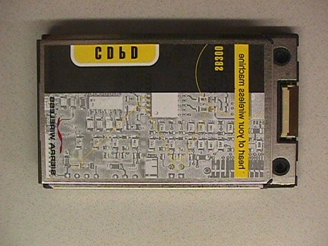
Click to zoom
Application Details
- Equipment Class
- TNB - Licensed Non-Broadcast Station Transmitter
- Date of Grant
- Aug 24, 1999
- Application Purpose
- Original Equipment
- Date of Application
- Apr 11, 1999
- Equipment Note
- XC6250, CDPD wireless handheld terminal
- Frequency Range
- 824.00000000 - 849.00000000
- Country
- United States
Documents & Files
Document Text
Text extracted from the exhibit documents filed with the FCC. Open a document above to read the original.
Cover Letter(s)
Apr 28, 1999 Federal Communications Commission Authorization and Standards Division 7435 Oakland Mills Rd. Columbia, M.D. 21046 Dear Sir/Madam: Re: FCC ID EA93836 and Request for Confidentiality We hereby request that the documentation listed below, submitted with our application for type acceptance, be withheld from public disclosure. This request is made under the provisions of Section 0.457(d) of the Commission’s Rules, and Section 552(b)(4) of the Freedom of Information Act. We cite trade secrets as the reason and purpose of the request. 1. SB300 modem schematics (sb300_schematic.pdf) 2. SB300 detailed circuit description (sb300_dcd.pdf) Sincerely, Richard Utting OEM Systems Engineer
Cover Letter(s)
Apr 28, 1999 Federal Communications Commission Authorization and Standards Division 7435 Oakland Mills Rd. Columbia, M.D. 21046 Sir/Madam, Sierra Wireless Incorporated has tested this transmitter in accordance with the requirements contained in the appropriate Commission Regulations. To the best of my knowledge, these tests were performed using measurement procedures consistent with the Industry or Commission standards and demonstrates that the equipment complies with the published standard. We are unable to warrant against unpublished changes in requirements. The applicable rules are listed in the following test report. The Open Area Test Site used for these measurements is located at Fluke Park, Mulkilteo, Washington. Site information required by Public Notice 24541 in accordance with ANSI C634-1992 was filed with the FCC Authorization and Evaluation Division Sampling and Measurements Branch in July 1994. Sincerely Trent McKeen RF Engineer
Cover Letter(s)
Apr 28, 1999 Federal Communications Commission Authorization and Standards Division 7435 Oakland Mills Rd. Columbia, M.D. 21046 Dear Sir/Madam: Re: FCC ID EA93836 submission note This submission for FCC part 22 is being filed for the integration of the Sierra Wireless Inc., wireless modem SB300 which has FCC approval (N7NOEM2) already granted for the modem as a stand alone unit. This submission is for the SB300 modem integrated into an Itronix Corporation XC6250 ruggedized laptop. Sincerely, Richard Utting OEM Systems Engineer
External Photos
APPLICATION FOR Type Acceptance EXTERNAL PHOTOS Sierra Wireless Inc. FCC ID: EA93836 MODEL: SB300 Modem Integrated into the XC6250 Prepared by: Sierra Wireless Inc. #150 - 13575 Commerce Parkway Richmond, B.C. V6V 2L1 Canada Apr .23, 1999 Figure 1: Modem External View – Top Side Figure 2: Modem External View – Bottom Side Figure 3: Itronix XC6250 laptop
ID Label/Location Info
APPLICATION FOR Type Acceptance ID Label Location Photos Sierra Wireless Inc. FCC ID: EA93836 MODEL: SB300 Modem Integrated into the XC6250 Prepared by: Sierra Wireless Inc. #150 - 13575 Commerce Parkway Richmond, B.C. V6V 2L1 Canada Apr. 28, 1999 FCC ID: EA93836 2 Figure 1: Location of the FCC Approval label FCC ID: EA93836 3 Figure 2: Location of the FCC Approval label FCC ID: EA93836 4 Figure 3: Location of the FCC Approval label
RF Exposure Info
1 Report on Evaluation of Compliance of a Ruggedised Laptop Computer Itronix XC6250 with a SB300 series Wireless Modem, with the FCC 96-326 Guidelines for Evaluating Environmental Effects of Radiofrequency Radiation Prepared for: Sierra Wireless, Inc. 13575 Commerce Parkway Richmond, B.C. Canada, V6V-2L1 M.Okoniewski, Ph.D., Assoc. Professor Dept. of Electrical and Computer Engineering, University of Calgary May, 1999 2 Introduction This report provides results of a numerical evaluation of the maximum specific absorption rate (SAR) produced in the human tissue by a ruggedised Laptop Computer, series XC6250, with a SB300 series modem, here-upon called a device under test or test device. The evaluation is performed for the worst case configurations of the test device and the user’s head with respect to the FCC 96-326 Guidelines. The purpose of the evaluation is to establish compliance with the Federal Communication Commission FCC 96-326 Guidelines for Evaluating the Environmental Effects of Radiofrequency Radiation, ET Docket No. 93-62, adopted August 1, 1996. The information submitted shows that even under the worst case conditions the device under test meets FCC requirements, specifically: • whole-body averaged SAR not exceeding 0.08 W/kg, • SAR averaged over 1 gram of tissue in the head not exceeding 1.6 W/kg. • SAR averaged over 10 gram of tissue in the hands not exceeding 4.0 W/kg The format of the information provided follows the list of technical items for SAR evaluation outlined in Supplement C (Edition 97-01) to OET Bulletin 65 (Edition 97-01). Test Device Setup and System Uncertainties General Information • FCC ID: KBCXC6250SB300 (SB300 Integration), KBCXC6250SB320 (SB320 Integration) • device category: portable, • RF exposure environment: uncontrolled, • test method: computation with the finite difference time domain (FDTD) method 3 • affirmative statement: the device under test complies with FCC adopted limits; “For the device user, under the worst-case realistic exposure condition 1g averaged SAR in the head does not exceed the prescribed value of 1.6 W/kg, 10g averaged SAR in hands does not exceed 4.0 W/kg, and the whole-body average SAR does not exceed 0.008 W/kg for the device user. It is unrealistic to expect that a bystander can place his/her head closer to the antenna than the user, while the device is in use”. Antenna Description • antenna type: metal strip in protective dielectric sheath • antenna location on device: top, right-hand side of the screen • antenna dimensions: length metal strip: length 150 mm, width 8.5 mm, thickness 0.3mm; protective sheath length 155 mm, width 10.2 mm, thickness 3mm. • antenna configuration: non-retractable, vertical Test Signal and Output Power • test signal: CW, no time averaging used, frequency 836MHz • output power: maximum 600 mW (specified by the manufacturer). Test Position and Conditions • head and hands position: the model of the human head is placed as close to the device screen as judged possible for a shortsighted person, who wants to read the text on the screen. Under normal circumstances, the usual and conformable work position is much further away from the computer screen. The head is slightly tilted, as illustrated in Fig.1. Simplified hands are also included, to test if the SAR in hands does not exceed the prescribed limits. As the device is equipped with a “touch screen’ capabilities, test position include one hand touching the screen in the top right corner – 4 the closest distance between antenna and the hand under normal operation. Note that the presence of the hands results in lower power deposition into the operator’s head. The following test configurations were considered: 1. Head only, reflecting worst case scenario for head exposure 2. Hands only, for maximum exposure of the hands – hands flat on the keyboard 3. Hands only, for maximum exposure of the hands; left hand on the keyboard, right hand touching top, right corner of the screen, simulating touch-screen operator action (the computer has touch-screen capabilities) 4. Head and hands in position 2 5. Head and hands in position 3 • device position: Screen is set to be at normal angle to the body of the computer (keyboard) , which results in the worst case scenario for the antenna. (Usually, the screen is tilted 120 degrees with respect to the keyboard, thus increasing the distance between the antenna and the head); • antenna position: plugged into the computer in a vertical position, connected internally with the radio-modem with a coax cable. Computation Uncertainty • description of computational uncertainties: there are several potential sources of error. The estimated uncertainty associated with them is summarized below: Anatomical model of the head; anatomy differences10 % Dielectric properties of tissues 5 % Antenna modeling 3 % Device modeling 3 % FDTD: stair-casing, dielectric properties averaging 1 % SAR averaging 1 % • estimated total uncertainty12 % 5 Information for SAR Computation Basic FDTD Parameter Description • Domain size: (orientation of the coordinates shown in Fig. 1) ÿ for the computations without the head: 300 x 250 x 410 mm, not includin PML layers. Cell size 2.5 x 2.5 x 2.5 mm 3 , time step 4.77 ps ÿ for the computations without the head: 300 x 490 x 410 mm, not including PML layers. Cell size 2.5 x 2.5 x 2.5 mm 3 , time step 4.77 ps • ABC type: PML, 7 layers, parabolic, reflection –50dB • Source excitation: CW with 50 Ω resistive Voltage source, applied at the antenna connector • Total time steps: 2800 • Method used to determine steady state: the following observation criteria are used: (i) electric field probes are place in tissue close to the expected peak SAR (determined after preliminary run), close to the antenna feed and in a farthest corner of the computational domain; the simulation is stopped, when the field changes are less than 0.2% (in spectral domain). (ii) the antenna input impedance changes are below 2%. Both condition…
Text truncated - open the document above for the full version.
RF Exposure Info
July 6, 1999 Federal Communications Commission Authorization and Standards Division 7435 Oakland Mills Rd. Columbia, M.D. 21046 Ref: FCC ID KBCXC6250SB300 (EA93836) - Correspondence Reference Number:8339 & FCC ID KBCXC6250SB320 (EA93837) - Correspondence Reference Number:8340 Dear Sir/Madam, This communication is in response to your request for additions to the Itronix user guide that includes warning information for a by-stander to be in excess of 20cm from the transmitting antenna. I have had a request from Itronix that this distance be shortened to 5cm for a by-stander as per a previous Itronix FCC submission (FCC ID:KBCXC6250RIM901) This used the same lap-top (XC6250) with a different modem integration with a higher output transmitter (1.7W) as compared to 0.6W for this Sierra Wireless modem integration submission. I have included a copy of the Itronix Technical Bulletin for the XC6250 (RIM Modem) previous integration to see if this is acceptable for this integration with a Sierra Wireless modem. Sincerely Richard Utting, C.Eng. OEM Systems Integrator Sierra Wireless Inc. 13575 Commerce Parkway Suite 150 Richmond, BC V6V 2L1 Canada Tel: (604) 231-1116/Fax: (604) 231-1109 Email: [email protected] Internet: www.sierrawireless.com
RF Exposure Info
Technical Bulletin 801 South Stevens • P.O. Box 179 • Spokane, WA 99210 • 509.624.6600 • 800.441.1309 WARNINGThe Itronix Corporation Model X-C 6250 Ruggedized Wireless Laptop was found to be compliant with FCC RF exposure requirements for the uncontrolled/general population exposure environment with these operating conditions. While the device is operating, its antenna must be at least 5 cm from all persons in order to comply with the FCC RF exposure limit. Operators should ensure that when this device operates, its antenna is at least 5 cm from nearby persons for meeting RF exposure limits. 97-0047-003 02/99 X-C 6250 Computer RF Antenna Placement FCC regulations require that radio operators comply with the following. RF Modems RF Modems and Vehicle Mounted Antennas FCC regulations require that users of vehicle-mounted antennas must use only antennas authorized for use with the X-C 6250 computer in order to meet FCC RF exposure limits. Please contact Itronix for a list of approved vehicle-mounted antennas. For mounting installation and/or mounting instructions for these types of antennas, see the instructions that accompany each antenna. Placement of the vehicle mount antenna 1. Measure and identify an area 20 cm (8 inches) in from the edges of the vehicle roof. 2. Place the vehicle mount antenna within that area. To maximize RF performance, position the antenna in the center of the vehicle roof. WARNINGImproper installation and/or operating configurations of permanent and magnetic vehicle mount antennas may cause FCC RF exposure limits to be exceeded. Vehicle mount antennas must be placed at least 20cm from operators and bystanders. Side View Front View
RF Exposure Info
Certification Report on Specific Absorption Rate (SAR) Experimental Analysis Sierra Wireless Inc for Itronix Corporation X-C 6250 with SB300 Date: 26 July, 1999 51 Spectrum Way Nepean ON K2R 1E6 Tel: (613) 820-2730 Fax: (613) 820-4161 email: [email protected] This report shall not be reproduced, except in full, without the express written approval of APREL Laboratories. Page 1 of 25© APREL Project #: SRAB- XC6250 SB300-3266 51 Spectrum WayTel. (613) 820-2730 Nepean, Ontario, K2R 1E6Fax (613) 820 4161 e-mail: [email protected] CERTIFICATION REPORT Subject:Specific Absorption Rate (SAR) Experimental Analysis Product:Itronix Corporation Ruggedized Wireless Laptop with Sierra Wireless SB300 transmitter Model:Itronix Corporation X-C 6250 Client:Sierra Wireless Inc. for Itronix Corporation Address:13575 Commerce Parkway Suite 150 Richmond, B.C. V6V 2L1 Project #:SRAB-XC6250 SB300-3266 Prepared by:APREL Laboratories 51 Spectrum Way Nepean, Ontario K2R 1E6 Tested by____________________________Date: _________________ Heike Wünschmann, C.E.T. Submitted by____________________________Date: _________________ Dr. Paul G. Cardinal Director, Laboratories Approved by_____________________________Date: _________________ Dr. Jacek J. Wojcik, P. Eng. Page 2 of 25© APREL Project #: SRAB- XC6250 SB300-3266 51 Spectrum WayTel. (613) 820-2730 Nepean, Ontario, K2R 1E6Fax (613) 820 4161 e-mail: [email protected] FCC ID:KBCXC6250SB300 Applicant:Itronix Corporation Equipment:Ruggedized Wireless Laptop Model:Itronix Corporation X-C 6250 with Sierra Wireless SB300 transmitter Standard:FCC 96 –326, Guidelines for Evaluating the Environmental Effects of Radio- Frequency Radiation ENGINEERING SUMMARY This report contains the results of the engineering evaluation performed on an Itronix Corporation X-C 6250 Ruggedized Wireless Laptop operating with a built in Sierra Wireless SB300 radio transmitter. The measurements were carried out in accordance with FCC 96- 326. The X-C 6250 Ruggedized Wireless Laptop was evaluated for its nominal maximum power level of 630 mW (28 dBm). The SB300 version of the X-C 6250 was tested at high, middle, and low frequencies, with the maximum SAR coinciding with the peak performance RF output power of channel 384 (middle, 836 MHz). Test data and graphs are presented in this report. This unit as tested, and as it will be marketed and used (with a warning in the manual to keep bystanders at least 15.2 mm from the antenna), is found to be compliant with the FCC 96-326 requirement, for an uncontrolled RF exposure environment. Page 3 of 25© APREL Project #: SRAB- XC6250 SB300-3266 51 Spectrum WayTel. (613) 820-2730 Nepean, Ontario, K2R 1E6Fax (613) 820 4161 e-mail: [email protected] TABLE OF CONTENTS 1.Introduction........................................................................................................................4 2.Applicable Documents.......................................................................................................4 3.Equipment Under Test.......................................................................................................4 4.Test Equipment..................................................................................................................5 5.Test Methodology..............................................................................................................5 6.Test Results........................................................................................................................6 6.1.Transmitter Characteristics........................................................................................6 6.2.SAR Measurements....................................................................................................7 7.Analysis............................................................................................................................10 8.Conclusions......................................................................................................................11 Appendix A..............................................................................................................................12 Appendix B..............................................................................................................................18 Appendix C..............................................................................................................................21 Appendix D..............................................................................................................................22 Appendix E...............................................................................................................................25 Page 4 of 25© APREL Project #: SRAB- XC6250 SB300-3266 51 Spectrum WayTel. (613) 820-2730 Nepean, Ontario, K2R 1E6Fax (613) 820 4161 e-mail: [email protected] 1. INTRODUCTION Tests were conducted to determine the Specific Absorption Rate (SAR) of a sample of an Itronix Corporation X-C 6250 Ruggedized Wireless Laptop which incorporates a Sierra Wireless SB300 radio transmitter. These tests were conducted at APREL Laboratories’ facility located at 51 Spectrum Way, Nepean, Ontario, Canada. A view of the SAR measurement setup can be seen in Appendix A Figure 1. This report describes the results obtained. 2. APPLICABLE DOCUMENTS The following documents are applicable to the work performed: 1) FCC 96-326, Guidelines for Evaluating the Environmental Effects of Radio- Frequency Radiation 2) ANSI/IEEE C95.1-1992, IEEE Standard for Safety Levels with Respect to Human Exposure to Radio Frequency Electromagnetic Fields, 3 kHz to 300 GHz. 3) ANSI/IEEE 95.3-1992, IEEE Recommended Practice for the Measurement of Potentially Hazardous Electromagnetic Fields – RF and Microwave. 4) OET Bulletin 65 (Edition 97-01) Supplement C (Edition 97-01), “Evaluating Compliance with FCC Guidelines for Human Exposure to Radio Frequency Electromagnetic Fields”. 3. EQUIPMENT UNDER TEST • Itro…
Text truncated - open the document above for the full version.
Test Report
APPLICATION FOR TYPE ACCEPTANCE Sierra Wireless Inc. FCC ID: EA93836 MODEL: SB300 Modem Integrated into the XC6250 Prepared by: Sierra Wireless Inc. #150 - 13575 Commerce Parkway Richmond, B.C. V6V 2L1 Canada Apr. 26, 1999 FCC ID: EA93836 3 Table Of Contents Table Of Contents_____________________________________________3 Letter of Submittal and Compliance_______________________________4 Applicant Introduction_________________________________________5 SB300 Operational Modes____________________________________________________5 Expository Statement 2.983 – Modem Detailed Circuit Description_____6 SB300 Modem Logic General Description_______________________________________6 Description of Terminology___________________________________________________6 Detail Circuit Description____________________________________________________6 MCU_____________________________________________________________________7 MEMORY________________________________________________________________8 DSP______________________________________________________________________8 DRAIN___________________________________________________________________8 Logic Board I/O Description__________________________________________________9 Electrical Specifications – Logic Board________________________________________10 SB300 Radio General Description____________________________________________11 SB320 Radio Electrical Specifications_________________________________________12 SB300 Radio Block Diagram_________________________________________________13 User Manual Pages With FCC Disclaimers_______________________16 Calculation of Necessary Bandwidth for FCC ID: EA93836__________19 For CDPD 19.2Kbps Transmission (emission type FXW)_________________________19 Performance Test Data________________________________________20 RF Output Power (2.985)___________________________________________________20 Modulation Characteristics (2.987)____________________________________________21 Occupied Bandwidth (2.989)_________________________________________________22 Spurious Emissions at Antenna Terminals (2.991)_______________________________25 Field Intensity Measurements of Spurious Radiation (2.993)_______________________29 Operation Stability Performance (2.995)_______________________________________30 Test Equipment List__________________________________________33 FCC Sample Label___________________________________________34 Finished Product Label:_____________________________________________________34 Finished Product Label Location:_____________________________________________35 Owners Manual________________________________________Enclosed Equipment Photographs_________________________________Enclosed Schematics ___________________________________________Enclosed FCC ID: EA93836 4 Letter of Submittal and Compliance Apr. 26, 1999 Federal Communications Commission Authorization and Standards Division 7435 Oakland Mills Rd. Columbia, M.D. 21046 Sir/Madam, Sierra Wireless Incorporated has tested this transmitter in accordance with the requirements contained in the appropriate Commission Regulations. To the best of my knowledge, these tests were performed using measurement procedures consistent with the Industry or Commission standards and demonstrates that the equipment complies with the published standard. We are unable to warrant against unpublished changes in requirements. The applicable rules are listed in the following test report. Sincerely Trent McKeen RF Engineer FCC ID: EA93836 5 Applicant Introduction Sierra Wireless, Inc., located in Richmond, B.C., Canada, designs and manufactures wireless data modems for use on Cellular networks. The company was incorporated in May of 1993 around a core engineering staff with special expertise in development of products for use in commercial mobile data systems. SB300 Operational Modes CDPD The modem transmits using CDPD signaling only. The modulation used in this case is GMSK at a single data rate of 19.2kbps. Deviation in this mode is factory adjusted to 4.8kHz peak ±5%. FCC ID: EA93836 6 Expository Statement 2.983 – Modem Detailed Circuit Description The SB300 modem is a wireless modem, which operates on CDPD networks. The product operates as a stand alone modem which may connect to host device (such as a personal computer) through an available serial port. The SB300 modem consists of 2 different subcircuits which are packaged together in a PCMCIA Type III housing. These circuits are 1. Modem Logic 2. Radio Each subcircuit is discussed separately in the subsequent sections. SB300 Modem Logic General Description Description of Terminology CDPDcellular digital packet data DSPdigital signal processor EEPROMelectrically erasable programmable read-only memory MCUmicro controller unit Detail Circuit Description The logic board can be divided into various subsystems: MCU, DSP, and Memory. Figure 2-1 shows a block diagram of system. FCC ID: EA93836 7 Figure 2-1: Logic Board Block Diagram MCU The MCU subsystem is responsible for the communicating with the host and running application software. It talks to the DSP through the DRAIN ASIC interface. The subsystem consists of an MC68LC302 CPU, a reset generator, and a 32kHz crystal. The MC68LC302 has an MC68000 core with two independent serial communication controllers (SCC) and various general-purpose parallel port pins. The first serial port is used as a debug port and the second is used for the host interface. The debug port has only the RX, TX and GND lines while the host port has full handshaking with DCD, RX, TX, DTR, DSR, RTS, CTS, RI, and ground. The CPU has a 16-bit bus but the upper eight bits have been disabled to allow the use of 8-bit memory devices. The CPU has 20 address lines and 4 chip select lines that allow it to address up to 4 Mbytes. Address line A0 is used as WEH (Write Enable High) in 8 bit wide data bus mode. The CPU uses two I/O lines to implement an I 2 C protocol to talk to the EEPROM, one I/O line to reset the EEPROM Memory 1024x8…
Text truncated - open the document above for the full version.
Contact Information
Applicant
Ray Garcia(Agency Manager)
Technical Contact
Sierra Wireless Inc.Richard Utting
[email protected](604) 231-1116
Suite 150, 13575 Commerce Parkway · Richmond, BC · Canada
Non-Technical Contact
Sierra Wireless Inc.Richard Utting
[email protected](604) 231-1116
Test Firm
Intertek Testing Services NA Inc.John Quigley
Technical Specifications
| # | Rule Parts | Frequency Range | Power Output | Emission | Tolerance |
|---|---|---|---|---|---|
| 1 | 22.901(d) | 824 MHz - 849 MHz | 631.00 mW | 31K5FXW | 2.5000000000 ppm |
Other Applications from General Dynamics Itronix Corporation

KBCIX-BR-51
Jan 20, 2008IX-BTBR51
Equipment Class
DSS - Part 15 Spread Spectrum Transmitter
KBCIX-MC8775
May 30, 2007IX-MC8775
Equipment Class
PCB - PCS Licensed Transmitter
KBCIX-4965AGN
May 21, 2007IX-4965AGN
Equipment Class
NII - Unlicensed National Information Infrastructure TX
KBCIX-AC595
Apr 19, 2007IX-AC595 DUAL-BAND CDMA/EV-DO PCMCIA MODEM CARD
Equipment Class
PCB - PCS Licensed Transmitter
KBCIX-NW620
Mar 13, 2007IX-NW620 CDMA/EV-DO
Equipment Class
PCB - PCS Licensed Transmitter