KCH510R2Utility Meter Transceiver
Sensus Metering Systems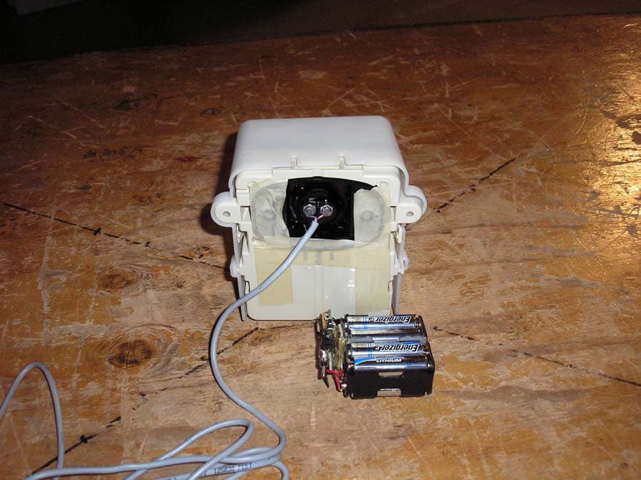
Click to zoom
Application Details
- Equipment Class
- DTS - Digital Transmission System
- Date of Grant
- Nov 13, 2006
- Application Purpose
- Original Equipment
- Date of Application
- Nov 13, 2006
- Equipment Note
- Utility Meter Transceiver
- Frequency Range
- 904.60000000 - 925.40000000
- Company
- Sensus Metering Systems
- Country
- United States
Documents & Files
Document Text
Text extracted from the exhibit documents filed with the FCC. Open a document above to read the original.
Users Manual
AMR-XXX Sensus RadioRead Model 510R2 – Non Pit Unit Installation Instructions-Draft Page 1 of 4 The following information contains installation instructions for the Sensus Model 510R2 MXU. Note: This installation sheet is only for installation of the Sensus Model 510R2. For instructions on installing other AMR devices, please request and refer to the individual installation instruc- tion for those devices. The Model 510R2 MXU is designed for non pit, non submersible applications and is available for both a single port and dual port operation. The Model 510R2 can be mounted indoors or outdoors where it is not subject to submergence. The Model 510R2 is not intended for outdoor meter pits or vaults. The unit can be installed with either a TouchCoupler connection or wire connection. Please refer to AMR-326 for compatibility. 1. Sensus TouchPad 2. TouchPad Cover Assembly Complete 3. TouchPad Cover 4. TouchPad Fastener 5. TouchPad Cover Locking Clip 6. Model 510R2 Radio (Front View) 7. Model 5102 Radio TouchCoupler Enabled Assembly (Rear View with TouchPad Cover) Single Port – TouchCoupler Installation 1. Perform a TouchRead on TouchPad(s) to insure TouchRead to the encoder works. 2. Taking a completely assembled Model 5102 Radio and Touch- Coupler Spacer with TouchPad Cover, align the TouchPad Cover over an installed Sensus TouchPad. Important General Information Definitions 1 2 6 7 3 4 5 TouchCoupler - Installation Instructions 3. Place the unit over the TouchPad and press firmly until secure. 4. For additional support (optional), open the MXU door and pre- drill the holes designed to fasten the unit to the wall. (Fastener holes are located above the battery). 5. Secure the unit to the wall with screws. 6. Once unit is secured with the screws, close the door of the MXU and tighten security screw until unit is firmly sealed. 7. Once the unit is closed and secured, begin the activation process. (See Activate Radio section). 8. Coil excess wire and then secure to the body of the meter or service line in a presentable manner. Single Port - Remote TouchCoupler Installation Remote TouchCoupler installations are an option when a direct TouchCoupler (Sensus only) connection cannot be completed due to physical limitations. Before proceeding with the installation of a remote TouchCoupler application, be sure to find a location free from obstacles that would interfere with the connection from the TouchPad Cover to the MXU. ● Wire stripping tool ● Screwdriver - Small standard head for terminal connections ● SR II security screw socket with 1/4" nut driver or ratchet wrench ● Power drill and bit (1/4") ● 8 x 1" sheet metal screws 1. Find a suitable location for the installation where the TouchPad Cover and MXU installation will be free from interference. Note: If TouchPad is not already installed, install TouchPad allowing enough room for the TouchPad Cover to be securely placed over the installed TouchPad. Recommended Tools and Materials amr_321.fm Page 1 Tuesday, July 18, 2006 3:55 PM AMR-XXX 2. Perform a TouchRead on TouchPad(s) to insure TouchRead to the encoder works. 3. Place the remote TouchPad Cover firmly over the Sensus TouchPad until secured. 4. Once the TouchPad Cover is secured on the TouchPad, find a location close to the TouchPad Cover to install the MXU. 5. Place the MXU at the location for installation, with the door open, mark the location to pre-drill the holes designed to fasten the unit to the wall. (Fastener holes are located above the battery). 6. Remove the MXU from the wall and use a 1/4" drill bit to pre-drill the fastener holes. 7. Place the unit on the wall and align the pre-drilled holes with the fastener locations. 8. Secure the unit to the wall with screws. 9. Connect the wires from the TouchPad Cover to the coordinating port terminals in the MXU labeled TouchCoupled. Note: Red and black wires are non-polarized. 10. Once all the connections are complete, close the door of the MXU and tighten security screw until unit is firmly sealed. 11. Once the units are secured, begin the activation process. (See Activate Radio section). BATTERY Blue Black & White Red Green Black Red Green Black RadioRead PORT 1 PORT 2 Touch Coupled Touch Coupled Sensus Metering Systems Uniontown, PA 15401 Model 510R Pt. No. 539-61-537-51006T M510R-D2-CMB-CMB-T Patent Pending. Date 06/05 Dual Port – TouchCoupler Installation ● Wire stripping tool ● Screwdriver - Small standard head for terminal connections ● SR II security screw socket with 1/4" nut driver or ratchet wrench ● Power drill and bit (1/4") ● 8 x 1" sheet metal screws 1. Perform a TouchRead on TouchPad(s) to insure TouchRead to the encoder works. 2. For new installations of dual ports, find a suitable location for an installation where two TouchPads can be installed that will be free from interference. The optimum distance should be less than 12" otherwise wires may require field splicing. (For existing TouchPad connections and second port is added, select a location for the second TouchPad installation that will be free from interference). 3. Determine which of the two TouchPads will use the TouchPad Cover only and which will use the TouchCoupler unit as the pri- mary connection. Note: If TouchPad is not already installed, install TouchPad allowing enough room for the TouchPad Cover to be securely placed over the installed TouchPad. 4. Place the remote TouchPad Cover firmly over the Sensus Touch- Pad until secured. 5. With the MXU door open, place the MXU over the second Touch- Pad location and press firmly until unit is secured to the Touch- Pad. For additional support (optional), pre-drill the holes designed to fasten the unit to the wall. (Fastener holes are located above the battery). Secure the unit to the wall with screws. Note: If not already installed, install the second TouchPad allowing enough room to connect the MXU to the TouchPad. Recommended Tools and Materials Installation Instructions-Draft Page 2 of 4 Sensus RadioRead Model…
Text truncated - open the document above for the full version.
Cover Letter(s)
tel: 650-726-1263 fax: 650-726-1252 [email protected] Thomas N. Cokenias EMC &Radio Approvals Test & Consulting Services for Commercial, Military, International Compliance P.O. Box 1086 El Granada, CA 94018 Compliance Certification Services 14 November 2006 561F Monterey Road Morgan Hill, CA 95037 Attention: Application Examiner Reviewing Engineer Applicant: Sensus Metering Systems FCC ID: KCH510R2 900MHz DTS Transceiver Re: Request for confidentiality per 0.457 and 0.459 of the Rules To whom it may concern, Request is hereby submitted, on behalf of my client Sensus Metering Systems to withhold from public review certain portions of the application for equipment certification for the referenced FCC identifier. In particular, the following sections of the application and report are requested to be kept confidential: Block Diagrams Schematic Operational Description Rationale for request for confidentiality: Sensus has invested considerable time and materials in research and development to produce the referenced product. Disclosure of the confidential portions of this application to competitors would give them competitive advantage in developing similar products. If you have questions or need further information, please contact the undersigned. Sincerely, THOMAS N. COKENIAS EMC Consultant Agent for Sensus Metering Systems
Cover Letter(s)
1 Helen Zhao Subject: FW: Sensus Metering Systems, FCC ID: KCH510R2, Assessment NO.: AN06T6273, Notice# 1 510R2 conf.pdf510R2FCCreportRe v1.1.pdf From: Thomas Cokenias [mailto:[email protected]] Sent: Tuesday, November 14, 2006 6:46 AM To: Helen Zhao Subject: Re: Sensus Metering Systems, FCC ID: KCH510R2, Assessment NO.: AN06T6273, Notice#1 Hi Helen, All three questions answered below, answer follows question. best regards Tom Question #1: The test report (page 7) shows test data for FCC ID: KCH510RU. The confidentiality letter shows FCC ID: KCH510RU as well. The rest of the filing shows FCC ID: KCH510R2. Please clarify what is the correct FCC ID. ANS1 The correct FCC ID is KCH510R2. I have attached corrected test report and corrected confidentiality letter. Question #2: The limits listed on page 7 of the test report are confusing. If the compliance at 1.8GHz band was based on an RF conducted emission measurement, then the peak limit is 20dBc from fundamental, not the same as the fundamental. Please update the report. ANS2 I have corrected and clarified p7 to show the -20 dBc limit, as well as the FCC ID and model number. Question #3: The user manual does not contain RF exposure statement. Please update the user manual. ANS3 The following KDB responses indicate that for a very low duty cycle device such as this one (<1% in 6 minute time frame), no RFx information is required in user manual: This inquiry 840762 was inserted into Knowledge Database from an email sent directly to an FCC staff member. Please submit all future inquiries through this Knowledge Database system. Our original response in KDB 848176 was processed using our automated assignment method, where due to the original Inquiry Categories as registered it was not routed to staff members that normally prepare replies for RF exposure related matters. A supplemental response has been sent in KDB 848176. Due to the relatively low power and transmitting duty factor for certain types of utility meter transmitters, TCB and FCC application processing procedures were adjusted in May 2003 to forego listing separation distances on grant certificates for such fixed mounted 2 devices. Best regards Tom
External Photos
Sensus Metering Systems Inc. FCC ID: KCH510R2 External Photographs Front Side Rear
ID Label/Location Info
Sensus Metering Systems Inc. FCC ID: KCH510R2 FCC ID label and location FCC ID: KCH510R2 Model 510R2 This device complies with Part 15 of the FCC Rules. Operation is subject to the following two conditions: (1) This device may not cause harmful interference, and (2) This device must accept any interference received, including interference than may cause undesired operation IC: 2220A-510R2
Internal Photos
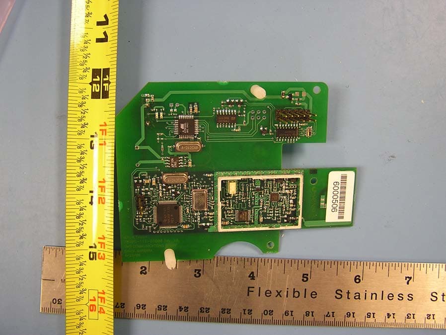
Sensus Metering Systems Inc. FCC ID: KCH510R2 Internal Photographs Board Top Board bottom
Test Report
Report No. 06PR049 Rev 1.1 FCC ID: KCH510R2 Sensus Metering Systems Sensus 510R2 Meter Transmitter Unit 1 of 56 900MHz DTS EMISSIONS TEST REPORT FOR A LOW POWER TRANSMITTER I. GENERAL INFORMATION Requirement: Federal Communications Commissions Test Requirements: 15.205, 15.207, 15.209, 15.247 Applicant: Sensus Metering Systems FCC ID: KCH510R2 II. DESCRIPTION OF EQUIPMENT UNDER TEST (EUT) The Sensus Model 510R2 MXU (Meter Transceiver Unit) FCC ID: KCH510R2 IC: 2220A-510R2 is a Radio Frequency transceiver unit operating under CFR47 Part 15 of the FCC rules. The Model 510R2 incorporates a part 15.247 Direct Sequence Spread Spectrum Transmitter operating in the 902 to 928 MHz ISM band, and a Part 15 AM Receiver operating in the 952 or 956 MHz MAS bands. The MXU uses spread spectrum techniques for remote water meter reading. The 510R2 will be used for non water pit applications (i.e. side of the house installations). The product transmits meter readings to a vehicle mounted or hand-held mobile data collection devices. The product receives a wake-up signal from the licensed transmitter in the mobile collection system; the 510R2 spread spectrum transmitter sends short bursts of data. A lithium battery powers the EUT; the battery has an expected life of 20 years. Transmitter Specification TX Power 24.37 dBm max. Frequency of operation 904.6-925.4 MHz Data Rate 15.625 Kbps in <50ms burst 6 dB bandwidth 1.2 MHz Power source lithium battery Software/firmware version: 2R105271 III. TEST DATES AND TEST LOCATION Testing was performed 10-11 October 2006. All tests were performed at: Compliance Certification Services 561F Monterey Road Morgan Hill, CA 95037 T.N. Cokenias 14 November 2006 EMC Consultant/Agent for Sensus Metering Systems Report No. 06PR049 Rev 1.1 FCC ID: KCH510R2 Sensus Metering Systems Sensus 510R2 Meter Transmitter Unit 2 of 56 900MHz DTS Report Revision History Revision No. Description Revised by Date - Original issue T. Cokenias 11 Oct 2006 1.1 Correct typos p7 T. Cokenias 14 Nov 2006 Report No. 06PR049 Rev 1.1 FCC ID: KCH510R2 Sensus Metering Systems Sensus 510R2 Meter Transmitter Unit 3 of 56 900MHz DTS 15.203 Antenna connector requirement The antenna is permanently attached to the product. For antenna conducted tests, a unit was modified by disconnecting the printed circuit antenna and replacing it with a 50 ohm coaxial cable connection terminated at one end with an SMA connector. 15.204 Antenna description The meter transceiver uses a printed circuit folded dipole antenna: Antenna description Gain printed ckt antenna 4.0 dBi (max) 0.0 dBi (average) TEST PROCEDURES All tests were performed in accordance with the applicable procedures called out in the following documents, unless otherwise noted: 1) ANSI C63.4 – 2003, American National Standard for Methods of Measurement of Radio-Noise Emissions from Low-Voltage Electrical and Electronic Equipment in the Range of 9 kHz to 40 GHz 2) FCC Public Notice 97-114, Guidance on Measurements for Direct Sequence Spread Spectrum Systems Report No. 06PR049 Rev 1.1 FCC ID: KCH510R2 Sensus Metering Systems Sensus 510R2 Meter Transmitter Unit 4 of 56 900MHz DTS TEST EQUIPMENT TEST EQUIPMENT LIST Name of EquipmentManufacturerModel No.Serial No.Due Date RF Filter SectionAgilent / HP85420E3705A002562/4/07 EMI Receiver, 9 kHz ~ 2.9 GHzAgilent / HP8542E3942A002862/4/07 Antenna, Horn 1 ~ 18 GHzETS3117352344/22/07 Preamplifier, 1 ~ 26 GHzAgilent / HP8449B3008A009318/1/07 Antenna, Bilog 30 MHz ~ 2 GhzSunol SciencesJB1A1210038/13/07 Spectrum Analyzer 3 Hz ~ 44 GHzAgilent / HPE4446AMY433601125/3/07 Active Loop AntennaEMCO65029202-272211/7/06 Report No. 06PR049 Rev 1.1 FCC ID: KCH510R2 Sensus Metering Systems Sensus 510R2 Meter Transmitter Unit 5 of 56 900MHz DTS TEST RESULTS Radiated Emissions Test Requirement: 15.205, 15.247 Out of Band Measurements Test Requirement: 15.247 Radiated Test Set-up, 1-26 GHz 1-4m 3m EUT preamplifier Fig. 1 Measurement Equipment Used: Spectrum Analyzer, 9 kHz-26.5 GHz Biconolog antenna Horn antenna, 1-18 GHZ Pre-amplifier, 1 – 26.5 GHz High pass filter, fp = 1500 MHz Test Procedures 1. The EUT was placed on a wooden table resting on a turntable on the test site. A water meter was connected to the appropriate ports as a typical load. The search antenna was placed 3m from the EUT. The EUT antenna was mounted vertically as per normal installation. 2. The turntable was slowly rotated to locate the direction of maximum emission at each emission falling in the restricted bands of 15.205. Report No. 06PR049 Rev 1.1 FCC ID: KCH510R2 Sensus Metering Systems Sensus 510R2 Meter Transmitter Unit 6 of 56 900MHz DTS 3. Radiated emissions were investigated for a LOW channel, a MID channel, and HIGH channel. Emissions were investigated to the 10 th harmonic. 4. Once maximum direction was determined, the search antenna was raised and lowered in both vertical and horizontal polarizations. The maximum readings so obtained are recorded in the data listed below. Test Results: Worst case results are presented. Refer to data sheets below. Restricted band emissions meet 54 dBuV/m. Other undesired emissions from the transmitter meet the -20 dBc requirement in 15.247(c). All emissions not reported were more than 20 dB below limits or were below noise floor of measuring system. FCC Radiated Emissions Limits S ectio n 15.205 Restricted bands of operation. (a) Excep t as shown in paragraph (d) of this section, only spurious emissions are permit ted in any of the frequency bands listed below: MHz MHz MHz GHz 0.090 - 0.110 0.495 - 0.505 (1) 2.1735 - 2.1905 4.125 - 4.128 4.17725 - 4.17775 4.20725 - 4.20775 6.215 - 6.218 6.26775 - 6.26825 6.31175 - 6.31225 8.291 - 8.294 8.362 - 8.366 8.37625 - 8.38675 8.41425 - 8.41475 12.29 - 12.293 12.51975 - 12.52025 12.57675 - 12.57725 13.36 - 13.41 16.42 - 16.423 16.69475 - 16.69525 16.80425 - 16.80475 25.5 - 25.67 37.5 - 38.25 73 - 74.6 74.8 - 75.2 108 - 121.94 123 - 138 149.9 - 150.05 156.52475 - 156.52525 156.7 - 156.…
Text truncated - open the document above for the full version.
Test Setup Photos
Sensus Metering Systems Inc. FCC ID: KCH510R2 Test Set-up Photographs Antenna port conducted emissions Radiated emissions, open area test site Above 1 GHz except for TX 3 rd harmonic emissions Radiated Emissions, anechoic chamber Below 1 GHz and 3 rd harmonic TX emissions Touchcoupler and Universal Programmer interface test setup
Contact Information
Applicant
Richard Daniel(Director, Engineering NPI and Project Management)
Test Firm
Compliance Certification ServicesBarbara Judge
Technical Specifications
| # | Rule Parts | Frequency Range | Power Output |
|---|---|---|---|
| 1 | 15C | 904.6 MHz - 925.4 MHz | 274.00 mW |
Other Applications from Sensus Metering Systems
KCHMXU530T
Aug 22, 2006Radio Transceiver for Electric Meter
Equipment Class
DTS - Digital Transmission System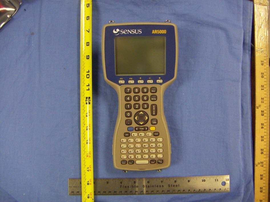
KCHAR5002
Jun 13, 2006Utility Meter RF Transceiver
Equipment Class
DXT - Part 15 Low Power Transceiver, Rx Verified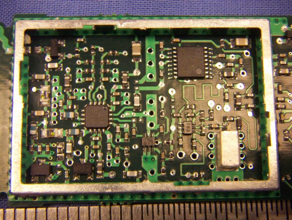
KCH520R
Jun 28, 2005900MHz DTS RF Module
Equipment Class
DTS - Digital Transmission System
KCHGS0003
Jan 19, 2005AUTOMATIC GAS METER TRANSMITTER
Equipment Class
DTS - Digital Transmission System
KCHGS0001
Jan 19, 2005AUTOMATIC GAS METER TRANSMITTER
Equipment Class
DTS - Digital Transmission System