KCH520R900MHz DTS RF Module
Sensus Metering Systems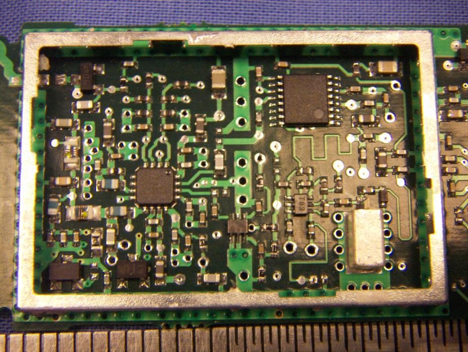
Click to zoom
Application Details
- Equipment Class
- DTS - Digital Transmission System
- Date of Grant
- Jun 28, 2005
- Application Purpose
- Original Equipment
- Date of Application
- Jun 28, 2005
- Equipment Note
- 900MHz DTS RF Module
- Frequency Range
- 904.60000000 - 925.40000000
- Company
- Sensus Metering Systems
- Country
- United States
Documents & Files
Document Text
Text extracted from the exhibit documents filed with the FCC. Open a document above to read the original.
Users Manual
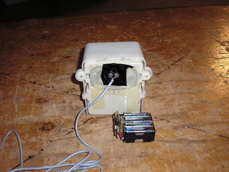
Model 510 Installation Instructions 2 Definitions 1 – Sensus TouchPad 2 – TouchPad Cover 3 – TouchPad Cover, Tinnerman Type Fastener, TouchPad Locking Clip 4 – Model 510 Radio (Front View) 5 – Model 510 Radio (Rear View with knockout) 6 – Model 510 Radio and TouchCoupler Spacer with TouchPad Cover 1 23 456 3 Table of Contents Single Port – TouchCoupler Installation____________________________________4 Dual Port – TouchCoupler Installation_____________________________________5 Single and Dual Port – Wired Installation___________________________________6 Activate Radio__________________________________________________________7 Appendix A:___________________________________________________________9 Appendix B: Regulatory Information_____________________________________12 4 Single Port – TouchCoupler Installation 1) While Model 510 Radio and TouchCoupler Spacer with TouchPad Cover all still assembled, align the TouchPad Cover over the Sensus TouchPad that is secured to the wall and press on whole assembly. 2) For additional support, open Model 510 Radio door and screw two screws using the holes located above the battery compartment. 3) Once secured, activate unit (see activation section). 5 Dual Port – TouchCoupler Installation 1. First choose which Sensus TouchPad will be covered remotely. Place the remote the TouchPad Cover over the Sensus TouchPad. 2. While Model 510 Radio and TouchCoupler Spacer with TouchPad Cover all still assembled, align the TouchPad Cover over the Sensus TouchPad that is secured to the wall and press on whole assembly. 3. For additional support, open Model 510 Radio door and screw two screws using the holes located above the battery compartment. 4. With the door still open, run the wire from the remote TouchPad Cover through the bottom of the Model 510 Radio and attach to appropriate terminal screws. 5. Once all connections are complete, activate unit (see activation section). 6 Single and Dual Port – Wired Installation 1. Open Model 510 Radio door. 2. Secure Model 510 Radio to a wall utilizing the screw holes above the battery compartment. 3. Run the register wires through the bottom of the Model 510 Radio and connect to the appropriate terminals. 4. Once all registers are connected, activate unit (see activation section). 7 Activate Radio Note: if no meters are connected to this radio, the radio will not activate. 1.) Once all meters are connected, the radio must be activated in order for it to perform its function. To activate, using a TouchReader or Model 4090 AutoGun, attempt a TouchRead on the Programming/TouchRead port (See picture below). Once TouchRead is activated, the radio will determine what is connected to this unit automatically. This may take up to 3-6 seconds depending on if this unit is dual port capable and what encoders are connected to it. TouchReader 2.) The TouchReader will beep once indicating that the radio acknowledged the TouchRead and is now detecting what is connected. 3.) After waiting ~3 seconds, attempt another TouchRead, if a read error occurs, the radio is still in detect mode. Repeat this step again in 3 more seconds. 4.) If successful detection, it should provide either a TouchRead reading (Sensus only) or a single beep to indicate that the encoder is connected but TouchRead is not supported via the radio 5.) If detection is unsuccessful, the TouchRead will beep once and restart the activation similar to step 2 above. AutoGun (ID type set to Factory ID – see AutoGun manual for instructions) 2.) The AutoGun will beep and display for the ID “MXUGPTC0”. This indicates that the radio acknowledged the TouchRead is in mode “0” which is inactive. This will start the detecting process. 3.) After waiting ~3 seconds, attempt another TouchRead, if a read error occurs, the radio is still in detect mode. Repeat this step again in 3 more seconds. 4.) If successful detection, the AutoGun will display either a TouchRead reading (Sensus only) or Programming / TouchRead Port (Sensus Logo) 8 • ID: MXUGPTC1 – which means a TouchRead was attempted on an unsupported meter (Neptune). • ID: MXUGPTC2 – which means that the port was configured for a meter type that supports TouchRead (Sensus only) but there was no response from the meter. 5.) If unsuccessful detection, the TouchRead will start the activation process again. The ID on the AutoGun will display MXUGPTC0 similar to the step 2 above. Note: Once the radio is activated and it detected what is connected, the only way to change its configuration as to what is connected is to deactivate the radio using a programming tool and re-activate the radio or use a programming tool to reprogram the port manually. Warning... Programming a port manually will not allow the unit to perform an automatic detection on that port unless reset to “AutoDetect”. The activation process will not reset the port type. 9 Appendix A: The following photos show how the PCB is oriented and installed into an enclosure. 10 11 12 Appendix B: Regulatory Information FCC Information to User: Changes or modifications not expressly approved by Sensus Metering Systems could void the user's authority to operate the equipment. In order to meet FCC’s RF exposure limits in section 1.1307 of the Rules, a minimum separation of 20 cm must be maintained between the antenna of this device. The antenna(s) used for this transmitter must not be co-located or operating in conjunction with any other antenna or transmitter.
Users Manual
Model 520 Installation Instructions 2 Definitions 1 – HDPE Radio 2 – Boot 3 – TouchCoupler TR/PL Adaptor (TouchCoupler enabled units only) 4 – Pit Lid Housing 5 – Pit Locking Nut 6 – Boot Locking Clip 4 5 1 2 6 3 3 Table of Contents Step 1 Disassemble 520 Unit______________________________________________4 Step 2 Inserting the Pit Lid Housing________________________________________5 Step 3 Securing the Pit Lid Housing to the Pit Lid_____________________________6 Step 4 Inserting the Radio Device in the Pit Lid Housing_______________________7 Step 5 Connecting meters to the radio_______________________________________8 Appendix A:__________________________________________________________12 Appendix B: Regulatory Information_____________________________________14 4 Step 1 Disassemble 520 Unit 1.) Disassemble the model 520 unit to begin the installation procedure. Unlock the radio device by pressing down on the two tabs on the Boot Locking Clip facing the port side connections. Once the tabs are depressed, slide the Boot Locking Clip partially out until the Boot Locking Clip disengages from the Pit Lid Housing. 2.) Slide out the HDPE Radio and Boot from the Pit Lid Housing. 3.) Remove the Pit Locking Nut from the underneath of the Pit Lid Housing by turning the Nut to the left. Sample pit lid is shown below: 5 Step 2 Inserting the Pit Lid Housing Place the Pit Lid Housing thru the pre-drilled hole in the top of the pit lid. Pit Lid Housing Inserted Through Pit Lid (Top View) Pit Lid Housing Inserted Through Pit Lid (Bottom View) 6 Step 3 Securing the Pit Lid Housing to the Pit Lid Place the Pit Locking Nut at the bottom of the Pit Lid Housing aligning the Pit Locking Nut with the shaft of the Pit Lid Housing. Tighten the Pit Locking Nut by turning to the right until the unit is firmly secured against the bottom of the pit lid. (See picture below) Securing the Pit Lid Housing to the Pit Lid 7 Step 4 Inserting the Radio Device in the Pit Lid Housing 1.) Insert the HDPE Radio with Boot into the cavity of the Pit Lid Housing (See picture below) 2.) Align the Boot with the slot located on the bottom of the Pit Lid Housing to secure the unit. 3.) To lock the unit into place, push Boot Locking Clip (opposite of the tabs) until tabs are engaged and locked. The endpoint is then inserted into the Pit Lid Housing: Insertion of the Endpoint into the Pit Lid Housing 8 Step 5 Connecting meters to the radio TouchCoupler (Sensus Only) 1.) Grasp the TRPL housing and place into Port 1 of the TouchCoupler TR/PL Adaptor until secured. (See picture below) 2.) Repeat process into Port 2 if needed. 9 Wired Units (Sensus, MultiRead Module (RadioRead Only), Neptune) Sensus Encoder 1.) Gel cap the red wire from the encoder to the red wire on the reading port (either port 1 or port 2 – if available). 2.) Gel cap the green wire from the encoder to the green wire on the reading port. 3.) Gel cap the black wire from the encoder to the black wire on the reading port. MultiRead Module 1.) Gel cap encoders to the MultiRead Module per the instructions sheet for the MultiRead Module (AMR-306). 2.) Once all encoders are connected to the MultiRead Module, gel cap the red wire from the MultiRead Module to the red wire on the reading port (either port 1 or port 2 – if available). 3.) Gel cap the green wire from the MultiRead Module to the green wire on the reading port. 4.) Gel cap the black wire from the MultiRead Module to the black wire on the reading port. Neptune Encoder 1.) Gel cap the red wire from the Neptune encoder to the green wire on the reading port (either port 1 or port 2 – if available). 2.) Gel cap the green wire from the Neptune encoder to the black wire on the reading port. 3.) Gel cap the black wire from the Neptune encoder to the red wire on the reading port. 10 Step 6 Activate Radio Note: if no meters are connected to this radio, the radio will not activate. 1.) Once all meters are connected, the radio must be activated in order for it to perform its function. To activate, using a TouchReader or Model 4090 AutoGun, attempt a TouchRead on the Programming/TouchRead port (See picture below). Once TouchRead is activated, the radio will determine what is connected to this unit automatically. This may take up to 3-6 seconds depending on if this unit is dual port capable and what encoders are connected to it. TouchReader 2.) The TouchReader will beep once indicating that the radio acknowledged the TouchRead and is now detecting what is connected. 3.) After waiting ~3 seconds, attempt another TouchRead, if a read error occurs, the radio is still in detect mode. Repeat this step again in 3 more seconds. 4.) If successful detection, it should provide either a TouchRead reading (Sensus only) or a single beep to indicate that the encoder is connected but TouchRead is not supported via the radio. 5.) If detection is unsuccessful, the TouchRead will beep once and restart the activation similar to step 2 above. AutoGun (ID type set to Factory ID – see AutoGun manual for instructions) 2.) The AutoGun will beep and display for the ID “MXUGPTC0”. This indicates that the radio acknowledged the TouchRead is in mode “0” which is inactive. This will start the detecting process. 3.) After waiting ~3 seconds, attempt another TouchRead, if a read error occurs, the radio is still in detect mode. Repeat this step again in 3 more seconds. 4.) If successful detection, the AutoGun will display either a TouchRead reading (Sensus only) or Programming / TouchRead Port 11 • ID: MXUGPTC1 – which means a TouchRead was attempted on an unsupported meter (Neptune). • ID: MXUGPTC2 – which means that the port was configured for a meter type that supports TouchRead (Sensus only) but there was no response from the meter. 5.) If unsuccessful detection, the TouchRead will start the activation process again. The ID on the AutoGun will display MXUGPTC0 similar to the step 2 above. Note: Once the radio is activated and it detected what is connected, the …
Text truncated - open the document above for the full version.
Cover Letter(s)
Sensus Metering Systems FCC ID:KCH520R Request for transmitter limited modular approval Transmitter Module Characteristics ItemRequirementsEUT 1Have its own RF shieldingDevice is equipped with Metal shielding to cover RF section. Refer to external photos 2Have buffered modulation/data inputs (if such inputs are provided), All inputs to the modules are buffered through logic or microprocessor inputs. 3Have it own power supply regulationNo 4Meet the antenna requirements of Section 15.203 Antenna is traces on PCB max 2.2 dBi 5Be tested in a stand-alone configuration, i.e., the antenna, AC or DC power and data input/output lines must be connected to the module but, the module must not be inside another case during testing EUT was tested in a stand-alone configuration with a test jig. 6Be labeled with its own FCC ID number, and if the FCC ID is not visible when the module is installed inside another device, then the outside of the device into which the module is installed must also display a label referring to the enclosed module. One of label is to be placed on the module and the other label is to be placed on the outside of system. Refer to FCC ID label format and location file. 7The modular transmitter is manufactured so that the user cannot influence the operation of the transmitter that will operate outside of the scope of the regulations. The EUT will be incorporated into Sensus products by Sensus or manufacturers under contract to Sensus. Module is not sold to users 8Address compliance with the Commission's RF exposure limits in Sections 1.1310 and 2.1093. In addition, spread spectrum transmitters operating under Section 15.247 are required to address RF exposure compliance in accordance with Section 15.247(b)(4). Calculation shows MPE distance of approximately 7.4 cm
Cover Letter(s)
tel: 650-726-1263 fax: 650-726-1252 [email protected] Thomas N. Cokenias EMC &Radio Approvals Test & Consulting Services for Commercial, Military, International Compliance P.O. Box 1086 El Granada, CA 94018 Compliance Certification Services17 June 2005 561F Monterey Road Morgan Hill, CA 95037 Attention: Application Examiner Reviewing Engineer Applicant: Sensus Metering Systems FCC ID: KCH520R 900MHz DTS RF Module To whom it may concern, Request is hereby submitted, on behalf of my client Sensus Metering Systems to withhold from public review certain portions of the application for equipment certification for the referenced FCC identifier. In particular, the following sections of the application and report are requested to be kept confidential: Block Diagrams Schematic Operational Description Rationale for request for confidentiality: Sensus has invested considerable time and materials in research and development to produce the referenced product. Disclosure of the confidential portions of this application to competitors would give them competitive advantage in developing similar products. _ If you have questions or need further information, please contact the undersigned. Sincerely, THOMAS N. COKENIAS EMC Consultant Agent for Sensus Metering Systems
Cover Letter(s)
1 Helen Zhao Subject:FW: Sensus Metering Systems, FCC ID: KCH520R, Assessment NO.: AN05T4885, Notice#1 From: Compliance Certification Services Client Sent: Sunday, June 26, 2005 9:01 PM To: Helen Zhao Subject: Sensus Metering Systems, FCC ID: KCH520R, Assessment NO.: AN05T4885, Notice#1 1, Calibration data has been submitted to the website 2, Corrected report has been submitted to the website 3. A new psd measurement was made and is included in the corrected test report submitted to the website 4, An agent authorization letter has been submitted to the website 5. The revised label/label location document has been uploaded to the website 6. This product will only be installed in host devices designed, controlled, specified, and manufactured by Sensus 7. User manuals have been modified to include the required 15.21 and 15.247 RF exposure information thanks and best regards Tom Cokenias -----Original Message----- From: Compliance Certification Services [mailto:[email protected]] Sent: Wednesday, June 22, 2005 5:44 PM To: Helen Zhao Subject: Sensus Metering Systems, FCC ID: KCH520R, Assessment NO.: AN05T4885, Notice#1 Question #1: Please include calibration date of each test equipment into the test report. Question #2: Page 1 & 19 of the test report indicate the low channel is 903.8MHz, however all the measurment at low channel was done at 904.6MHz. Please clarify which is correct and update the test report accordingly. Question #3: The PPSD HIGH channel plot shows "IF overload", please resubmit a valid plot. Question #4: Please submit an Agent Authorization Letter. Question #5: The modular approval cover letter says: "One of label is to be placed on the module and the other label is to be placed on the outside of system. Refer to FCC ID label format and location file." However, the FCC ID label format shows one label that will be put on the module. Please show how to label the host device when the module is installed in (label format and location). Question #6: Please advise whether the module will be installed in the host devices NOT manufacturered by Sensus Metering Systems. If so, please include the information how to label the host device into the user manual Question #7: Please revise user manual to include user information as required by FCC15.21 and RF exposure statement as required by FCC15.247(i). 2 Best Regards, Helen Zhao The items indicated above must be submitted before processing can continue on the above referenced application. Failure to provide the requested information within 30 days of the original e-mail date may result in application dismissal and forfeiture of the filing fee. Also, please note that partial responses increase processing time and should not be submitted. Any questions about the content of this correspondence should be directed to the e-mail address listed below the name of the sender.
Cover Letter(s)
Description of Model Difference Model name Model Difference 520R Used in water meter pit application. Radio enclosure designed to install into water meter pits. Refer to user installation guide for more detail. 510R Used in non-pit application. Radio enclosure is a generic design for multiple types of installations. Refer to user installation guide for more detail.
External Photos
Sensus Metering Systems FCC ID: KCH520R 902-928 MHz DTS Radio Module for Water Utility Meters Product Photographs Top view Under shield Bottom view
ID Label/Location Info
Sensus Metering Systems FCC ID: KCH520R 902-928 MHz DTS Radio Module for Water Utility Meters Product Photographs NOTE: All Sensus products that incorporate this radio module are required to have the following wording clearly visible on the exterior surface of a product, and easily visible to the customer at time of sale: On host device(when the module is installed inside the host) CONTAINS FCC ID: KCH520R FCC ID: KCH520R Operation is subject to the following two conditions: (1) This device may not cause harmful interference, and (2) This device must accept any interference received, including interference that may cause undesired operation
Internal Photos
Sensus Metering Systems FCC ID: KCH520R 902-928 MHz DTS Radio Module for Water Utility Meters Product Photographs Top view Under shield Bottom view
Test Report
FCC ID: KCH520R Sensus 520R Meter Transceiver Module 1 of 41 900MHz DTS EMISSIONS TEST REPORT FOR A LOW POWER TRANSMITTER I. GENERAL INFORMATION Requirement:Federal Communications Commissions Test Requirements: 15.205, 15.207, 15.209, 15.247 Applicant:Sensus Metering Systems FCC ID: KCH520R II. DESCRIPTION OF EQUIPMENT UNDER TEST (EUT) The Sensus FCC ID: KCH520R is a digital transmission system (DTS) operating under the requirements in FCC Part 15. 247. The Model 510R/520R incorporates a part 15.247 Direct Sequence Spread Spectrum Transmitter operating in the 902 to 928 MHz ISM band, and a Part 15 AM Receiver operating in the 952 or 956 MHz MAS bands. The MXU uses spread spectrum techniques for remote water meter reading. Transmitter Specification TX Power24.15 dBm max. Frequency of operation 904.6-925.4 MHz Data Rate15.625 Kbps in <80ms burst 6 dB bandwidth1.15 MHz Power source3.6 V lithium thionyl chloride battery Radio firmwareMXU4 GP-TC v0.0.4 Test software nameMXU4T III. TEST DATES AND TEST LOCATION Testing was performed 16-17 June 2005. All tests were performed at: Compliance Certification Services 561F Monterey Road Morgan Hill, CA 95037 T.N. Cokenias17 June 2005 EMC Consultant/Agent for Sensus Metering Systems FCC ID: KCH520R Sensus 520R Meter Transceiver Module 2 of 41 900MHz DTS 15.203 Antenna connector requirement The antenna is permanently attached to the product. For antenna conducted tests, a unit was modified by disconnecting the printed circuit antenna and replacing it with a 50 ohm coaxial cable connection terminated at one end with an SMA connector. 15.204 Antenna description The meter transceiver uses a printed circuit folded dipole antenna: Antenna descriptionGain printed ckt antenna2.2 dBi TEST PROCEDURES All tests were performed in accordance with the applicable procedures called out in the following documents, unless otherwise noted: 1) ANSI C63.4 – 2003, American National Standard for Methods of Measurement of Radio-Noise Emissions from Low-Voltage Electrical and Electronic Equipment in the Range of 9 kHz to 40 GHz 2) FCC Public Notice 97-114, Guidance on Measurements for Direct Sequence Spread Spectrum Systems FCC ID: KCH520R Sensus 520R Meter Transceiver Module 3 of 41 900MHz DTS TEST RESULTS Radiated Emissions Test Requirement: 15.205, 15.247 Out of Band Measurements Test Requirement: 15.247 Measurement Equipment Used: Agilent 4446A Spectrum Analyzer, 9 kHz-40 GHz Sunol Sciences JB1 Biconolog antenna EMCO 3115 Horn antenna, 1-18 GHZ Miteq NSP2600-SP pre-amplifier, 1 – 26.5 GHz IFI High pass filter, fp = 1500 MHz Radiated Test Set-up, 1-26 GHz 1-4m 3m EUT preamplifier Fig. 1 Test Procedures Radiated emissions generated by the transmitter portion of the EUT were measured. 1. The EUT was placed on a wooden table resting on a turntable on the test site. The search antenna was placed 3m from the EUT. The EUT antenna was mounted in the XY plane, the first of three test positions. 2. The turntable was slowly rotated to locate the direction of maximum emission at each emission falling in the restricted bands of 15.205. 3. Radiated emissions were investigated for a LOW channel, a MID channel, and HIGH channel. Emissions were investigated to the 10 th harmonic. FCC ID: KCH520R Sensus 520R Meter Transceiver Module 4 of 41 900MHz DTS 4. Once maximum direction was determined, the search antenna was raised and lowered in both vertical and horizontal polarizations. The maximum readings so obtained are recorded in the data listed below. 5. Steps 2 through 5 were repeated for YZ and XZ orientation of the EUT. Test Results: Worst case results are presented. Refer to data sheets below. Restricted band emissions meet 54 dBuV/m. Other undesired emissions from the transmitter meet the -20 dBc requirement in 15.247(c). FCC Radiated Emissions Limits Section 15.205 Restricted bands of operation. (a) Except as shown in paragraph (d) of this section, only spurious emissions are permitted in any of the frequency bands listed below: MHzMHzMHzGHz 0.090 - 0.110 0.495 - 0.505 (1) 2.1735 - 2.1905 4.125 - 4.128 4.17725 - 4.17775 4.20725 - 4.20775 6.215 - 6.218 6.26775 - 6.26825 6.31175 - 6.31225 8.291 - 8.294 8.362 - 8.366 8.37625 - 8.38675 8.41425 - 8.41475 12.29 - 12.293 12.51975 - 12.52025 12.57675 - 12.57725 13.36 - 13.41 16.42 - 16.423 16.69475 - 16.69525 16.80425 - 16.80475 25.5 - 25.67 37.5 - 38.25 73 - 74.6 74.8 - 75.2 108 - 121.94 123 - 138 149.9 - 150.05 156.52475 - 156.52525 156.7 - 156.9 162.0125 - 167.17 167.72 - 173.2 240 - 285 322 - 335.4 399.9 - 410 608 - 614 960 - 1240 1300 - 1427 1435 - 1626.5 1645.5 - 1646.5 1660 - 1710 1718.8 - 1722.2 2200 - 2300 2310 - 2390 2483.5 - 2500 2655 - 2900 3260 - 3267 3332 - 3339 3345.8 - 3358 3600 - 4400 4.5 - 5.15 5.35 - 5.46 7.25 - 7.75 8.025 - 8.5 9.0 - 9.2 9.3 - 9.5 10.6 - 12.7 13.25 - 13.4 14.47 - 14.5 15.35 - 16.2 17.7 - 21.4 22.01 - 23.12 23.6 - 24.0 31.2 - 31.8 36.43 - 36.5 (2) 1 Until February 1, 1999, this restricted band shall be 0.490-0.510 MHz. 2 Above 38.6 (b) Except as provided in paragraphs (d) and (e), the field strength of emissions appearing within these frequency bands shall not exceed the limits shown in Section 15.209. At frequencies equal to or less than 1000 MHz, compliance with the limits in Section 15.209 shall be demonstrated using measurement instrumentation employing a CISPR quasi-peak detector. Above 1000 MHz, compliance with the emission limits in Section 15.209 shall be demonstrated based on the average value of the measured emissions. The provisions in Section 15.35 apply to these measurements. (c) Except as provided in paragraphs (d) and (e), regardless of the field strength limits specified elsewhere in this Subpart, the provisions of this Section apply to emissions from any intentional radiator. Section 15.209 Radiated emission limits, general requirements. (a) Except as provided elsewhere in this Subpart, the emissions from an intentional radiator shall not exceed the field strength levels specified in the fol…
Text truncated - open the document above for the full version.
Test Report
TEST EQUIPMENT LIST Name of EquipmentManufacturerModel No.Serial No. 30MHz---- 2GhzSunol SciencesJB1 AntennaA121003 EMI Receiver, 9 kHz ~ 2.9 GHzHP8542E3942A00286 RF Filter SectionHP85420E3705A00256 Antenna, Horn 1 ~ 18 GHzEMCO31152238 Amplifier 1-26GHzMITEQNSP2600-SP924341 Spectrum Analyzer AgilentE4446AMY43360112 Peak Power MeterAgilentE4416AGB41291160 Peak / Average Power SensorAgilentE9327AUS40440755 Due Date 12/22/05 11/21/05 11/21/05 9/12/05 8/17/05 1/13/06 2/9/06 2/10/06
Test Setup Photos
Sensus Metering Systems FCC ID: KCH520R 902-928 MHz DTS Radio Module for Water Utility Meters Test Set-up Photographs Antenna port conducted Radiated Emissions Radiated Emissions
Contact Information
Applicant
Richard Daniel(Director, Engineering NPI and Project Management)
Test Firm
Compliance Certification Services IncSteve Cheng
Technical Specifications
| # | Rule Parts | Frequency Range | Power Output |
|---|---|---|---|
| 1 | 15C | 904.6 MHz - 925.4 MHz | 261.00 mW |
Other Applications from Sensus Metering Systems
KCH510R2
Nov 13, 2006Utility Meter Transceiver
Equipment Class
DTS - Digital Transmission System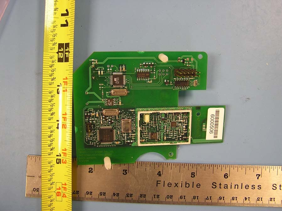
KCHMXU530T
Aug 22, 2006Radio Transceiver for Electric Meter
Equipment Class
DTS - Digital Transmission System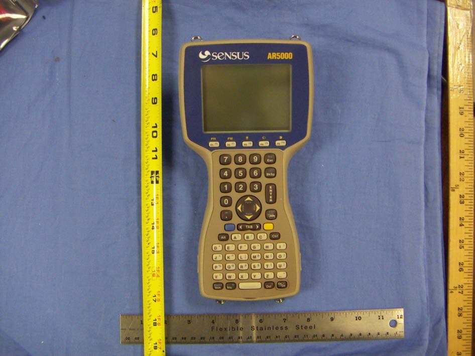
KCHAR5002
Jun 13, 2006Utility Meter RF Transceiver
Equipment Class
DXT - Part 15 Low Power Transceiver, Rx Verified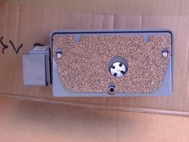
KCHGS0003
Jan 19, 2005AUTOMATIC GAS METER TRANSMITTER
Equipment Class
DTS - Digital Transmission System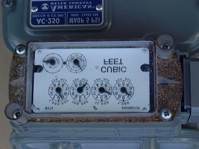
KCHGS0001
Jan 19, 2005AUTOMATIC GAS METER TRANSMITTER
Equipment Class
DTS - Digital Transmission System