KCHMXU530TRadio Transceiver for Electric Meter
Sensus Metering Systems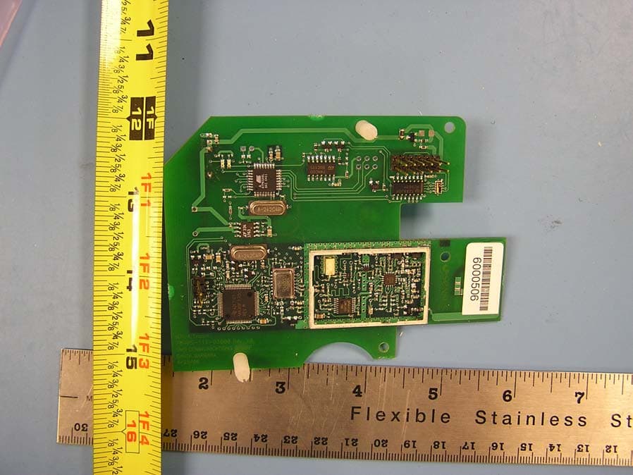
Click to zoom
Application Details
- Equipment Class
- DTS - Digital Transmission System
- Date of Grant
- Aug 22, 2006
- Application Purpose
- Original Equipment
- Date of Application
- Aug 22, 2006
- Equipment Note
- Radio Transceiver for Electric Meter
- Frequency Range
- 904.60000000 - 925.40000000
- Company
- Sensus Metering Systems
- Country
- United States
Documents & Files
Document Text
Text extracted from the exhibit documents filed with the FCC. Open a document above to read the original.
Users Manual
Technical Manual iCon APX Advanced Functionality Meter TM-iX0A-0805 1.0 Technical Manual for the iCon APX Advanced Functionality Meter TM-iX0A-0805 1.0 TM-iX0A-0805 1.0 Information in the document is subject to change without notice and does not represent a commitment on the part of Sensus Metering Systems-North America Inc. The electricity meter described in this document is furnished under a license agreement or nondisclosure agreement. This document may be used or copied only in accordance with the terms of those agreements. No part of this document may be reproduced, stored in a retrieval system, or transmitted in any form or any means electronic or mechanical, including printing and recording for any purpose other than the purchaser’s personal use without the written permission of Sensus Metering Systems-North America, Inc. THE INFORMATION CONTAINED IN THIS MANUAL IS PRESENTED "AS IS", WITHOUT WARRANTY. IN NO EVENT SHALL SENSUS METERING SYSTEMS-NORTH AMERICA INC. BE LIABLE FOR ANY DIRECT, INDIRECT, SPECIAL, INCIDENTAL OR CONSEQUENTIAL DAMAGES ARISING OUT OF ANY USE OF SUCH INFORMATION, INCLUDING, WITHOUT LIMITATION, ANY OMISSIONS OR TECHNICAL OR EDITORIAL ERRORS IN THE TEXT. © Copyright 2005, Sensus Metering Systems-North America Inc. All Rights Reserved. iCon APX™, iConFig™ and associated logos are trademarks of Sensus Metering Systems-North America Inc. and its subsidiaries and affiliates. All other brand names may be trademarks of their respective owners. Technical Manual iCon APX Advanced Functionality Meter Version 1.0, September, 2005 Document Number: TM-iX0A-0805 Sensus Metering Systems 1501 Ardmore Boulevard, Suite 600 Pittsburgh, PA 15221 USA 1-800-METER-IT (638-3748) 1 800-888-2403 (fax) www.sensus.com Table of Contents i Table of Contents CHAPTER 1 Introduction Overview ................................................................................................................................................ 1-1 Purpose ............................................................................................................................................... 1-2 Safety ................................................................................................................................................. 1-2 Manual Conventions .............................................................................................................................. 1-2 Additional Information Sources ......................................................................................................... 1-2 Notational Conventions...................................................................................................................... 1-3 Hexadecimal Values....................................................................................................................... 1-3 Ranges ............................................................................................................................................ 1-3 Register Notation and Usage.......................................................................................................... 1-3 Applicable Standards ......................................................................................................................... 1-4 CHAPTER 2 Meter Overview iCon APX Meter .................................................................................................................................... 2-1 Accuracy ............................................................................................................................................ 2-1 Reliability ........................................................................................................................................... 2-1 Expandability ..................................................................................................................................... 2-1 Tamper Resistance ............................................................................................................................. 2-1 System Architecture ............................................................................................................................... 2-2 Hardware ............................................................................................................................................ 2-3 Meter Base Assembly .................................................................................................................... 2-3 Register Cover Assembly............................................................................................................... 2-7 Meter Cover ................................................................................................................................. 2-14 Metering Capabilities ........................................................................................................................... 2-15 Display Lists .................................................................................................................................... 2-16 Normal Display List ..................................................................................................................... 2-16 Alternate Display List .................................................................................................................. 2-16 Test Display List .......................................................................................................................... 2-16 Diagnostic Display List................................................................................................................ 2-17 Security ............................................................................................................................................ 2-18 CHAPTER 3 Operation Hardware Setup ........................................................................................................................…
Text truncated - open the document above for the full version.
Attestation Statements
tel: 650-726-1263 fax: 650-726-1252 [email protected] Thomas N. Cokenias EMC &Radio Approvals Test & Consulting Services for Commercial, Military, International Compliance P.O. Box 1086 El Granada, CA 94018 email: [email protected] ADDENDUM TO TEST REPORT RE: RF EXPOSURE Applicant: Sensus Metering Systems Inc. FCC ID: KCHMXU530T The EUT is a utility meter transmitter that transmits customer usage data when it is interrogated by a utility company truck-mounted transmitter. The EUT, when interrogated, will respond with a 72msec burst of data. These meters typically transmit 1-5 times per month, at most once per day. The time- averaged RF exposure levels are therefore extremely low. Per FCC’s Knowledge Data Per FCC’s Knowledge Data Base inquiry number 848176, for very low duty cycle utility meters, grant notes and user manual notes referencing MPE limits are not required.
Cover Letter(s)
tel: 650-726-1263 fax: 650-726-1252 [email protected] Thomas N. Cokenias EMC &Radio Approvals Test & Consulting Services for Commercial, Military, International Compliance P.O. Box 1086 El Granada, CA 94018 Compliance Certification Services 25 July 2006 561F Monterey Road Morgan Hill, CA 95037 Attention: Application Examiner Re: Request for confidentiality per Sections 0.457 and 0.459 of FCC Rules Applicant: Sensus Metering Systems FCC ID: KCHMXU530T 900MHz DTS RF Module To whom it may concern, Request is hereby submitted, on behalf of my client Sensus Metering Systems to withhold from public review certain portions of the application for equipment certification for the referenced FCC identifier. In particular, the following sections of the application and report are requested to be kept confidential: Block Diagrams Schematic Operational Description Rationale for request for confidentiality: Sensus has invested considerable time and materials in research and development to produce the referenced product. Disclosure of the confidential portions of this application to competitors would give them competitive advantage in developing similar products. If you have questions or need further information, please contact the undersigned. Sincerely, THOMAS N. COKENIAS EMC Consultant Agent for Sensus Metering Systems
Cover Letter(s)
1 Helen Zhao Subject: FW: Sensus Metering Systems, FCC ID: KCHMXU530T, Assessment NO.: AN06T5973, Notice#1 KCHMXU530T Report REV2.pdf KCH530T User Manual Waiver.pdf.. 530T conf.pdf From: Thomas Cokenias Sent: Wednesday, August 16, 2006 11:33 AM To: Helen Zhao Subject: Re: Sensus Metering Systems, FCC ID: KCHMXU530T, Assessment NO.: AN06T5973, Notice#1 Hi Helen, Answers follow questions. best regards Tom > -----Original Message----- > Sent: Friday, July 21, 2006 4:31 PM > Subject: Sensus Metering Systems, FCC ID: KCHMXU530T, Assessment NO.: > AN06T5973, Notice#1 > Question #1: Please submit user manual or OEM installation manual. ANS 1 The OEM installation manual is attached > > Question #2: The confidentiality letter does not refer to FCC rule part 0.457 or 0.459, please modify request for confidentiality letter. ANS 2 Corrected confidentiality letter is attached. > > Question #3: Please provide fundamental field strength value at > low, middle, high channel. Please note fundamental is in 902-928 > MHz band, below 1GHz, so the measurement should be made with a > CISPR quasi-peak detector, hence, harmonic limit should be Peak: > fundamental - 20dB, average: fundamenal - 40dB. ANS 3 All harmonic and spurious emissions were well below limits for restricted bands or -20 dBc. Refer to page 5 of revised test report. > > Question #4: Please provide vertical plots and test data for > radiated emission test from 30-902MHz, and 928-1000MHz. ANS 4 Revised report attached. > > Question #5: The test report shows EMC test receiver was past due > during the test. Please update the report. ANS 5 Revised report attached > > Question #6: Please privide test setup diagram or description, if 2 > any support equipment was used, please list in the report. Please > explain how to tune the device to low, middle, high channel during > the test. ANS 6 Refer to revised report page 3 for test set-up. Laptop is connected to EUT to change operating frequency. > > Best Regards, > Helen Zhao > > The items indicated above must be submitted before processing can > continue on the above referenced application. Failure to provide > the requested information within 30 days of the original e-mail > date may result in application dismissal and forfeiture of the > filing fee. Also, please note that partial responses increase > processing time and should not be submitted. Any questions about > the content of this correspondence should be directed to the e-mail > address listed below the name of the sender.
External Photos
Product Photographs Sensus Metering Systems FCC ID: KCHMXU530T IC: 2220A-MXU530T
ID Label/Location Info
PROPOSED FCC ID LABEL FOR HOST DEVICE THIS DEVICE CONTAINS FCC ID: KCHMXU530T
Internal Photos
Product Photographs Sensus Metering Systems FCC ID: KCHMXU530T IC: 2220A-MXU530T
Test Report
Sensus Metering Systems FCC ID: KCHMXU530T Report No. 06PR042FCCREP REV 1.1 Sensus 530-T Electric Meter Transceiver Module 1 of 43 900MHz DTS EMISSIONS TEST REPORT FOR A LOW POWER TRANSMITTER I. GENERAL INFORMATION Requirement: Federal Communications Commission Test Requirements: 15.205, 15.207, 15.209, 15.247 Applicant: Sensus Metering Systems FCC ID: KCHMXU530T Model No.: 530-T II. DESCRIPTION OF EQUIPMENT UNDER TEST (EUT) The Sensus Model 530-T MXU (Meter Transceiver Unit) FCC ID: KCHMXU530T, IC: 2220AMXU530T is a Radio Frequency transceiver unit operating under CFR47 Part 15 of the FCC rules. The Model 530-T incorporates a part 15.247 Direct Sequence Spread Spectrum Transmitter operating in the 902 to 928 MHz ISM band, and a Part 15 AM Receiver operating in the 952 or 956 MHz MAS bands. The MXU uses spread spectrum techniques for remote electric meter reading. Transmitter Specification TX Power 23.58 dBm max. Frequency of operation 904.6-925.4 MHz Data Rate and Modulation DSSS RF Data Rate 15.625 Kb/s RF Chip Rate 1 Mb/s (Spreading Sequence = 64 chips/bit) Typical application 50msec burst/week 6 dB bandwidth 1.16 MHz Power source 3.6 V lithium thionyl chloride battery Radio firmware MXU4 GP-TC v0.0.4 (MXU 4.13.7) Test software name GetApp.exe Test Software (MXU5T100) III. TEST DATES AND TEST LOCATION Testing was performed 16-21 June 2006. All tests were performed at: Compliance Certification Services 561F Monterey Road Morgan Hill, CA 95037 Sensus Metering Systems FCC ID: KCHMXU530T Report No. 06PR042FCCREP REV 1.1 Sensus 530-T Electric Meter Transceiver Module 2 of 43 900MHz DTS IV. REVISION INFORMATION AND ATTESTATION OF RESULTS Report No: 06PR042FCCREP REV No. Description Revised By: Date 1.0 Original T. Cokenias 27 June 2006 1.1 Per TCB comments T. Cokenias 24 July 2006 Test Requirement: FCC Part 15 Manufacturer: Sensus Metering Systems FCC ID: KCHMXU530T Brand name: Sensus Metering Systems Model Nos.: 530T IC: 2220A-MXU530T FCC ID: KCHMXU530T meets all FCC requirements for a device of this type. THOMAS N. COKENIAS 24 July 2006 EMC and Radio Regulatory Consultant Agent for Sensus Metering Systems 15.203 Antenna connector requirement The antenna is permanently attached to the product. For antenna conducted tests, a unit was modified by disconnecting the printed circuit antenna and replacing it with a 50 ohm coaxial cable connection terminated at one end with an SMA connector. Antenna description The meter transceiver uses a printed circuit folded dipole antenna: Antenna description Gain printed ckt antenna 2.2 dBi Sensus Metering Systems FCC ID: KCHMXU530T Report No. 06PR042FCCREP REV 1.1 Sensus 530-T Electric Meter Transceiver Module 3 of 43 900MHz DTS TEST PROCEDURES All tests were performed in accordance with the applicable procedures called out in the following documents, unless otherwise noted: 1) ANSI C63.4 – 2003, American National Standard for Methods of Measurement of Radio-Noise Emissions from Low-Voltage Electrical and Electronic Equipment in the Range of 9 kHz to 40 GHz 2) FCC Public Notice 97-114, Guidance on Measurements for Direct Sequence Spread Spectrum Systems For each measurement reported below, EUT was set to produce maximum output power: Channel Frequency, MHz Peak Output Power, dBm LOW 904.6 23.58 MID 915.0 21.83 HIGH 925.4 21.94 TEST SET-UP Radiated emissions Antenna port conducted emissions EUT w/integral antenna Battery pack Laptop for setting frequency Laptop removed during test EUT w/coax matching ant. impedance Battery pack Laptop for setting frequency Spectrum Analyzer Laptop removed during test Sensus Metering Systems FCC ID: KCHMXU530T Report No. 06PR042FCCREP REV 1.1 Sensus 530-T Electric Meter Transceiver Module 4 of 43 900MHz DTS TEST RESULTS Radiated Emissions Test Requirement: 15.205, 15.247 Out of Band Measurements Test Requirement: 15.247 Radiated Test Set-up, 1-26 GHz 1-4m 3m EUT preamplifier Fig. 1 Test Procedures Radiated emissions generated by the transmitter portion of the EUT were measured. 1. The EUT was placed on a wooden table resting on a turntable on the test site. The search antenna was placed 3m from the EUT. The EUT antenna was positioned in the XY plane (“X-hat”), the first of three test positions. 2. The turntable was slowly rotated to locate the direction of maximum emission at each emission falling in the restricted bands of 15.205. 3. Radiated emissions were investigated for a LOW channel, a MID channel, and HIGH channel. Emissions were investigated to the 10 th harmonic. Sensus Metering Systems FCC ID: KCHMXU530T Report No. 06PR042FCCREP REV 1.1 Sensus 530-T Electric Meter Transceiver Module 5 of 43 900MHz DTS 4. Once maximum direction was determined, the search antenna was raised and lowered in both vertical and horizontal polarizations. The maximum readings so obtained are recorded in the data listed below. 5. Steps 2 - 5 were repeated for YZ (“Y-hat”) and XZ (“Z-hat”) orientation of the EUT. Test Results: Worst-case results are presented (Y-hat position). Refer to data sheets below. Restricted band emissions meet 54 dBuV/m. Other undesired emissions from the transmitter meet the -20 dBc requirement in 15.247(c), as follows: Maximum output power in 100kHz BW = 18.77 dBm (refer to spurious emission plots below) Calculated fundamental frequency field strength at 3m: 95.24 + P dBm + G, dBi = 95.24dB + 18.77dBm + 2.2dBi = 116.2 dBuV/m 116.2 dBuV/m – 20 dB = 96.2 dBuV/m limit for non-restricted band emissions outside 902-928 MHz operating frequency band. Non-restricted band emissions measured at more than 20 dB below limit, refer to data sheets below. Sensus Metering Systems FCC ID: KCHMXU530T Report No. 06PR042FCCREP REV 1.1 Sensus 530-T Electric Meter Transceiver Module 6 of 43 900MHz DTS FCC Radiated Emissions Limits Section 15.205 Restricted bands of operation. (a) Except as shown in paragraph (d) of this section, only spurious emissions are permitted in any of the frequency bands listed below: MHz MHz MHz GHz 0.090 - 0.11…
Text truncated - open the document above for the full version.
Test Setup Photos
Test Set-up Photographs Sensus Metering Systems FCC ID: KCHMXU530T IC: 2220A-MXU530T Antenna Port Conducted Radiated Emissions AC Line Conducted
Contact Information
Applicant
Richard Daniel(Director, Engineering NPI and Project Management)
Test Firm
Compliance Certification ServicesBarbara Judge
Technical Specifications
| # | Rule Parts | Frequency Range | Power Output |
|---|---|---|---|
| 1 | 15C | 904.6 MHz - 925.4 MHz | 228.00 mW |
Other Applications from Sensus Metering Systems
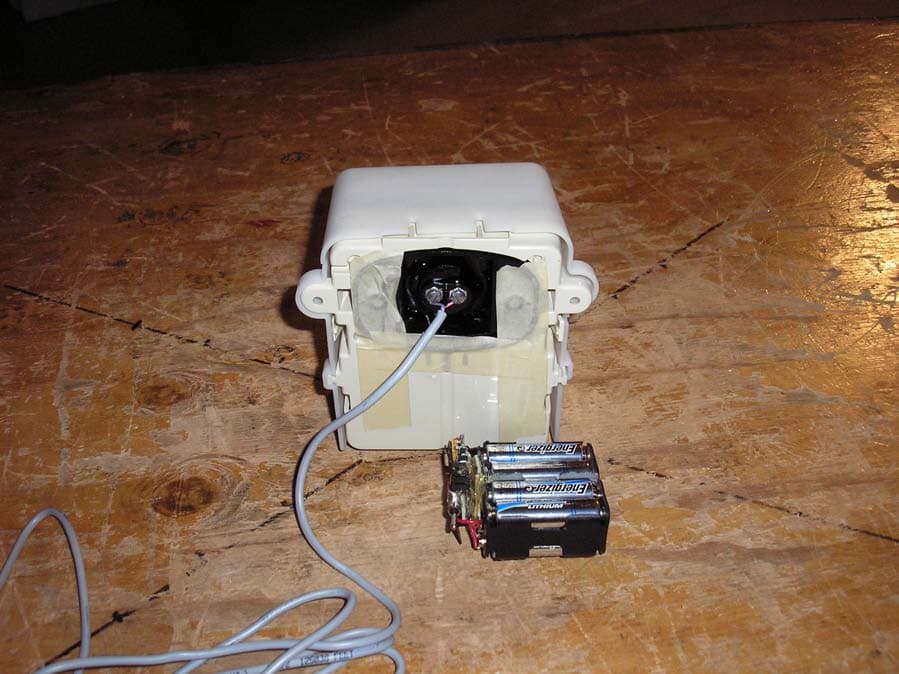
KCH510R2
Nov 13, 2006Utility Meter Transceiver
Equipment Class
DTS - Digital Transmission System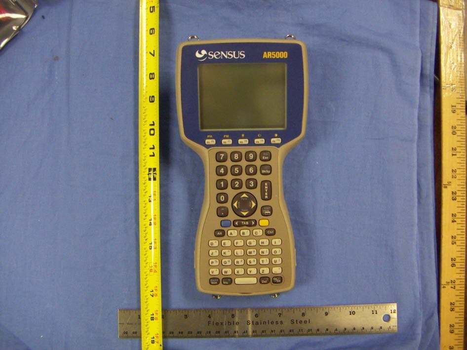
KCHAR5002
Jun 13, 2006Utility Meter RF Transceiver
Equipment Class
DXT - Part 15 Low Power Transceiver, Rx Verified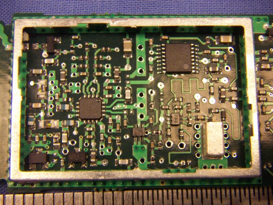
KCH520R
Jun 28, 2005900MHz DTS RF Module
Equipment Class
DTS - Digital Transmission System
KCHGS0003
Jan 19, 2005AUTOMATIC GAS METER TRANSMITTER
Equipment Class
DTS - Digital Transmission System
KCHGS0001
Jan 19, 2005AUTOMATIC GAS METER TRANSMITTER
Equipment Class
DTS - Digital Transmission System