KFY-WA4270IEEE 802.11g Wireless Cardbus Network Adapter
Runtop Inc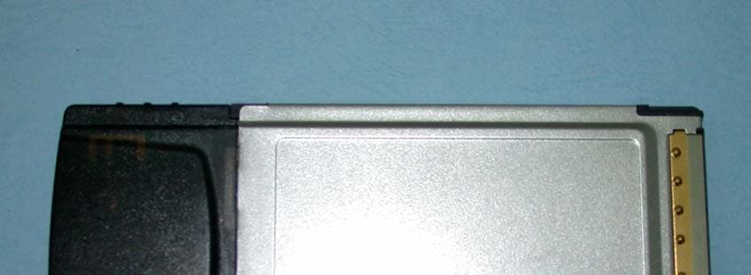
Click to zoom
Application Details
- Equipment Class
- DTS - Digital Transmission System
- Date of Grant
- Apr 04, 2004
- Application Purpose
- Original Equipment
- Date of Application
- Apr 04, 2004
- Equipment Note
- IEEE 802.11g Wireless Cardbus Network Adapter
- Frequency Range
- 2412.00000000 - 2462.00000000
- Company
- Runtop Inc
- Country
- Taiwan
Documents & Files
Document Text
Text extracted from the exhibit documents filed with the FCC. Open a document above to read the original.
Users Manual
The information in this guide may change without notice. The manufacturer assumes no responsibility for any errors that may appear in this guide. Ethernet is a trademark of XEROX Corporation. Microsoft, Windows and Windows logo are trademarks of Microsoft Corporation. Copyright 2004, Manufacturer. All right reserved. No Part of the contents of this guide maybe transmitted or reproduced in any form or by any means without the written permission of manufacturer. Printed in Taiwan. The revision date for this guide is Apr. 2nd, 2004 FCC Statement This equipment has been tested and found to comply with the limits for a Class B digital device, pursuant to Part 15 of the FCC Rules. These limits are designed to provide reasonable protection against harmful interference in a residential installation. This equipment generates, uses and can radiate radio frequency energy and, if not installed and used in accordance with the instructions, may cause harmful interference to radio communications. Operation of this equipment in a residential area is likely to cause interference in which case the user, at his or her own expense will be required to take whatever measures may be required to correct the interference. However, there is no guarantee that interference will not occur in a particular installation. If this equipment does cause harmful interference to radio or television reception, which can be determined by turning the equipment off and on, the user is encouraged to try to correct the interference by one of the following measures: - Reorient or relocate the receiving antenna. - Increase the separation between the equipment and receiver. - Connect the equipment into an outlet on a circuit different from that to which the receiver is connected. - Consult the dealer or an experienced radio/TV technician for help. This device complies with Part 15 of the FCC Rules. Operation is subject to the following two conditions: (1) This device may not cause harmful interference, and (2) this device must accept any interference received, including interference that may cause undesired operation. FCC Caution: Any changes or modifications not expressly approved by the party responsible for compliance could void the user's authority to operate this equipment. IMPORTANT NOTE: FCC Radiation Exposure Statement: This equipment complies with FCC radiation exposure limits set forth for an uncontrolled environment. End users must follow the specific operating instructions for satisfying RF exposure compliance. This transmitter must not be co-located or operating in conjunction with any other antenna or transmitter. CE Mark Warning This is a Class B product. In a domestic environment, this product may cause radio interference in which case the user may be required to take adequate measures. 1. Introduction Thank you for purchasing our 802.11g Wireless Cardbus/PCI/PCI/PCI Network Adapter. This user guide is aimed at easy installation procedures of this device. Before your installation to your computer, please read the following procedures carefully. This is a Wireless Cardbus/PCI Network Adapter, which provides you the most reliable and fastest way to access a wireless network. This product can be operated in Ad-Hoc (peer-to-peer mode or without an Access Point) and infrastructure (with an Access Point) network configuration. 1.1 Package Contents The package contains the following: One Wireless Cardbus/PCI Network Adapter One Wireless Cardbus/PCI Network Adapter Driver & Utility plus User’s Guide CD-ROM 2. Installation 2.1 Getting Started You may complete the following steps to install your Wireless Cardbus/PCI Network Adapter when you have all the information mentioned above on hand. First, you have to install software (Utility) and then insert the Wireless Cardbus/PCI Network Adapter to your system, and finally set the network properties to accommodate resource sharing the select the type of wireless network that you wish to install. Note: In the Windows XP system, there are two ways to configure the utility. If you wish to use the Windows XP built-in utility, click StartÆSettingsÆControl PanelÆAdministrative ToolsÆServicesÆ Wireless Zero Configuration. Click with right key of mouse, and then select Start. The Windows XP built-in utility will lead you to configure. If you wish to use the adapter built-in utility, follow the same step, and select Stop. Step 1. Insert the Wireless Cardbus/PCI Network Adapter Driver & Utility CD-ROM into your CD-ROM drive. The InstallShield Wizard will run for preparing to install. Figure 2.1 Step 2. The Wireless Cardbus/PCI Network Adapter Driver and Utility – Install Shield Wizard will appear. Click Next to proceed. Figure 2.2 Step 3. The License Agreement will appear. Click on I accept the terms in the license agreement, and Next to proceed. Figure 2.3 Step 4. Now the Wizard is ready to install the program. Click Install to perform this step. Figure 2.4 Step 5. It might take a few minutes to run the installation. Figure 2.5 Step 6. Windows will notify you that the driver has not passed the Windows Logo testing. Because the network adapter has been tested to work with Windows XP, please click Continue Anyway to proceed. Figure 2.6 Step 7. When the InstallShield Wizard has successfully installed Wireless Cardbus/PCI Network Adapter Driver and Utility, click Finish to confirm. Figure 2.7 Step 8. Insert / attach Wireless Cardbus/PCI Network Adapter Network Adapter to your system. Windows will display the Welcome to the Found New Hardware Wizard box as Figure 2.8. Select Install the software automatically [Recommended], and then click Next to continue. Figure 2.8 Step 9. The searching box will appear. Please wait for the next screen. Figure 2.9 Step 10. Windows will notify you that the driver has not passed the Windows Logo testing. Because the network adapter has been tested to work with Windows XP, please choose Continue Anyway. Figure 2.10 Step 11. The Completing the Found New Hardware…
Text truncated - open the document above for the full version.
External Photos
Page 1 CONSTRUCTION PHOTOS OF EUT Page 2 Page 3
Internal Photos
Page 4 Page 5 Page 6
Operational Description
FCC ID: KFY-WA4270 Report No.930324L02 Operational Description This device is a IEEE 802.11g Wireless Cardbus Network Adapter which operates in the 2.4GHz frequency spectrum with throughput of up to 54Mbps which OFDM technique will be applied. If the signal to noise radio is too poor which could not support 54Mbps, the 11Mbps data rate with CCK technique will be applied. The transmitter of the EUT is powered by host equipment. The antenna is Printed antenna without any connector. The other instruction, please have a look at the users manual.
RF Exposure Info
FCC ID: KFY-WA4270 Report No.: SA930324L021Issued: 29 March, 2004 SAR TEST REPORT REPORT NO.: SA930324L02 MODEL NO.: WA4270 RECEIVED: 24 March, 2004 TESTED: 26 March, 2004 APPLICANT: Runtop Inc. ADDRESS: 1, Lane 21, Hsin Hua Rd., Kueishan Industrial Park, Taoyuan City, Taiwan. ISSUED BY: Advance Data Technology Corporation LAB LOCATION: 47 14th Lin, Chiapau Tsun, Linko, Taipei, Taiwan, R.O.C. This test report consists of 32 pages in total except Appendix. It may be duplicated completely for legal use with the approval of the applicant. It should not be reproduced except in full, without the written approval of our laboratory. The client should not use it to claim product endorsement by CNLA or any government agencies. The test results in the report only apply to the tested sample. 0528 ILAC MRA FCC ID: KFY-WA4270 Report No.: SA930324L022Issued: 29 March, 2004 Table of Contents 1.CERTIFICATION .........................................................................................................3 2.GENERAL INFORMATION..........................................................................................4 2.1 GENERAL DESCRIPTION OF EUT............................................................................4 2.2 GENERAL DESCRIPTION OF APPLIED STANDARDS .............................................5 2.3 GENERAL INOFRMATION OF THE SAR SYSTEM ...................................................5 2.4 GENERAL DESCRIPTION OF THE SPATIAL PEAK SAR EVALUATION .................9 3.DESCRIPTION OF TEST MODES AND CONFIGURATIONS ..................................13 4.DESCRIPTION OF SUPPORT UNITS ......................................................................14 5.TEST RESULTS ........................................................................................................15 5.1 TEST PROCEDURES ...............................................................................................15 5.2 MEASURED SAR RESULT .......................................................................................16 5.3 SAR LIMITS...............................................................................................................18 5.4 RECIPES FOR TISSUE SIMULATING LIQUIDS ......................................................19 5.5 TEST EQUIPMENT FOR TISSUE PROPERTY ........................................................21 6.SYSTEM VALIDATION ..............................................................................................22 6.1 TEST EQUIPMENT ...................................................................................................22 6.2 TEST PROCEDURE .................................................................................................22 6.3 VALIDATION RESULT...............................................................................................24 6.4 SYSTEM VALIDATION UNCERTAINTIES ................................................................25 7.MEASUREMENT SAR PROCEDURE UNCERTAINTIES.........................................26 7.1 PROBE CALIBRATION UNCERTAINTY ...................................................................26 7.2 ISOTROPY UNCERTAINTY......................................................................................26 7.3 BOUNDARY EFFECT UNCERTAINTY .....................................................................27 7.4 PROBE LINEARITY UNCERTAINTY ........................................................................27 7.5 READOUT ELECTRONICS UNCERTAINTY ............................................................27 7.6 RESPONSE TIME UNCERTAINTY...........................................................................28 7.7 INTEGRATION TIME UNCERTAINTY ......................................................................29 7.8 PROBE POSITIONER MECHANICAL TOLERANCE................................................29 7.9 PROBE POSITIONING .............................................................................................30 7.10 PHANTOM UNCERTAINTY ......................................................................................30 7.11 DASY4 UNCERTAINTY BUDGET.............................................................................31 8.INFORMATION ON THE TESTING LABORATORIES ..............................................32 APPENDIX A: TEST CONFIGURATIONS AND TEST DATA APPENDIX B: ADT SAR MEASUREMENT SYSTEM APPENDIX C: PHOTOGRAPHS OF SYSTEM VALIDATION APPENDIX D: SYSTEM CERTIFICATE & CALIBRATION FCC ID: KFY-WA4270 Report No.: SA930324L023Issued: 29 March, 2004 1. CERTIFICATION PRODUCT : IEEE 802.11g Wireless Cardbus Network Adapter MODEL NO. : WA4270 BRAND NAME : Runtop APPLICANT : Runtop Inc. TEST ITEM : R & D SAMPLE STANDARDS : FCC Part 2 (Section 2.1093), FCC OET Bulletin 65, Supplement C (01-01), RSS-102 We, Advance Data Technology Corporation, hereby certify that one sample of the designation has been tested in our facility on 26 March, 2004. The test record, data evaluation and Equipment Under Test (EUT) configurations represented herein are true and accurate, and it was tested according to the standards listed above. This device was found to be in compliance with the Specific Absorption Rate (SAR) requirement specified in FCC part 2.1093 under General Population / Uncontrolled Exposure condition. FCC ID: KFY-WA4270 Report No.: SA930324L024Issued: 29 March, 2004 2. GENERAL INFORMATION 2.1 GENERAL DESCRIPTION OF EUT PRODUCT IEEE 802.11g Wireless Cardbus Network Adapter MODEL NO. WA4270 POWER SUPPLY 3.3Vdc powered by host equipment CLASSIFICATION Portable device, production unit MODULATION TYPE BPSK, QPSK, CCK, 16QAM, 64QAM RADIO TECHNOLOGY DSSS, OFDM TRANSFER RATE 54/48/36/24/18/12/11/9/6/5.5/2/1Mbps FREQUENCY RANGE 2412MHz ~ 2462MHz NUMBER OF CHANNEL 11 MAXIMUN CONDUCTED OUTPUT POWER (FOR CCK) 17.50dBm MAXIMUN CONDUCTED OUTPUT POWER (FOR OFDM) 16.20dBm ANTENNA TYPE PCB antenna with 1dBi gain AVERAGE SAR(1g) (FOR CCK) 1.020W/kg AVERAGE SAR(1g) (FOR OFDM) 0.301W/kg DATA CABLE NA I/O PORTS Card…
Text truncated - open the document above for the full version.
Test Report
FCC ID: KFY-WA4270 Report No.: RF930324L021Issued: Mar. 31, 2004 FCC TEST REPORT REPORT NO.: RF930324L02 MODEL NO.: WA4270 RECEIVED: Mar. 6, 2004 TESTED: Mar. 6, 2004 ~ Mar. 27, 2004 APPLICANT: Runtop Inc ADDRESS: 7F, #18, Lane 33, Chai-An St., Hsintien, Taipei Taiwan, R.O.C. ISSUED BY: Advance Data Technology Corporation LAB LOCATION: 47 14th Lin, Chiapau Tsun, Linko, Taipei, Taiwan, R.O.C. This test report consists of 68 pages in total. It may be duplicated completely for legal use with the approval of the applicant. It should not be reproduced except in full, without the written approval of our laboratory. The client should not use it to claim product endorsement by CNLA or any government agencies. The test results in the report only apply to the tested sample. 0528 ILAC MRA FCC ID: KFY-WA4270 Report No.: RF930324L022Issued: Mar. 31, 2004 Table of Contents 1CERTIFICATION.............................................................................................. 4 2SUMMARY OF TEST RESULTS ..................................................................... 5 3GENERAL INFORMATION .............................................................................. 6 3.1GENERAL DESCRIPTION OF EUT ................................................................ 6 3.2DESCRIPTION OF TEST MODES .................................................................. 7 3.3GENERAL DESCRIPTION OF APPLIED STANDARDS ................................. 7 3.4DESCRIPTION OF SUPPORT UNITS ............................................................ 8 3.5 CONFIGURATION OF SYSTEM UNDER TEST.............................................. 9 4TEST TYPES AND RESULTS ....................................................................... 10 4.1CONDUCTED EMISSION MEASUREMENT................................................. 10 4.1.1 LIMITS OF CONDUCTED EMISSION MEASUREMENT .............................. 10 4.1.2 TEST INSTRUMENTS ................................................................................... 10 4.1.3 TEST PROCEDURES ....................................................................................11 4.1.4 DEVIATION FROM TEST STANDARD ...........................................................11 4.1.5 TEST SETUP................................................................................................. 12 4.1.6 EUT OPERATING CONDITIONS .................................................................. 12 4.1.7 TEST RESULTS ............................................................................................ 13 4.2RADIATED EMISSION MEASUREMENT ..................................................... 19 4.2.1 LIMITS OF RADIATED EMISSION MEASUREMENT ................................... 19 4.2.2 TEST INSTRUMENTS ................................................................................... 20 4.2.3 TEST PROCEDURES ................................................................................... 21 4.2.4 DEVIATION FROM TEST STANDARD .......................................................... 21 4.2.5 TEST SETUP................................................................................................. 22 4.2.6 EUT OPERATING CONDITIONS .................................................................. 22 4.2.7 TEST RESULTS ............................................................................................ 23 4.2.8 TEST RESULTS (A)....................................................................................... 25 4.2.9 TEST RESULTS (B)....................................................................................... 28 4.36dB BANDWIDTH MEASUREMENT ............................................................. 31 4.3.1 LIMITS OF 6dB BANDWIDTH MEASUREMENT........................................... 31 4.3.2 TEST INSTRUMENTS ................................................................................... 31 4.3.3 TEST PROCEDURE ...................................................................................... 32 4.3.4 DEVIATION FROM TEST STANDARD .......................................................... 32 4.3.5 TEST SETUP................................................................................................. 32 4.3.6 EUT OPERATING CONDITIONS .................................................................. 32 4.3.7 TEST RESULTS (A)....................................................................................... 33 FCC ID: KFY-WA4270 Report No.: RF930324L023Issued: Mar. 31, 2004 4.3.8 TEST RESULTS (B) ...................................................................................... 37 4.4MAXIMUM PEAK OUTPUT POWER............................................................. 41 4.4.1 LIMITS OF MAXIMUM PEAK OUTPUT POWER MEASUREMENT.............. 41 4.4.2 TEST INSTRUMENTS ................................................................................... 41 4.4.3 TEST PROCEDURES ................................................................................... 42 4.4.4 DEVIATION FROM TEST STANDARD .......................................................... 42 4.4.5 TEST SETUP................................................................................................. 42 4.4.6 EUT OPERATING CONDITIONS .................................................................. 42 4.4.7 TEST RESULTS (A)....................................................................................... 43 4.4.8 TEST RESULTS (B)....................................................................................... 43 4.5POWER SPECTRAL DENSITY MEASUREMENT ........................................ 44 4.5.1 LIMITS OF POWER SPECTRAL DENSITY MEASUREMENT ...................... 44 4.5.2 TEST INSTRUMENTS ................................................................................... 44 4.5.3 TEST PROCEDURE ...................................................................................... 45 4.5.4 DEVIATION FROM TEST STANDARD ................................................…
Text truncated - open the document above for the full version.
Test Setup Photos
FCC ID: KFY-WA4270 Report No.: RF930324L0266Issued: Mar. 31, 2004 5 PHOTOGRAPHS OF THE TEST CONFIGURATION CONDUCTED EMISSION TEST FCC ID: KFY-WA4270 Report No.: RF930324L0267Issued: Mar. 31, 2004 RADIATED EMISSION TEST
Contact Information
Applicant
Ryan Ho(Project Manager)
Technical Contact
Advance Data Technology Corp.Ellis Wu
[email protected]+886-3-327-0910
13-1 Lane 19 WenShan 3rd Street · Taoyuan · Taiwan
Test Firm
Advance Data Technology CorporationStephen Chen
Technical Specifications
| # | Rule Parts | Frequency Range | Power Output |
|---|---|---|---|
| 1 | 15C | 2.41 GHz - 2.46 GHz | 56.00 mW |
Other Applications from Runtop Inc

KFY-WA4020
Sep 06, 2004802.11g USB Adapter
Equipment Class
DTS - Digital Transmission System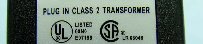
KFY-WR4457
Aug 07, 2004802.11g WLAN Router
Equipment Class
DTS - Digital Transmission System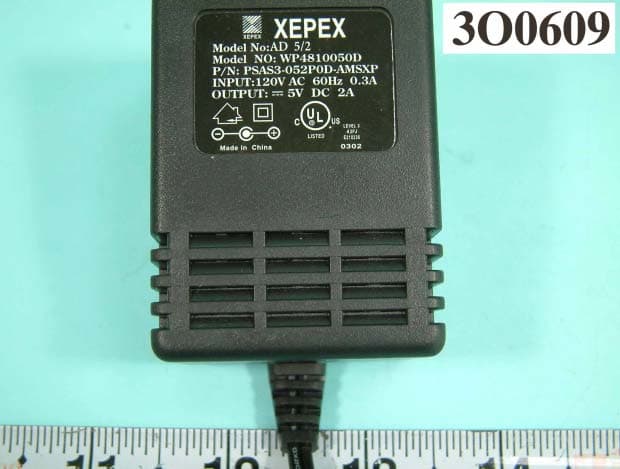
KFY-WR1230
Jan 05, 2004802.11b WIRELESS ROUTER
Equipment Class
DTS - Digital Transmission SystemKFYE350
Jan 07, 1997JBP - Part 15 Class B Computing Device Peripheral
Equipment Class
JBP - Part 15 Class B Computing Device PeripheralKFYE450AT
May 07, 1996PCMCIA Lan Card
Equipment Class
JBP - Part 15 Class B Computing Device Peripheral