KHH14RCReceiver
TRW Automotive Electronics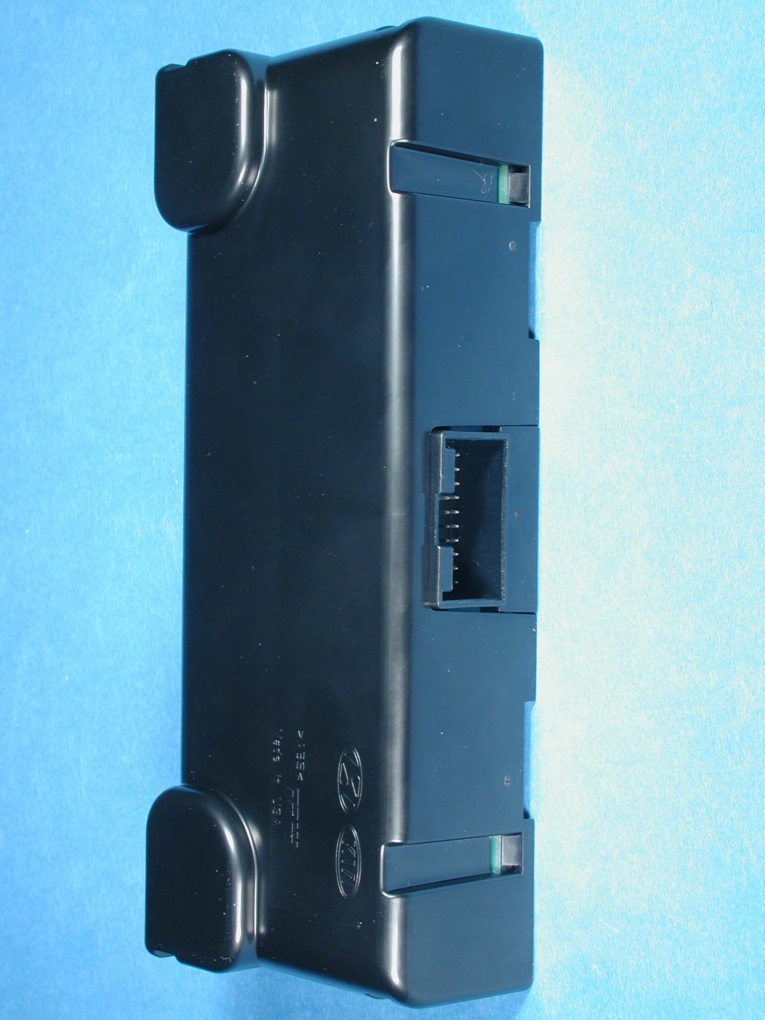
Click to zoom
Application Details
- Equipment Class
- CYY - Communications Receiver used w/Pt 15 Transmitter
- Date of Grant
- Jul 05, 2004
- Application Purpose
- Original Equipment
- Date of Application
- Jul 05, 2004
- Equipment Note
- Receiver
- Frequency Range
- 315.00000000 - 315.00000000
- Company
- TRW Automotive Electronics
- Country
- United Kingdom
Documents & Files
Document Text
Text extracted from the exhibit documents filed with the FCC. Open a document above to read the original.
Users Manual
Tyre pressure monitoring users’ guide 1. Introduction Depending on the complexity of the system fitted, the tire pressure monitoring (TPM) system, consists of the following units: • an electronic control unit (ECU) called 14RC • four 29EC initiator units mounted in the wheel arches • and four or five wheel sensors mounted in each of the tires. The system monitors the pressure and temperature within the tires and flags an alarm via an UHF radio link when the tire pressure falls below predetermined limits. The warning display forms part of the dashboard. Two types of system are available, termed high line and low line. In the low line system the 29EC initiators are not fitted and the wheel sensors are factory fitted in active mode. In this application the sensors transmit data routinely every three minutes whether the vehicle is being driven or not. The high line system uses the initiators to transmit a low frequency signal to the wheel sensors – this activates them and this forces them to transmit. The highline system provides a faster update rate from the sensor and can provide an earlier warning of problems. 2. Operation There are no user adjustable controls on the TPM system. All the information is communicated by the dashboard display. The display will have anywhere between two and six lamps depending on the vehicle model, these are TREAD (Transportation Recall Enhancement, Accountability and Documentation act) lamp, diagnostics lamp and four positional indicating lamps (identify actual wheel with the problem). The diagnostics lamp will light if there is a problem with the TPM system, the TREAD lamp typically comes on when any tire is 25% under inflated. When the TREAD lamp comes on, the user is expected to rectify the problem when it is safe to do so. TRW, model 14RC
External Photos
Page: 1/4 Photographs module Photograph 1: Highline receiver 14RC, top view Page: 2/4 Photographs module Photograph 2: Highline receiver 14RC, bottom view Page: 3/4 Photographs module Photograph 5: Lowline receiver 14RC, top view Page: 4/4 Photographs module Photograph 6: Lowline receiver 14RC, bottom view
Internal Photos
Page: 1/4 Photographs module Photograph 3: Highline receiver 14RC, PCB top view Page: 2/4 Photographs module Photograph 4: Highline receiver 14RC, PCB bottom view Page: 3/4 Photographs module Photograph 7: Lowline receiver 14RC, PCB top view Page: 4/4 Photographs module Photograph 8: Lowline receiver 14RC, PCB bottom view
Test Report
EMC Test report 99512030 based on: FCC Part 15, Subpart B, section 15.109 (10-01-03 edition) Receiver TRW 14RC Report number: 99512030 Contents MAIN MODULE............................................................................................................................................ 3 1 I NTRODUCTION ...................................................................................................................................... 3 2 P RODUCT ............................................................................................................................................... 4 3 T EST SCHEDULE ..................................................................................................................................... 4 4 P RODUCT DOCUMENTATION ................................................................................................................... 5 5 O BSERVATIONS AND COMMENTS ........................................................................................................... 5 6 S UMMARY .............................................................................................................................................. 5 7 C ONCLUSIONS ........................................................................................................................................ 6 TEST RESULTS MODULE ......................................................................................................................... 7 1 S UMMARY .............................................................................................................................................. 8 2 E MISSION TESTS ..................................................................................................................................... 9 2.1 Radiated emission ......................................................................................................................9 USED TEST EQUIPMENT MODULE .....................................................................................................13 PHOTOGRAPHS MODULE...................................................................................................................... 18 ADDITIONAL INFORMATION MODULE ............................................................................................ 29 This report comprises of five modules. The total number of pages exclusive of the pages enclosed in the additional information module is: 29 Page: 3 of 29 Main module Report number: 99512030 Main module 1 Introduction This report contains the result of tests performed by: Telefication bv Edisonstraat 12a 6902 PK Zevenaar The Netherlands Telefication complies with the accreditation criteria for test laboratories as laid down in ISO/IEC 17025:1999. The accreditation covers the quality system of the laboratory as well as the specific activities as described in the authorized annex bearing the accreditation number L021 and is granted on 30 November 1990 by the Dutch Council For Accreditation (RvA: Raad voor Accreditatie) . The copyright of this test report is owned by Telefication bv and may not be reproduced except in full without the written approval of Telefication bv. Ordering party: Company name : TRW Automotive Electronics Address : Stratford Road Shirley P.O. Box : B90 4GW City/town : Solihull Country : United Kingdom Date of order : 31 March 2004 Page: 4 of 29 Main module Report number: 99512030 2 Product A sample of the following product was submitted for testing: Product name : Receiver Product category : Unintentional radiators Manufacturer : TRW Automotive Electronics Trade mark : TRW Type designation : 14RC FCC ID : KHH14RC Hardware version : Rev. F Software version : -- Serial number : -- Variant: The 14RC has a variant where some components are not mounted. These components are not involved in the radio frequency part. In this report the normal version is called the High line receiver. The variant is called the Low line receiver. 3 Test schedule Tests were carried out in accordance with the specification detailed in chapter 6 "Summary" of this report. Tests were carried out at the following location: • Telefication, Zevenaar The sample of the product was received on: • 2 April 2004 Tests were carried out on the following dates: • 5 and 6 April 2004 Page: 5 of 29 Main module Report number: 99512030 4 Product documentation For production of this report the following product documentation was used: Description Date Identification Circuit diagram 14RC TPM High line receiver 23/03/04 59307922 (2 sheets) Circuit diagram 14RC TPM Low line receiver 23/03/04 59308085 (2 sheets) 5 Observations and comments This product is a 315 MHz superheterodyne receiver, intended for reception of messages coming from the tire pressure sensors. The receiving antenna is internal. For testing purpose the applicant provided a genric cable harness and diagnostic test box. The diagnostic test box was used in order to verify that the receiver was in its operational mode. 6 Summary The product is intended for use in the following application area: Automotive The sample was tested according to the following specification: FCC Part 15, Subpart B, section 15.109 (10-01-03 edition) Page: 6 of 29 Main module Report number: 99512030 7 Conclusions The sample of the product showed NO NON-COMPLIANCES to the specification stated in chapter 6 of this report. The results of the tests as stated in this report, are exclusively applicable to the product item as identified in this report. Telefication bv does not accept any responsibility for the results stated in this report, with respect to the properties of product items not involved in these tests. All tests are performed by: name : ing. J.C. le Clercq function : Test Engineer signature : Review of test methods and report by: name : ing. P.A. Suringa function : Senior Engineer Radio/EMC signature : The above conclusions have been verified by the following signatory: dat…
Text truncated - open the document above for the full version.
Test Setup Photos
Page: 1/2 Photographs module Photograph 9: Test setup radiated emissions Page: 2/2 Photographs module Photograph 10: Test setup radiated emissions
Contact Information
Applicant
Roger Lee(Approvals Engineer)
01285 657981Fax: 01285 658258
Technical Contact
RFC Technology and NormsRen� Tin�
[email protected]+33 1 3015 7898
5, rue du chant des Oiseaux · Montesson · France
Test Firm
TUV Rheinland Nederland B.V.Ties E. T Koning
Technical Specifications
| # | Rule Parts | Frequency Range | Power Output |
|---|---|---|---|
| 1 | 15B | 315 MHz - 315 MHz | - |
Other Applications from TRW Automotive Electronics
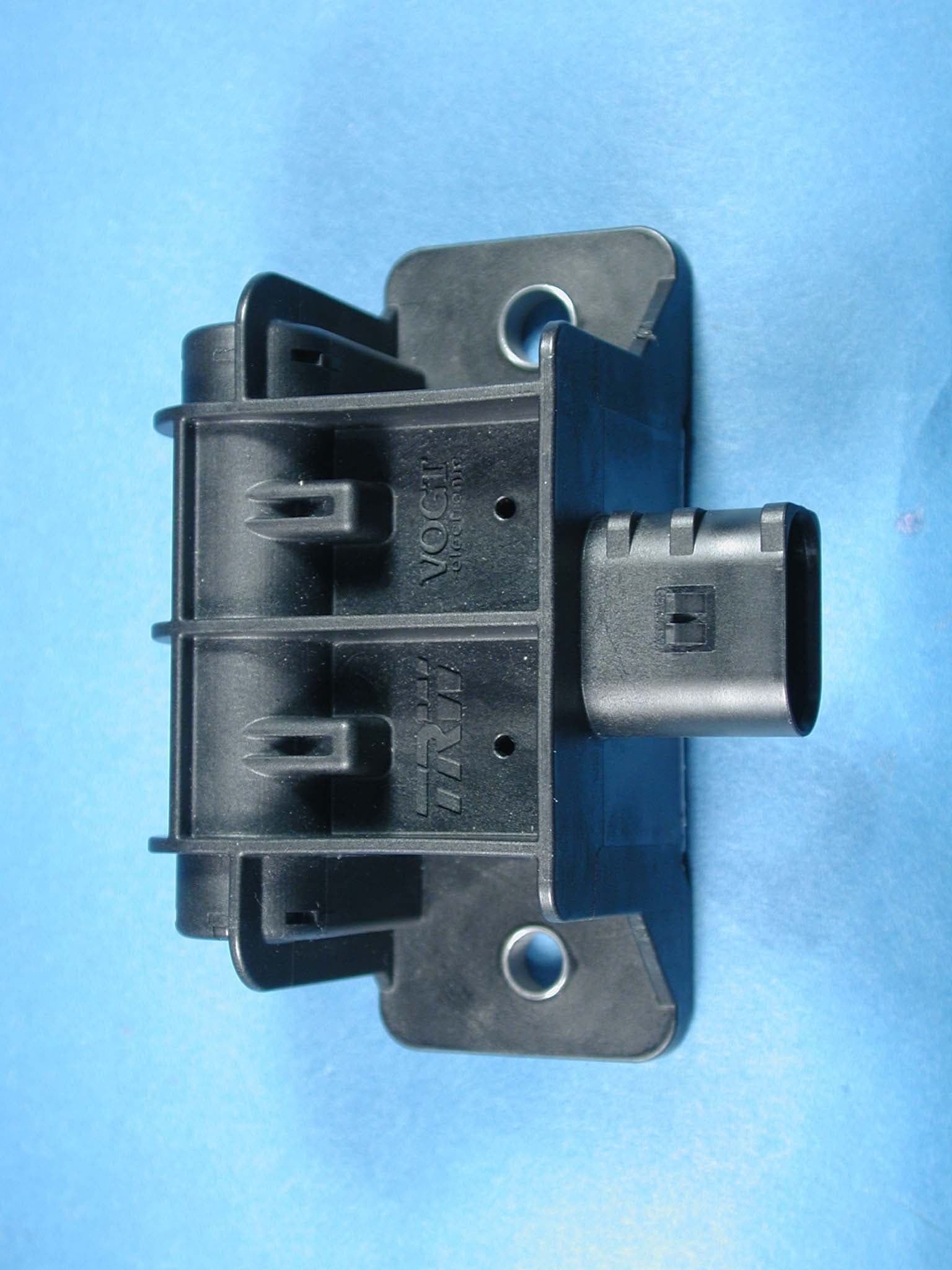
KHH29EC
Jul 05, 2004Transmitter/Initiator
Equipment Class
DCD - Part 15 Low Power Transmitter Below 1705 kHz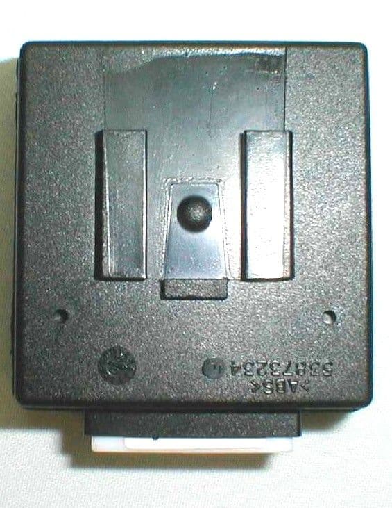
KHH37AS
Jun 19, 2000Vehicle Immobilizer System
Equipment Class
DCD - Part 15 Low Power Transmitter Below 1705 kHz
KHH20TN-1
Mar 21, 2000Remote Control Transmitter
Equipment Class
DSC - Part 15 Security/Remote Control Transmitter
KHH17TN
Sep 28, 1999DSC - Part 15 Security/Remote Control Transmitter
Equipment Class
DSC - Part 15 Security/Remote Control Transmitter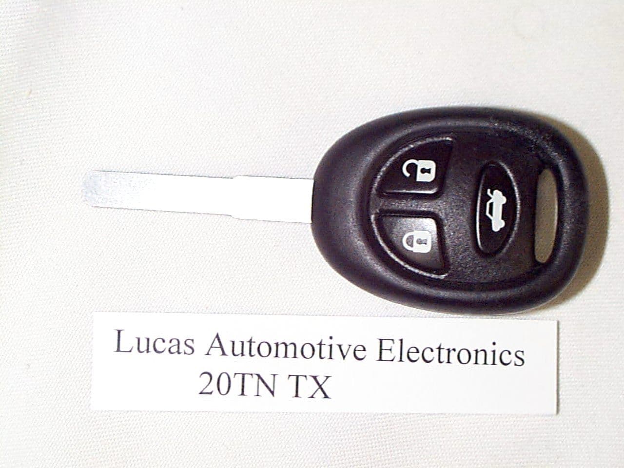
KHH20TN
Aug 23, 1999DSC - Part 15 Security/Remote Control Transmitter
Equipment Class
DSC - Part 15 Security/Remote Control Transmitter